A deep breath
I often get the impression that people don't look closely enough.
The fantastic Musical Fidelity A1, for example; often lacks an understanding of its function. The SUPRA almost follows the same principle, but only almost ... and they look so similar.
Both are controllers, in the case of the A1 even rail to rail, which is one of the reasons why it has broken down so often. The old cup warmer. I love this amp.
🙂
Attachments
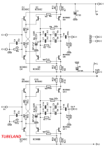
Actually, the Tubeland.de kit is nicely priced if someone want to experiment on a Supra-type topology (actually Borbely-Lender type).
Selling it as a kit I would think Tubeland has tested their kit and it should be good as is. Maybe they reduce current in output stage to avoid heat in Q3/Q6.
That being said, I would have expected R11/R12 at about 8K2 and R10 at about 2K2 or so. I'd be currious as to how this would sim
I may actually order a set and test the PCB with JFET input transistors. Way back in the mid eighties I had a Supra and remeber that I was very happy with the sound quality (although my references was very low-Fi at the time).
Elektor gave the following specifications:
SNR > 86dB
THD < 0.001%
The noise is to be reduced by a factor of 2.82 by connecting 8 transistors in parallel in ac-mode.
Correct as always Marcel, my German is very rusty, but I believe "abgescholssenem" means shorted in this contextThey probably measured with an unrealistic source impedance, for example 600 ohm instead of 600 ohm plus 500 mH.
"Abgeschlossen" would probably mean "disconnected" in contrast to "angeschlossen" (connected). Not sure if that's what they intended though.

The technical term "abgeschlossen" means in German:
with the typical source impedance against the reference potential shorted.
No short circuit or even open.
Please take a look at my sketch of the discrete (symmetrical) OP-AMP. And now a transfer to the dynamic, ac voltage world must take place. Then you can also better understand the noise issue.
Greetings,
HBt.
Attachments
"Das würde ich nicht tun!"Actually, the Tubeland.de kit is nicely priced if someone want to experiment on a Supra-type topology (actually Borbely-Lender type).
Selling it as a kit I would think Tubeland has tested their kit and it should be good as is. Maybe they reduce current in output stage to avoid heat in Q3/Q6.
That being said, I would have expected R11/R12 at about 8K2 and R10 at about 2K2 or so. I'd be currious as to how this would sim
I may actually order a set and test the PCB with JFET input transistors. Way back in the mid eighties I had a Supra and remeber that I was very happy with the sound quality (although my references was very low-Fi at the time).
I wouldn't do that.
You can see that TUBELAND must have misunderstood something.
Attachments
SUPRA
With open global loop, only to supplement the excursion /trip.
But it still revolves around possible shot noise and the base current in OREAD.
Greetings,
HBt.
Psst.
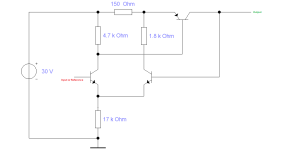
On the left of the picture you can see a positive voltage regulator and on the right a negative voltage regulator - if you like. In any case, you have two halves, which is not quite right, you could also talk about single-ended operation, but in the end you have 100% class A push-pull operation. Or also a source in 4-quadrant operation.
With open global loop, only to supplement the excursion /trip.
But it still revolves around possible shot noise and the base current in OREAD.
Greetings,
HBt.
Psst.
On the left of the picture you can see a positive voltage regulator and on the right a negative voltage regulator - if you like. In any case, you have two halves, which is not quite right, you could also talk about single-ended operation, but in the end you have 100% class A push-pull operation. Or also a source in 4-quadrant operation.
Attachments
Last edited:
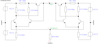
Our schematic is shown in post #2.
Since "chestnutspread" is down sick, I'll try to steer this thread a bit for now (hopefully in his best interest).
The SUPRA design excursion was for clarification purposes only.
Maybe someone has a better dimensioning and transistor suggestion, or a different topology with a maximum of 5 active transistors, unipolar or bipolar. The better one might be the EQ of the AR A-03, but that would be a clone.
Anything constructive is very welcome,
HBt.
Until you replace the bipolar transistors in the input stage with JFET ones (I recommend JFE2140), the large shot noise of the base current flowing through the almost 1H inductance (or or 10th of kOhms impedance @ mid HF 5 kHz) of the MM cartridge will not allow you to minimize the overall noise regardless of the number of paralleled bipolars. MarcelvdG have already told you about this several times in great detail.Our schematic is shown in post #2.
Last edited:
my German is very rusty, but I believe "abgescholssenem" means shorted in this context
View attachment 1246994
Thanks for digging this up. Unfortunately, abgeschlossenem means terminated, so you still don't know anything when they don't tell you what they terminated it with...
Thanks Nick, thanks Marcel, "several times" - "in great detail" ...i know and understand perfectly.
;-)
My question is and remains the following: why does the universally valid postulate not seem to have been taken into account in the examples I have given? Why does the SUPRA work without disturbing shot noise???
But we don't have to argue and want to be right, that doesn't help.
HBt.
;-)
My question is and remains the following: why does the universally valid postulate not seem to have been taken into account in the examples I have given? Why does the SUPRA work without disturbing shot noise???
But we don't have to argue and want to be right, that doesn't help.
HBt.
Last edited:
Thanks for jumping in here - I need a couple more days to be back on track.Our schematic is shown in post #2.
Since "chestnutspread" is down sick, I'll try to steer this thread a bit for now (hopefully in his best interest).
The SUPRA design excursion was for clarification purposes only.
Maybe someone has a better dimensioning and transistor suggestion, or a different topology with a maximum of 5 active transistors, unipolar or bipolar. The better one might be the EQ of the AR A-03, but that would be a clone.
Anything constructive is very welcome,
HBt.
The entire base for this phono pre was basically your idea with just a couple of mentions from my side.
From what I have seen I assume you are more than suited to take over.
When I'm alive again I will DM you and we can have a little chat where we are and what's missing.
I appreciate the effort already done here and guys be nice - it's the first time publishing and working in community here in this forum.
Hopefully nothings misunderstood due to lost in translation but I see some real nice info!
Today at whats cooking on your desk - inhalation with salt water 🙂
Thanks Nick, thanks Marcel, "several times" - "in great detail" ...i know and understand perfectly.
;-)
My question is and remains the following: why does the universally valid postulate not seem to have been taken into account in the examples I have given? Why does the SUPRA work without disturbing shot noise???
But we don't have to argue and want to be right, that doesn't help.
HBt.
Regarding your second question: it's no big mystery, in fact I hinted at it in post #17. Noise optima are rather broad and there is simply quite a difference between the noise level that the average user would find disturbing and the noise level of a carefully optimized moving-magnet amplifier. As a result, you have to be very far from the optimum before it gets disturbing to most users.
Like I wrote, when the 47 kΩ termination resistance is made with just a resistor shunting the input, it injects 0.5869 pA/√Hz of noise current into the node that connects the cartridge, the resistor and the input of the rest of the amplifier. I have shown in my 2003 article that the thermal noise of the cartridge is of the same order of magnitude as that of a 47 kΩ termination resistor when you take into account things like iron losses. Hence, when you add an NPN stage/bunch of NPN stages with 1.075 µA total base current and a PNP stage/bunch of PNP stages with 1.075 µA total base current, the noise with no record playing gets 3 dB worse than when you only had the cartridge and resistor as noise sources and 6 dB worse than when the cartridge were the only noise source.
That's simply not bad enough to annoy most users, particularly when they only care about the noise when there is a record playing. Record noise is usually far stronger than cartridge thermal noise and phono amplifier noise. Nick is an exception to this rule: as the current noise gets converted into a voltage across the inductive impedance of the cartridge, it sounds sharper than normal record surface noise. He finds that quite annoying.
Still, I have seen a thread on this forum from someone, not Nick, who had built a phono preamplifier with an LT1028 and found the hiss annoying. He wasn't aware of the issue of noise current, so it rather surprised him that his expensive ultralow noise op-amp produced annoying hiss. Mostly due to their base current compensation circuit, the LT1028/LT1128/LT1115 family of op-amps have an equivalent input noise current of about 3.4 pA/√Hz when measured under realistic circumstances. (The LT1028 moving-magnet version of the Elektor Supra 2.0 is even worse, it uses four LT1028s to produce as much as 6.8 pA/√Hz.)
Regarding your first question: moving-magnet phono amplifiers are more often than not measured with a 600 Ω source impedance. Each pA/√Hz produces only 0.6 nV/√Hz across 600 Ω, but 12 nV/√Hz across the 12 kΩ effective RIAA- and A-weighted average cartridge impedance that I estimated in my 2003 article for a 500 mH cartridge. It is therefore very easy to largely overlook the effect of noise current. In fact, even Douglas Self did it wrong until I pointed it out to him in the mid 1990's - it was kind of funny, because he was already a famous writer back then and I was completely unknown and in my mid 20's.
Apparently Stereophile also uses 600 Ω rather than 600 Ω + 500 mH or so. That means that for an amplifier with a bipolar input stage, the designers can choose between as low a noise level as possible with a cartridge connected to the input, or as good numbers as possible during a Stereophile test - you can't have them both...
Besides, one of the circuits you showed looks like an amplifier for moving coil cartridges that also supports moving magnet. Because of the much lower impedance and much lower output voltages of moving coil cartridges, equivalent input noise current is not much of an issue, but equivalent input noise voltage is much more critical than for moving magnet. If you want to support both moving coil and moving magnet, you can either choose a compromise collector current, or make it switchable, or optimize for one of the two and accept suboptimal performance for the other type. Or use really high transconductance JFETs - not having any base current and practically no gate current, they produce almost no equivalent input noise current.
Last edited:
Thank you very much for your last contribution Marcel.
This is exactly how I imagine a contribution that is understandable for the general public. To let the cat out of the bag: sentences like this " MarcelvdG have already told you about this several times in great detail." I react with a slight huff and can become very unpleasant as a result. Very clearly and unmistakably: I am also a professional.
So thank you once again Marcel for clarifying your positions, which you are right about.
At the moment, I'm really fascinated by semiconductor physics and the question of the causes of shot noise. My thoughts are entirely in the field of the PN transition.
All the best,
HBt.
We can talk about noise and network analysis (including correct modeling) elsewhere, but we don't necessarily have to, because I'm convinced that we both know our business.
All callers may also assume that I have mastered the underlying field.
So if a discussant wants to bring up closing impedances or the MM system as such, he must be prepared for the fact that his counterpart is watertight.
I hope now, we can help "Chestnutspread" in his search for an exciting and simple equalizer.
Critical questions are very welcome, they serve to clarify the facts. Concrete dimensioning suggestions based on the input circuit as well.
So let's move forward ...
Best regards,
HBt.
"Nachtrag":
By the way (this is just for clarification),
I recognize any intention of manipulation in the bud and also whether a heckler has informed himself comprehensively or not.
Now - back to the fun-project.
Last edited:
In this instance it means "Input connector shorted" or "signal to noise with input shorted" 😉"Abgeschlossen" would probably mean "disconnected" in contrast to "angeschlossen" (connected). Not sure if that's what they intended though.
^
I fear that too "Boydk". But i hope it isn't. "Elektor schrieb nicht "mit kurzgeschlossenem Eingang" " - that means the term shorted.
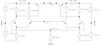
Here is an adapted dimensioning example of the first stage of the possible discrete OP amp ... The question of the most suitable transistors at this point is still open.
Shot-Noise should be no longer an issue.

I fear that too "Boydk". But i hope it isn't. "Elektor schrieb nicht "mit kurzgeschlossenem Eingang" " - that means the term shorted.
Here is an adapted dimensioning example of the first stage of the possible discrete OP amp ... The question of the most suitable transistors at this point is still open.
Shot-Noise should be no longer an issue.
Last edited:
The first evolutionary step
frequency compensation is still missing ... the stability criteria! My approach is still strictly intuitive, that is the intention.

frequency compensation is still missing ... the stability criteria! My approach is still strictly intuitive, that is the intention.
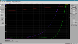
Measurements on an AT420E/OCC MM system (with HM8018 LCR bridge, FLUKE 73 Multimeter, DATS V3)
left: "100Hz to 25kHz"
Rdc = 385 Ohm
Ls = 515.4mH to 269.6mH
Rs = 406.8 Ohm to 21.83 kOhm
Ls_1k = 481.8mH & Rs_1k = 734.2 Ohm; Lp_1k = 510.7mH & Rp_1k = 13.22 kOhm
right: "100Hz to 25kHz"
Rdc = 385 Ohm
Ls = 520.5mH to 276.2mH
Rs = 393.7 Ohm to 21.47 kOhm
Ls_1k = 483.9mH & Rs_1k = 751.1 Ohm; Lp_1k = 513.8mH & Rp_1k = 13.01 kOhm
The manufacturer's specifications are as follows:
|Z1k| = 3k1; L1k = 500mH; u_max = 4.5mVrms at 5 cm/sec and 1kHz sine wave!
This is the only MM I currently have to hand. The moving magnet was not clamped, but moved freely during excitation and measurement.
As we can see, the series equivalent circuit is dependent on frequency as follows: Rseries increases and Lseries decreases.
The parallel equivalent circuit results in a slightly different function, let's think of a classic resonant circuit ... ultimately, as we all know, the result is (at the end) a higher-order low-pass filter with a quality factor (hope) not greater than 1, which is why we have to terminate the signal generator correctly.
Without a capacitive termination, the highs could be lost, right?
Cp||47k
Z(25kHz) = 21,645kOhm +j (42,867kOhm) ---> |48,022kOhm| The manufacturer's specification of a 47k termination is correct.
Now we just have to play with Cp until we achieve a Q between 0.707 and 1, done
Bye,
HBt.
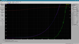
Attachments
Last edited:
Supplement to the data of the AT420E:
fl = 15 Hz
fh = 25 kHz
That fits!
What should our dummy (load) for a simulation look like now?
fl = 15 Hz
fh = 25 kHz
That fits!
What should our dummy (load) for a simulation look like now?
With hfe=500 and UT=26mV is IC=174,2uA the optimum, rbb=0 Ohm, 23kOhm > source >515 Ohm, b=9k9Hz.
With rbb=10 Ohm it's 188,5uA, source 3k3.
Approx 200uA is totaly fine. The calculation is an easy task, lowest shotnoise now - in practice.
Sometimes textbooks are friends.
;-)
With rbb=10 Ohm it's 188,5uA, source 3k3.
Approx 200uA is totaly fine. The calculation is an easy task, lowest shotnoise now - in practice.
Sometimes textbooks are friends.
;-)
- Home
- Source & Line
- Analogue Source
- Oread - a DIY MM phono approach