Just now
I reread what Douglas Self writes about this in his popular green book "small signal design". And that really spoils the fun, mean of him - I say it again and again: take a single NE5534.
😉
But that's exactly what we don't want to do here, and I want current - there must be a way ... head scratching!
Maybe we should modulate the MM system for a simulation (at least now I know why I love MCs so mutch).
It remains exciting,
I shout "Chestnutspread", where are you?
HBt.
National Semiconductor manuals through the mid 1970s and early 1980s contained a lot of variations on the 5534 input stage, replacing it with a variety of alternatives including cascoded JFETs and LM194s (hope I remember that right - the precision matched pair monolythics with multiple paralleled n-channel BJTs). Also some info about forcing the output stages into more Class A with a CCS from negative supply.
Have given mine away, but might still be available somewhere online. The basic idea for inputs was to tie IC input pins to V- and add a new diff input pair with its own CCS from V- to pins (uniquely) exposed on the the 5534, with resistors soaking up extra current to V+. IIRC, voltage drop from exposed pins from V+ is 1.37VDC, but you'll really need to check that.
All good fortune,
Chris

The discrete OP of the SUPRA-EQ looks slightly different from the previous working proposal of the OREAD-EQ. The original SUPRA had a kind of sweet spot at +/-17.3V to +/-18.8V rails.
Elektor gave the following specifications:
SNR > 86dB
THD < 0.001%
The noise is to be reduced by a factor of 2.82 by connecting 8 transistors in parallel in ac-mode.
Elektor gave the following specifications:
SNR > 86dB
THD < 0.001%
The noise is to be reduced by a factor of 2.82 by connecting 8 transistors in parallel in ac-mode.
Attachments
Last edited:
They probably measured with an unrealistic source impedance, for example 600 ohm instead of 600 ohm plus 500 mH.
Unfortunately, Elektor (1982) did not provide any further details on their measurement method and conditions.
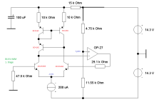
Burkhard Vogel's book "the sound of silence"
is another treasure trove, I am attaching a picture of his BUVU-MM input stage (page 191) - for further confusion or information.
Burkhard Vogel's book "the sound of silence"
is another treasure trove, I am attaching a picture of his BUVU-MM input stage (page 191) - for further confusion or information.
Attachments
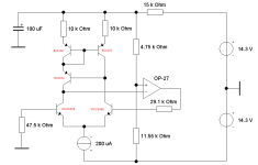
Roughly estimated: apparently the (total) base current of the NPN input transistor(s) is just a bit more than 1.075 μA, the same holds for the base current of the PNP side and the resistor is a bit more than 47 kΩ. The total noise current will be about √3 times the noise current of 47 kΩ, so about 1 pA/√Hz.
Heyho everyone. I'm happy to see that there is some interest - after my last life sign I ended in bed with a bad cold/flu and since then I'm in progress of manly dying.
As soon as I'm able to read more than one sentence I try to catch up and see what happened to this little project. But again I'm sorry for the abstinence - fingers crossed my manly dying ends at this weekend!
As soon as I'm able to read more than one sentence I try to catch up and see what happened to this little project. But again I'm sorry for the abstinence - fingers crossed my manly dying ends at this weekend!

If I'm wrong, I apologize as a precaution (it's due to chronic sleep deprivation, you can't sleep in Germany with the light and noise pollution allways around).
R=47kOhm
b=20kHz
T=20°C
uR=3.899µV
"The 1*10^-12 A/sqrt(Hz)" additionally lead to non-correlated 6.647µV - are we actually allowed to say RMS when it comes to statistical normal distributions?
Two noise sources, and we are not allowed to subtract or add arithmetically. The magnitude ratio 6.647/3.899 = 1.7048 -> approx. sqrt(3) or 4.6dB - exactly as you estimated it' Marcel.
But an original SUPRA is not noisy, at least I don't remember that - but I could do a measurement at home at the weekend and terminate the input with an ancient MM. However, I fear trouble with my wife for turning our home into a laboratory so close to Christmas.
Greetings,
HBt.
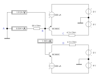
My point of view:
The thing is a bridge, ideal and static - considered point B is zero. The defect current of the PNP controls both transistors (Douglas Self will give a different model view) ... But what happens here dynamically, we cannot look into the line or the path resistance.
The random shot noise must be processed and considered statistically. Well, point B is flowing and we lash it with R=56kOhm to GND.
What happens now if we add the two new sources C and D, their noise does not correlate.
This question's concerns me with regard to the propagated SNR > 86dB and the fact that the circuit works fine - no disturbing noise, only split the tailcurrent ...
HBt.
Addendum:
Of course we can now determine the optimal collector current - but for the case at hand?
Attachments
Last edited:
The PreAmp-1987 from Elektor operates with a total current of 5mA. 824µA dc per NPN. The technical data are excellent and there have never been any complaints or objections. Elektor even states a fabulous SNR of >92dB for the high level MM. The normal type is >86dB.
What have the technicians and engineers
did wrong or did not understand correctly (date 1987) - I ask myself?!
Is it due to the MAT-02 miracle or the low output impedance of the differential amplifier?
Dear Marcel,
perhaps you can help me to untie the knot.
😉
Regards,
HBt.
What have the technicians and engineers
did wrong or did not understand correctly (date 1987) - I ask myself?!
Is it due to the MAT-02 miracle or the low output impedance of the differential amplifier?
Dear Marcel,
perhaps you can help me to untie the knot.
😉
Regards,
HBt.
Attachments
By the way,
the equalization is based on the same principle as the current Pearl3 from PassLabs Wayne Colburn - nothing new, but perfect.
The internal noise canceling of the OP27 also works, because they see almost identical impedances at their inputs - that's nothing new either.
IC2 could be a little bit better on this point.
Last edited:
Back to the current OREAD OP-Amp in the monster version with 19 transistors, where it could still turn out to be a problem with the possible shot noise.
Trevor Marshall points out in the 1977 (round about) that we should distribute the currents unevenly. And that's a good idea, we don't have to do any awkward selecting (but only form approximately equal pairs) and vary the common emitter resistance slightly in each case ... so now there is really no correlation at all and everything is random, but under no circumstances should we allow unpleasant shot noise.
I look ahead.
HBt.
Psst
Maybe Douglas S., Bob C. or John C. will turn up here in this hobby thread. That would be a great pleasure and honor.
Dear Chris,National Semiconductor manuals through the mid 1970s and early 1980s contained a lot of variations on the 5534 input stage, replacing it with a variety of alternatives including cascoded JFETs and LM194s (hope I remember that right - the precision matched pair monolythics with multiple paralleled n-channel BJTs). Also some info about forcing the output stages into more Class A with a CCS from negative supply.
Have given mine away, but might still be available somewhere online. The basic idea for inputs was to tie IC input pins to V- and add a new diff input pair with its own CCS from V- to pins (uniquely) exposed on the the 5534, with resistors soaking up extra current to V+. IIRC, voltage drop from exposed pins from V+ is 1.37VDC, but you'll really need to check that.
All good fortune,
Chris
thank you very much for your comment. I know very well that all these tomes were still on the shelf in our office /lab at the beginning of the 1990s. That's all lost now. At the end /late of the 1990s, we all thought that the CD-ROM or DVD would replace a real paper archive. Today I no longer have a single copy.
😢
I search - but I can't find them and I can still remember them clearly.
Those were good times and I was young.
Best regards,
HBt.
Dear "Chestnutspread"
We could copy the legendary EQ of the AR A03. It works with five transistors and three diodes and operating voltages of +/-25Vdc. It has no temporary clipping problems and sounds like a dream, completely light, as if it didn't even exist. Its input pair shares just under 1mAdc tailcurrent, i.e. 500µA per 2SC2602G ... quiescent current of the output stage at least 8mAdc.
And the crazy thing is, I didn't hear it crackle or fire. However, I did not measure anything. Why should I, it obviously works perfectly. The pseudo current mirror is formed by a 2SA608k ... that could be OREAD, but unfortunately that would be a write-off.
Bye,
HBt.
There is no way getting around a test setup.
Last edited:
Hi, the input stage of this amp is more or less direct from the "SSM2210 datasheet for the "500pV/rtHz" amplifier. The input stage is probably best suited for HOMC pickups since their induction is much lower compared to regular MM pickups. The Ortofon red/blue/black series pickups are on other end of the scale...... The PreAmp-1987 from Elektor operates with a total current of 5mA. 824µA dc per NPN.....
..... did wrong or did not understand correctly (date 1987) - I ask myself?....
As for doing wrong, the current noise mechanism were well known, and if I remember correctly was more a focus for tape-head amplifiers in cassette decks.
Focus for voltage noise is more appropriate for MC and HOMC pickups, and voltage noise is easier to measure and understand for most. We did'nt have the internet to educate us the same way DIY-audio do today.
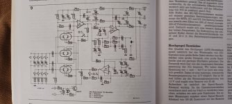
The PreAmp from 1987 you refer to had about 5mA total current in input stage, The supra with its16 transistor input had about 1,4 mA and the Tubeland DIY kit has 0,7mA (basically a 24 volt ersion of Supra with single input stage) https://www.tubeland.de/product_info.php?products_id=35
Attached also all 3 schematics for easy comparison. It seams to me that "tubeland" forgotten to scale resistors R7,R8, R11/R9,R10,R12 and hence Q3/Q6 is running current starved.
Regarding the original Supra. I'm curios if someone has an opinion using a diode instead of 1K8 resistor to achieve 0,6 volt drop instead of R12/R14
The ensemble in the SUPRA is not a classic current mirror!
Dear LJT,
we seem to be playing in the same league 🙂.
Let's leave aside all the copycats, e.g. "Röhrenland", which I also found yesterday.
You're absolutely right about the 1k8 resistor. In my eyes and measurements plus simulations, it is unfavorably dimensioned.
Greetings to Norway,
HBt.
Dear LJT,
we seem to be playing in the same league 🙂.
Let's leave aside all the copycats, e.g. "Röhrenland", which I also found yesterday.
You're absolutely right about the 1k8 resistor. In my eyes and measurements plus simulations, it is unfavorably dimensioned.
Greetings to Norway,
HBt.
- Home
- Source & Line
- Analogue Source
- Oread - a DIY MM phono approach