Forget about the "AI" - the chip is included but this feature never made it into production. They promoted a bit too quickly before they have seen that it's not as easy as initially thought - I cannot remember the source of this info but in the end I don't listen with a subsonic. I just use a small two-way system that is not able to go that low and somehow the active subsonic makes the sound a bit muddy.The manufacturer's specifications for your Ifi ZEN Phono promise absolute high-end qualities and even a subsonic filter with its own artificial intelligence.
SNR |80dB| unweighted, based on an output voltage of 2Vrms -> 5.66Vpp (balance). And all this with a Vu of 36dB +/- 1dB for MM systems. Then we can carry out a plausibility check, 63.1 * 5mVrms = 315.5mV.
20*log(1V / 0.3155V) = 10dB, unfortunately we have to subtract these 10dB from the 80dB. What remains is an unweighted SNR_mm of just under 70dB.
The built-in DC-DC converter and the microcontroller will also contribute to the music enjoyment.
That's how you praise it.
😢
The Pre is nothing fancy and is more on the clinical side. I compared it to a NAD PP2 and even tried the musical fidelity VNYL. The PP2 got this nice warm sound, clarity without being to crispy and well the low-end is also more on the warm side. It plays very well and is more preferable than the Zen, some records cannot be listened to - too clean is not always good. 😉
Just needed something doing it's job after having a failed phono in my amp.
When the holiday madness is over we can do some tests and also have a look inside the Zen if you are interested.
Your math seems logically but these numbers are only telling half the truth.
I would be totally in just to see how well something complex with basic transistors is playing. The solution needn't to be reduced to the least amount of parts - only available parts, that's the only mayor point that I'm focussing.Well, that was Nick Sukhov's point about avoiding the potentially very unpleasant shot noise - and of course because his own design includes a jFet differential amplifier as the first stage. I would like to refrain from this kind of solution strategy for the time being. For various reasons 😉.
The more we fidget around, the more I tend to try the overkill variant with nineteen BJTs - if only to see real measured values, a testboard as a layout exists. With unevenly distributed quiescent currents. Nobody else dares.
Greetings,
HBt.
"Tipp:"
https://www.tacet.de/main/seite1.php?language=de&filename=production.php&bestnr=02101
You mentioned owning variants of the Pearl means a competitor with JFETs at the input stage.
I do have this retail Zen thingy from IFI - let's simply do it and have some fun 🙂
Have fun with backward engineering and pixels 😀https://ifi-audio.com/products/zen-phono/
Does anyone have a circuit diagram of the ifi ZEN at hand?
Sorry,
but the advertising is so cool - I'm laughing under the table, advertising is the "A" and "O".
I would like to test the equalizer (myself).
At first I didn't understand why you wanted to build an EQ yourself and develop it yourself - now I do.
🙂
Sorry for this type of reaction but honestly it's a tiny SMD box that runs on 5V - we are following a total different approach with a hopefully different sound signature. I don't want to have a self-made copy of what I already have and can buy on the whim on Amazon
Attachments

I asked for a circuit diagram of the IFi-ZEN-Phono because you can predict pretty well from the circuit diagram - what's going on there.
The NAD PP2 (in my version) that you (and I) praised is nothing more than a standard solution, i.e. this EQ shows you what is possible with it. The MC-Pre is completely symmetrical and complementary (discrete 4 BJTs, current feedback mode), the power supply is a simple parallel regulator +/- 9V (LM317 as current source plus Z-diodes as parallel elements). Network no. 4 is used in RIAA. The NE5534 or NE5532 is used as the OP. The inevitably resulting fourth time constant is equalized by means of passive TP1. And this is exactly how it is done. The next larger EQ from Cambride Audio wants to be a little more sophisticated, but it beats them both from Musical Fidelity - in this price range. Based on the MF (and also the PP2 and the CA), I designed my own circuit, the EXakt-MK2. Especially for MC systems. Maybe I'll post the project here in the forum at some point. You can see a picture of the final prototype in the Haudegen thread.
If there are any concerns, Haudegen can deliver almost daily. Yesterday he stumbled across the DUAL TVV47, see for yourself in the corresponding thread. There shouldn't be any problems with the potential shot noise of the first stage, but all sorts of other phenomena can also make a nonsense of this neat idea. C1=1.5nF FKP and C2=1nF in series 1nF=500pf FKP.
There is no getting around a laboratory setup!
Regards,
HBt.
Last edited:
see here https://www.patreon.com/posts/86997687Nick Sukov's EQ is a three-stage one, is that correct?
Dear Nick Sukhov,
I am not registered with PATREON and do not really want to register there. I assume that "ChestNutSpread" has no objection if you share the circuit diagram in the clear image here (in this thread).
Thank you very much.
Best regards,
HBt.
I am not registered with PATREON and do not really want to register there. I assume that "ChestNutSpread" has no objection if you share the circuit diagram in the clear image here (in this thread).
Thank you very much.
Best regards,
HBt.
Is this your circuit, we must have in mind?

"SPlan und Sprint Layout aus Norddeutschland".
nice
😉
"SPlan und Sprint Layout aus Norddeutschland".
nice
😉

Dear Nick,
that's a nice cascading of two complex voltage dividers. How did you come up with this idea, is it RIAA, IEC compliant? That looks a bit like it was put together 😕. What were your motives for designing the entire circuit in this way?
Regards,
HBt.
that's a nice cascading of two complex voltage dividers. How did you come up with this idea, is it RIAA, IEC compliant? That looks a bit like it was put together 😕. What were your motives for designing the entire circuit in this way?
Regards,
HBt.
Attachments
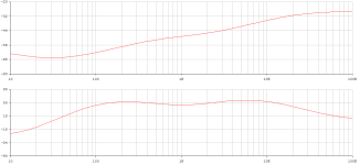
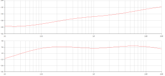
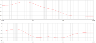
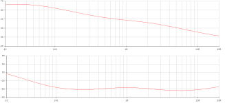
The expected deviations ...
(approx.)
100Hz +0.4dB
200Hz +0.36dB
400Hz +0.26dB
800Hz +0.45dB
compared to the actual RIAA curve. Above f=1kHz it gets much better, but then comes Nick's built-in stop!
Provided, the amplifier in nfb-mode is ideal, i.e. ra = 0Ohm, re = infinity, G=infinity. But the output resistance of Nick's topology, as well as that of the OREAD, is huge in the open loop. Only the negative feedback reduces the ra, depending on the frequency, among other things.
The use of an op-amp after the jFet differential amplifier would be a much better alternative.
Attachments
Cant you see my preamp has a DC servo? Dont you know https://www.diyaudio.com/community/...o-precorrecting-riaa-correction-poles.406227/ ? It seems you need Dunning-Kruger help 🤔
The Dunnig-Krueger effect is as old as forum culture itself. Pretty hackneyed.
The most sensible posting behavior is:
read carefully, ask questions and answer questions, share further information on facts with others.
I can only say that I don't like your beautiful circuit Nick and I think you could have solved various problems better. But that's not really interesting, because I'm only interested in your motives. I am interested in the details. Either you explain your way or you don't.
As you don't know me personally, and that will remain the case, we will no longer insult each other or accuse each other of ignorance.
Have you understood these points and can you accept them, even if it might be very difficult for you?
I'm not interested in you as a person, I'm only interested in your assertions and circuit suggestions.
Bye,
HBt.
It would be nice to have both of you more on the technical than offensive side.
I appreciate the explanation and especially the effort you put in your design. To be honest I still don't get the DC servo part. I read the document from Marcel and it makes kind of sense but I don't get the reason of going that route. Probably I need to try it out once to get the right idea of this principle.
Everyone reading have some nice holidays with the most important close by. Before the madness begins I have a nice glass of whiskey and enjoy the silence and calm my agnostic soul 😉

Circuit diagram from post #87 has been deleted as it is apparently under copyright.
(You will have to post a valid link to wherever it is hosted)
But that is very strange Mooly,
since when can you patent a simple equalizer preamplifier?
Above all, I had taken the circuit diagram from the forum here and pasted it into this thread, there was no copyright or patent location marked.
Very strange - nevertheless, many thanks for the information in this regard,
HBt.
since when can you patent a simple equalizer preamplifier?
Above all, I had taken the circuit diagram from the forum here and pasted it into this thread, there was no copyright or patent location marked.
Very strange - nevertheless, many thanks for the information in this regard,
HBt.
I am always on the technical, physical side - but also on the human, empathetic side.It would be nice to have both of you more on the technical than offensive side.
(...) 😉
Regarding the (Nikolai Yevgenjevich Sukhov) EQ circuit, I could ask Haudegen to analyze the deleted circuit in his thread and explain it in detail, he has a photographic memory.
I'm already looking forward to meeting you in real life next year.
Happy Christmas,
HBt.
PS
OREAD2024
🙂
The item was reported to us by the author as being under copyright and given that claims and counterclaims of copyright are a legal minefield you would have to direct your concerns to the author. It is in our interest not to get embroiled in such matters.
Thanks for your understanding on this.
https://www.diyaudio.com/community/...-phonopreamps-x-altra-lp797-vs-cy-xxi.402205/
here is the LINK "Mooly",
Nick Sukhov has published the plan here in the forum, by himself.
Many thanks Mooly,
I really didn't do anything wrong. The problem obviously lies with the creator of the circuit and not with me - I really want to behave in an exemplary manner and hope for your (admin, mods ...) support in this regard.
I will be even more careful and cautious in future.
Best wishes and merry christmas to you,
HBt.
Last edited:
You have done nothing wrong 🙂 these things happen all the time.
If Nick Sukhov himself posted that diagram here (and he obviously has done) then he has agreed (in the site rules that everyone agrees to in being a member here) to allow that work to be used freely by not only himself but by others including diyAudio. As such I am going to add the image from that diyAudio link back to your original post.
From the rules:
User Contribution to our website.
By sharing any contribution (including any text, photographs, graphics, video or audio) with diyAudio you agree to grant to diyAudio, free of charge, permission to use the material in any way we want (including modifying and adapting it for operational and editorial reasons).Copyright of your contribution will remain with you and this permission is not exclusive and you can continue to use the material in any way including allowing others to use it.
In order that diyAudio can use your contribution, you confirm that your contribution is your own original work, is not defamatory and does not infringe any Australian laws, that you have the right to give diyAudio permission to use your contribution.
diyAudio does not undertake to monitor the submission of any user generated content, or the publication of this content on our website.
- Home
- Source & Line
- Analogue Source
- Oread - a DIY MM phono approach