
OREAD works 🙂
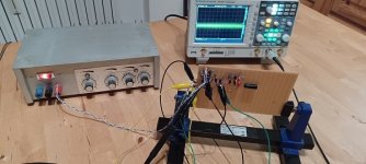
measured, overlapped, listened to with headphones (turned up to maximum!)
I couldn't wait!
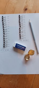
To do a test setup with the good old BC560C and BC550C. I quickly determined hfe and started soldering. Please bear with me regarding the flying setup.
And the biggest surprise is:
no disturbing or even audible shot noise. Of course it is there, but not really significant. Roughly speaking, the unweighted SNR is already >76dB.
A proper layout and an RF-tight shielding housing and so on, and OREAD will be a success. I am already very satisfied with the first step.
HBt.
measured, overlapped, listened to with headphones (turned up to maximum!)
I couldn't wait!
To do a test setup with the good old BC560C and BC550C. I quickly determined hfe and started soldering. Please bear with me regarding the flying setup.
And the biggest surprise is:
no disturbing or even audible shot noise. Of course it is there, but not really significant. Roughly speaking, the unweighted SNR is already >76dB.
A proper layout and an RF-tight shielding housing and so on, and OREAD will be a success. I am already very satisfied with the first step.
HBt.
Attachments

There are SMT equivalents to most of these - alas I've not yet found a good resource for mapping through-hole to SMT versions. For instance
KSA992 becomes FJV992
ZTX951 becomes ZXTP2012
BC109C becomes BC849C
Dear Mark,
Please feel cordially invited to help make the tiny OREAD a success. Suggestions and cooperation are welcome.
Regards,
HBt.
Last edited:
The purpose of this and the Haudegen thread is to encourage you to "simply reach boldly into the component box" and give free rein to your own creativity - motivation.
The OREAD project shows how easy it is - to do this, even the (otherwise usual) symmetrical supply voltage can be dispensed without losses - coupling capacitors should be used anyway. Finally, our throw should also be safe to operate and not go up in smoke if it is accidentally reconnected.
The simple, but not stupid, discrete op-amp has now been successfully tested. The promptly expressed concern that the collector DC current of 500µA was far too high could not be confirmed. This was not an exclusion criterion - the five transistor topology works perfectly. Personally, I am not surprised by this. This first attempt has now opened the door to the overkill variant.
Here is just another commercially successful example from the industry.
The manufacturer specifies:
For general information only!
The manufacturer specifies:
- +/- 0.8dB deviation from the standard curve in the range from 30Hz to 15kHz
- an unweighted SNR of 79dB, rated at 86dB at full scale of the entire amplifier and nominal load.
- unweighted at room volume, an SNR of 75dB to 78dB remains
- input sensitivity 2,5mVrms
For general information only!
Attachments
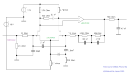
A final illustrative example concludes this excursion into the world of jFet's
The specifications are identical to the previous example, but here the clipping resistance / strengh is also indirectly specified as >34dB (f=1kHz).
A jFet input pair has been common practice for (four) decades ...
The integration of the coupling capacitors in the negative feedback loop can be seen very clearly (here as an example) and much more.
More circuit examples will not follow from my side on the subject of jFet. OREAD is fully BJT's.
Attachments
Hi...
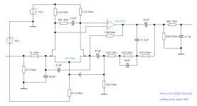
I found this interesting , so I put the circuit from post #124 into LTspice to play around with it.
It simulates corresponding to the above shown voltage measurements.
With the used reverse RIAA input it simulates a bit more linear with C8=58n, stays within ~0.1db

I found this interesting , so I put the circuit from post #124 into LTspice to play around with it.
It simulates corresponding to the above shown voltage measurements.
With the used reverse RIAA input it simulates a bit more linear with C8=58n, stays within ~0.1db
Attachments
Last edited:
Cool
C8 is now 58nF 🙂,
cause R14 = 4k695 and R13 = 55k305 with C9 = 15,974nF and C8 = 57,555nF (as calculated) ! Would you like to generate a THD plot "catd"?
Nice that you are with us on board,
HBt.
C8 is now 58nF 🙂,
cause R14 = 4k695 and R13 = 55k305 with C9 = 15,974nF and C8 = 57,555nF (as calculated) ! Would you like to generate a THD plot "catd"?
Nice that you are with us on board,
HBt.
Last edited:


This means that we can state or expect a THD of <0.01% at full scale and under loadconditions with a clear conscience.
Not bad.
Two 9V batteries can be used as power supplies if you would like to try this out.
Not bad.
Two 9V batteries can be used as power supplies if you would like to try this out.
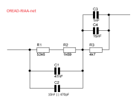
4k7Ohm * 16nF = 75,2µsec; 55k29Ohm * 57n47F = 3177,5µsec; 4k332Ohm * 73n47F = 318,3µsec
Here is a fairly accurate RIAA approximation with available standard components (in Germany, REICHELT).
1% metal film resistors and 2.5% FKP, Styroflex, MKP, MKS film capacitors. BC550C & BC560C are also available.
All that is missing now' is a sensible layout, a circuit board and housing.
Here is a fairly accurate RIAA approximation with available standard components (in Germany, REICHELT).
1% metal film resistors and 2.5% FKP, Styroflex, MKP, MKS film capacitors. BC550C & BC560C are also available.
All that is missing now' is a sensible layout, a circuit board and housing.
Attachments
Last edited:
Below are LTspice-Files with symmetrical power supply.
I simulated with +9V/-9V, (directly, without cap multifier) this shows same results as with single supply 18V.
Simulation with +15V/-15V shows a bit better performance, e.g. lower THD, which appears in the fourth place after the decimal point.
I think this doesn`t matter in real live.
I would prefer a kind of universal board, one per channel, which supports the multitrans version as well as single- and symmetrical supply.
I simulated with +9V/-9V, (directly, without cap multifier) this shows same results as with single supply 18V.
Simulation with +15V/-15V shows a bit better performance, e.g. lower THD, which appears in the fourth place after the decimal point.
I think this doesn`t matter in real live.
Will you do it yourself or should anyone else? Wouldn't make sense to later have more different layouts then needed.All that is missing now' is a sensible layout, a circuit board
I would prefer a kind of universal board, one per channel, which supports the multitrans version as well as single- and symmetrical supply.
Attachments
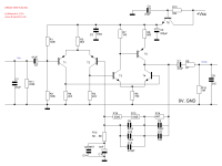
Schematic of the first finale
😉
My layouts are always very special and not everyone's cup of tea. A universal PCB would be great, if you have the time and inclination, go for it.
If this thread mutates / evolved into a free forum project, so much the better - that was and is the intent.
🙂
@Chestnutspread,
do you agree with that? You, I'd like to slowly hand over moderation to you.
Best regards,
HBt.
I don't have to push myself forward, I am very happy about active cooperation and certainly also "Kastanienbrotaufstrich".Will you do it yourself or should anyone else? Wouldn't make sense to later have more different layouts then needed.
I would prefer a kind of universal board, one per channel, which supports the multitrans version as well as single- and symmetrical supply.
😉
My layouts are always very special and not everyone's cup of tea. A universal PCB would be great, if you have the time and inclination, go for it.
If this thread mutates / evolved into a free forum project, so much the better - that was and is the intent.
🙂
@Chestnutspread,
do you agree with that? You, I'd like to slowly hand over moderation to you.
Best regards,
HBt.
Attachments
Outlook
The present project opens up several options:
1) PNP -> NPN & PNP, five bipolar transistors
2) NPN -> PNP & NPN, five bipolar transistors
3.1) Parallel connection, nineteen BJT
3.2) Parallel connection, nineteen BJT
4) Other negative feedback networks
5) Power supply variations
6) SMD versions
The present project opens up several options:
1) PNP -> NPN & PNP, five bipolar transistors
2) NPN -> PNP & NPN, five bipolar transistors
3.1) Parallel connection, nineteen BJT
3.2) Parallel connection, nineteen BJT
4) Other negative feedback networks
5) Power supply variations
6) SMD versions


- Home
- Source & Line
- Analogue Source
- Oread - a DIY MM phono approach