Step by step
I think we should first build a prototype with your board ... what would 10 pieces (or what minimum quantity do you have to order?) cost? - divided by three (catd,Chestnutspread, hbtaudio, ...)!
The power supply and a suitable housing would still be missing; the shielding anyway, against all kinds of interference.
Perhaps "Chestnutspread" would like to coordinate the next steps if he has the time and inclination, or we could go our own ways and share our files and experiences with the OREAD-EQ here on the board.
Regards,
HBt.
PS
It remains exciting 🤸♂️
I optimized the board a bit. Various designs can be used for the film capacitors with pitches of 5, 7.5 and 10 mm as well as axial (Styroflex) capacitors up to 12mm. Radial electrolytic capacitors can have a pitch of 3.5 and 5 mm and max.12 mm in diameter.
(One don't actually need 47µ for input or output capacitors. 4.7µ is sufficient and fits easily as e.g. WIMA MKS2.)
The circuit board contains resistors and capacitors to adapt the pickup used. These can either be selected/connected by jumpers, or the contacts can be used to connect external selector switches, for example.
If one don't need or want that, one could simply ommit the parts or even cut off the circuit board along the dotted line and use connector IA as the input.
There are ground planes on both sides that are connected to each other, but otherwise have no contact with the circuit. They can/must be connected either to the signal ground or, if used, to a metal housing and suitable ground routing.
The cost would be around €50 for 10 boards, including shipping. In addition, there may be Customs fees of an estimated €10 if the package is not waved through directly. There are further shipping costs for shipping the individual boards to interested parties.
So you should expect a total cost of around €15 for a set/2 boards.
But before anyone place an order, there might be other suggestions, designs, or someone might find a mistake, etc.
The power supply shouldn't be a problem, there are countless offers on the internet, and (9 volt) batteries are also suitable for the first test.
(I also have ready-made Gerber files for 317/337 power supplies)

Well,
what else can I say - simply great. I couldn't find a mistake in the routing, but I'd rather look twice. So I'll take two boards, it's a matter of honor.
Greetings,
HBt.
🙂
what else can I say - simply great. I couldn't find a mistake in the routing, but I'd rather look twice. So I'll take two boards, it's a matter of honor.
Greetings,
HBt.
🙂
The routing matches the circuit, this is monitored by the PCB software. However, I transferred the circuit from the working LTspice file to the PCB program by hand. I don't see anything wrong, but when you look at your own drawings, sometimes you just miss something. It would therefore be good if the people involved here also check whether the circuit diagram is OK.
btw, the interest doesn't seem to be particularly huge if you count those who write here 😉
btw, the interest doesn't seem to be particularly huge if you count those who write here 😉
Unfortunately, I also only count 1+1=2. But what the heck, that's just the way it is with DIY and a completely saturated market. But what is not yet can still come - maybe tomorrow.
And once we deliver outstanding measurement values and fantastic sound descriptions as well as magical function descriptions, then the interest will climb up to unimagined heights.
And once we deliver outstanding measurement values and fantastic sound descriptions as well as magical function descriptions, then the interest will climb up to unimagined heights.
Via a power supply unit
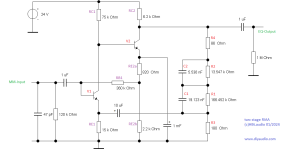
The circuit is very simple, it is not complicated and relatively easy to understand, but at the same time flexible - and that is precisely the intention.
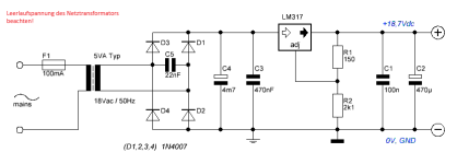
Personally, I would operate both channels with an external power supply of 18Vdc or slightly more, namely 18.7Vdc. So unbalanced - with an LM317 voltage regulator, a charging capacitor of 4700µF/35Vdc, a suitable bridge rectifier, an 18Vac 5VA mains transformer ... and so on.
It is important that the mains transformer cannot be subject to magnetic interference and that it does not hum mechanically and possibly cause its entire environment to vibrate mechanically.
So a little more design creativity is required here than when designing an electrical EQ alone.
The circuit is less half of the battle,
the rest is the challenge!
Regards,
HBt.
The circuit is very simple, it is not complicated and relatively easy to understand, but at the same time flexible - and that is precisely the intention.
Personally, I would operate both channels with an external power supply of 18Vdc or slightly more, namely 18.7Vdc. So unbalanced - with an LM317 voltage regulator, a charging capacitor of 4700µF/35Vdc, a suitable bridge rectifier, an 18Vac 5VA mains transformer ... and so on.
It is important that the mains transformer cannot be subject to magnetic interference and that it does not hum mechanically and possibly cause its entire environment to vibrate mechanically.
So a little more design creativity is required here than when designing an electrical EQ alone.
The circuit is less half of the battle,
the rest is the challenge!
Regards,
HBt.
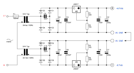
Quick and very simple PSU
The dielectric strength of the electrolytic capacitors should be 35Vdc
and of course the voltage regulator have a small heat sink. A secondary winding with 15Vac could be sufficient for the mains transformer, i.e. the rectified input voltage of the LM317 regulator should be around 22Vdc to 24Vdc (plus ac-ripple) under load - the tiny 5VA transformer works almost at idle.
It's only a possible example for both channel at once.
Attachments

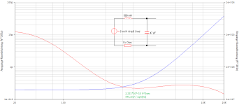
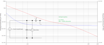
Noise
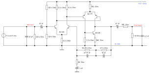
I have three bags of the following old small signal transistors 2N2484, BC177 and BC109. Fifty of each, manufacturer unfortunately CDIL - I'm curious to see if they come close to the old known specifications.
Used in the OREAD-EQ, this housing shape certainly looks very chic and oldschool - it certainly simulates extremely promising.
See for yourself, even with the tiresome R-L input combination as a poor MM replacement, I'm guessing a rated SNR of at least 86dB, at least ... now I have to set up a test circuit again 😉.
HBt.
Attachments

I only ever bought the BC109C gain band - if you want low noise, you want maximum hfe...Noise
I have three bags of the following old small signal transistors 2N2484, BC177 and BC109. Fifty of each, manufacturer unfortunately CDIL - I'm curious to see if they come close to the old known specifications.
Used in the OREAD-EQ, this housing shape certainly looks very chic and oldschool - it certainly simulates extremely promising.
See for yourself, even with the tiresome R-L input combination as a poor MM replacement, I'm guessing a rated SNR of at least 86dB, at least ... now I have to set up a test circuit again 😉.
HBt.
... now I have to set up a test circuit again 😉.
Will you test the multi-transistor version? It would be interesting to know whether there is even any audible advantage over the circuit with single transistors. I fear that there is no advantage.
Then one don't need a large PCB that provides the paralleled transistors.
I currently don't have time to do a test setup myself and my workshop is occupied with metalworking.
And why is that so?I only ever bought the BC109C gain band - if you want low noise, you want maximum hfe...
In this case, the input pair should definitely be selected for maximum hfe because of the relatively large IC of 500µA dc - due to the chaotic shot noise at each PN junction, the path resistance. In any case, the C type is used for our /my present dimensioning proposal*, and C is also written on every small TO-18 cylinder.
Thank you for your advice, I stupidly assumed this.
Would you also like to contribute a layout to the project Mark? That would be great. Or measurements, sound descriptions of your system ..!
Regards,
HBt.
* not written in stone
No, not without a milled test board - unfortunately, since the first corona lockdown, I no longer have a large laboratory or a Protomat at my disposal.Will you test the multi-transistor version?
Well, audibility is one of those things in itself. In any case, the two schematics options are not the same. You have to compare them metrologically - and if that seems necessary, also compare them audibly - and that doesn't mean just listening to your favorite record.It would be interesting to know whether there is even any audible advantage over the circuit with single transistors. I fear that there is no advantage.
There are now a total of four possibilities (two are the 19-BJT-Versions), apart from the vast number of component selection options.
Then one don't need a large PCB that provides the paralleled transistors.
This is precisely why your first universal board is exactly the right approach, as a test board for the two (or four) basic options.
I would start by equipping the five transistor version there, with an asymmetrical operating voltage - measure, listen ... and then (for the sake of the thread and the project) the 19.
That's what I meant by step by step, but now I'm itching to test the NPN-PNP-NPN version with the TO-18 oldschool transistors, so again a breadboard number - or a real board.
Who says A must also say B, where is @Chestnutspread 😢 (hope no accident or illness again)?
Greetings,
HBt.
So, the cheapest system has been ordered and now I'm looking forward to the real practical test:
AT VM95
But having to dismantle the Denon DL-103 to do this is a real pain - but what can we else do for the young?
😉
Circuit designers such as Nick Sukhov, for example, are of the opinion that the cheapest MM system mutates into an MC giant if you only connect the EQ directly to the tonearm cabling and terminate it with a high impedance - is this true? Only time will tell, but I'll say it up front - an MM will never become an MC!
And time has just become a real scarce commodity in times of war and scarcity, omnipresent poverty and environmental catastrophes.
😢
"Kastanie" seems to have disappeared in the dark, what a pity.
The Audio Technica MM system has arrived and is now waiting to be installed, I'm as excited as a flash in the pan - but Percy has drawn my attention to the old school in the
neighboring thread !
Can we call the simplest, two-transistor version OREAD light ?
The Audio Technica MM system has arrived and is now waiting to be installed, I'm as excited as a flash in the pan - but Percy has drawn my attention to the old school in the
neighboring thread !
Can we call the simplest, two-transistor version OREAD light ?
Attachments
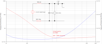
OREAD LIGHT
1.91*10^-13 [V^2/Hz] leads us to a fabulous SNR (rated) of greater than 88dB, this would even beat the Sukhov wonder EQ 😉 .
Greetings,
HBt.
1.91*10^-13 [V^2/Hz] leads us to a fabulous SNR (rated) of greater than 88dB, this would even beat the Sukhov wonder EQ 😉 .
Greetings,
HBt.
(...)
Then one don't need a large PCB that provides the paralleled transistors.
I currently don't have time to do a test setup myself and my workshop is occupied with metalworking.
Hello @catd,
did you have some free time in the meantime to tackle the OREAD project or do we want to bury it (after the unexpected disappearance of the thread initiator)?
Kind regards,
HBt.
😢
Ok, I'll wait for ... (in the meantime I'll play with the original SUPRA).If my test is satisfactory, the boards could be ordered.
I'll get back then
🙂
- Home
- Source & Line
- Analogue Source
- Oread - a DIY MM phono approach