Hi,
I am new to this forum and ended up here in my search for a solution for my broken DIY amplifier. The amplifier consists of two SymAsym 5.3 modules, see attached circuit. It is basically the original SymAsym design with added speaker protection and 2x 4700 uF smoothing capacitors.
Both modules functioned well for about six months. The left module then started showing problems. In the beginning I heard cracking noises and occasionally a loud pop. If I turned up the bass or volume further, the crackling went away. Some time ago the module went silent.
To investigate the problem I wanted to try out my oscilloscope with function generator, so I connected the left module to a 100W 6R. Unfortunately, R2 burned out when I placed a 1kHz sine signal on the amplifier input. I replaced R2 but it burned out again, even at low sine amplitude. So probably another component must be defective. I have desoldered all the transistors and measured them with a multimeter (diode test) and they all seem OK.
Because I have little experience with electronics, I would like to ask for your advice here. Could it be that a transistor is defective even though the diode test is successful? Or could it be other components that are causing problems?
Kind regards,
Jonas
Attachments
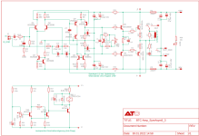
R2 has a few connections to it, the GND on one end, and on the other end, the IN-GND, R14, and R30. The current that burnt R2 could not have gone through either R14 or R30, as they would have got burnt far ahead of R2 would. So it is likely that the potential differential between GND and IN-GND was what took R2 out.
I see. Does that mean the current came from the signal generator? Burning a 1/4 W resistor?
Update: I just found out that the signal generator that is build in my scope is also fried 😢
Update: I just found out that the signal generator that is build in my scope is also fried 😢
Last edited:
It does seem that your test setup is causing R2 to burn out. Make sure that your scope ground and your signal generator ground are tied to the power ground and not to your IN-GND. It could be that your amplifier power ground has some ac or dc voltage relative to the scope or function generator ground. It makes sense to measure some AC and DC levels with a battery powered meter to see if your power supplies are correct. Crackling sounds could be caused by clipping on the output because of bad power supply levels. If you find some bad DC levels then you may have a leaky electrolytic capacitor or a cold solder joint somewhere because the failure seems to be time or temperature related.

I understand now why R2 was fried. Thanks for explaining James361
I will install new transistors and hopefully that will solve the problem.
I will install new transistors and hopefully that will solve the problem.
Haha ive had similar issues, without me noticing R2 ground lift resistor was the lowest impenance path to earth. It burning open killed my input stage a couple times. Now i always make sure that GND has a sturdy low resistance path to earth and this doesnt to keep things safe.
- Home
- Amplifiers
- Solid State
- troubleshooting SymAsym