The PCL82 was probably one of the lamest, dullest and unexciting one-tube amplifier of the sixties/early seventies.
It plagued many cheap TV sets and crap record-players of that era.
According to its datasheet, it was supposed to deliver 3.3W @10% THD with a 200V supply.
Very optimistic...
Even in sim, using exactly the parameters published in the datasheet, it struggles to arrive at 2W.
The reality is even worse.
It is thus a perfect candidate for a long overdue makeover.
I wanted to see how far such a tube could be pushed, whilst respecting all of the key abs.max.ratings, except for one.
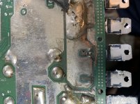
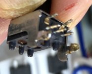
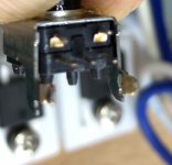
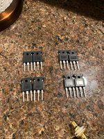
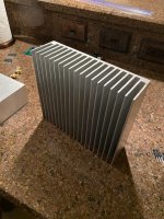
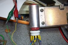
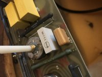
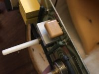
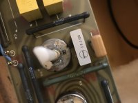
The trick I used is to fit the tube with a cooling clip, attached to a large heatsink, exactly as for a transistor:
The aluminum clip is 1~2mm larger than the tube, and a home-made compound of silicone 145 (high-temp) and MgO ensures the thermal connection and the mechanical protection of the tube.
The heatsinking arrangement keeps the glass surface at ~60°C, instead of ~260°C under free air conditions.
With the max anode voltage of 300V and the max anode current of 50mA, the anode dissipation is 15W, compared to the 7W allowed in the DS: more than the double.
I have tested many amplifier variants, both in sim and reality. The final version is the best-performing in reality (not in sim).
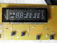
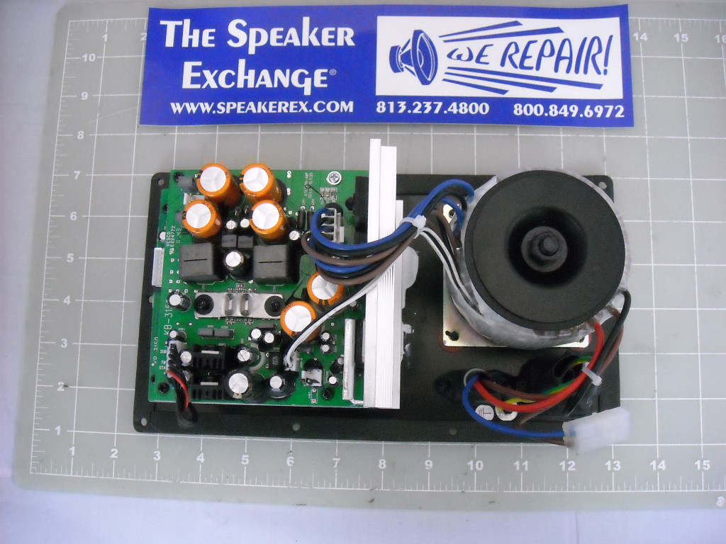
The transformer is salvaged from a TV vertical deflection unit: its characteristics are ideal for for a medium-power SE amplifier.
It has a main, primary winding, a low impedance output compatible with 8 ohm, and an auxiliary reaction winding that can be repurposed as a UL connection.
It is not the first time I repurpose a vertical unit for audio duty: I also did it with a dedicated IC:
https://www.diyaudio.com/forums/chip-amps/280777-funny-chip-amp.html
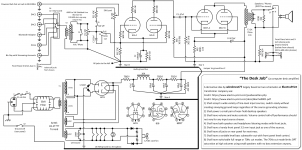
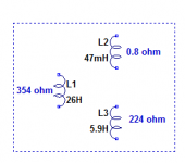
This is a drawing of the transformer (a MBLE BT653): it withstands a secondary current of 1.7A without saturation, which is very generous for this application:
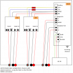
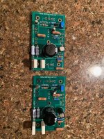
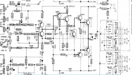
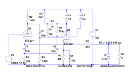
This is the circuit:
The supply voltage is 350V: taking into account the resistive loss in the transformer and the cathode resistor, it result in a 300V anode voltage.
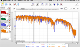
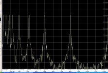
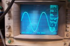
At a THD of 2.5%, the output power is 5.8W. This is the waveform at the anode in those conditions:
At 3W, the THD is 1.1%, and 0.25% @1W.
The 3dB BW at 1W is 10Hz to 26kHz.
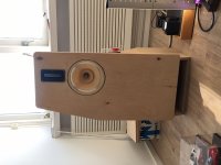
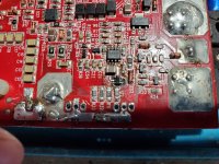
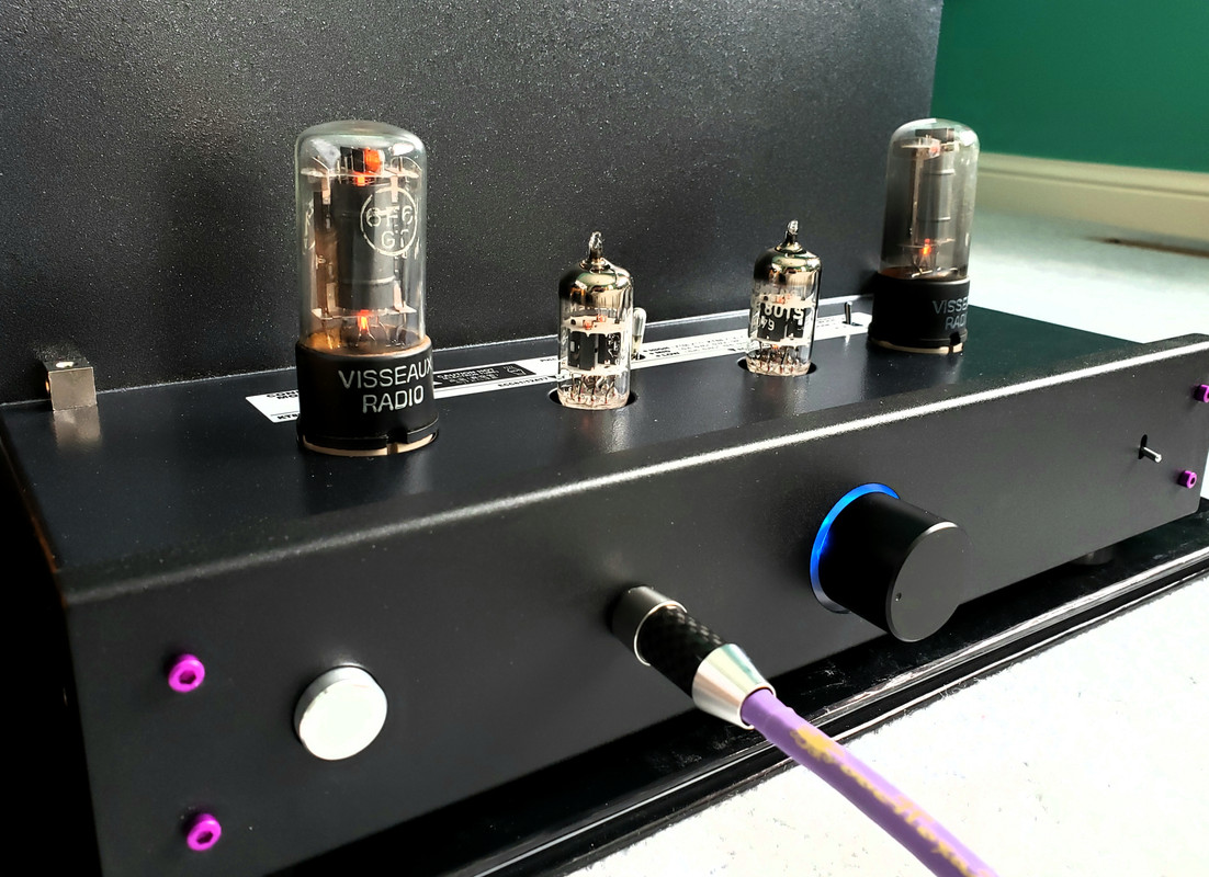
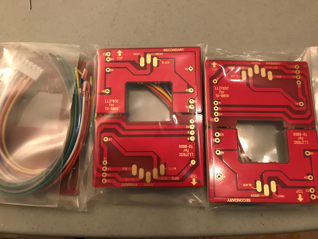
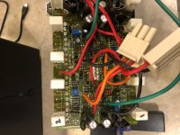
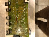
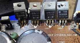
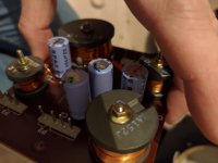
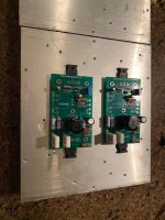
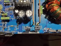
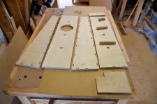
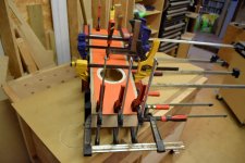
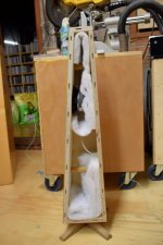
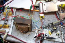
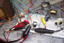
Here are some pics of the breadboard test:
Note that it is a true,
bona-fide tube amplifier: no semiconductor cheat of any kind, not even a diode.


