The PCL82 was probably one of the lamest, dullest and unexciting one-tube amplifier of the sixties/early seventies.
It plagued many cheap TV sets and crap record-players of that era.
According to its datasheet, it was supposed to deliver 3.3W @10% THD with a 200V supply.
Very optimistic...
Even in sim, using exactly the parameters published in the datasheet, it struggles to arrive at 2W.
The reality is even worse.
It is thus a perfect candidate for a long overdue makeover.
I wanted to see how far such a tube could be pushed, whilst respecting all of the key abs.max.ratings, except for one.
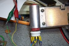
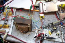
The trick I used is to fit the tube with a cooling clip, attached to a large heatsink, exactly as for a transistor:
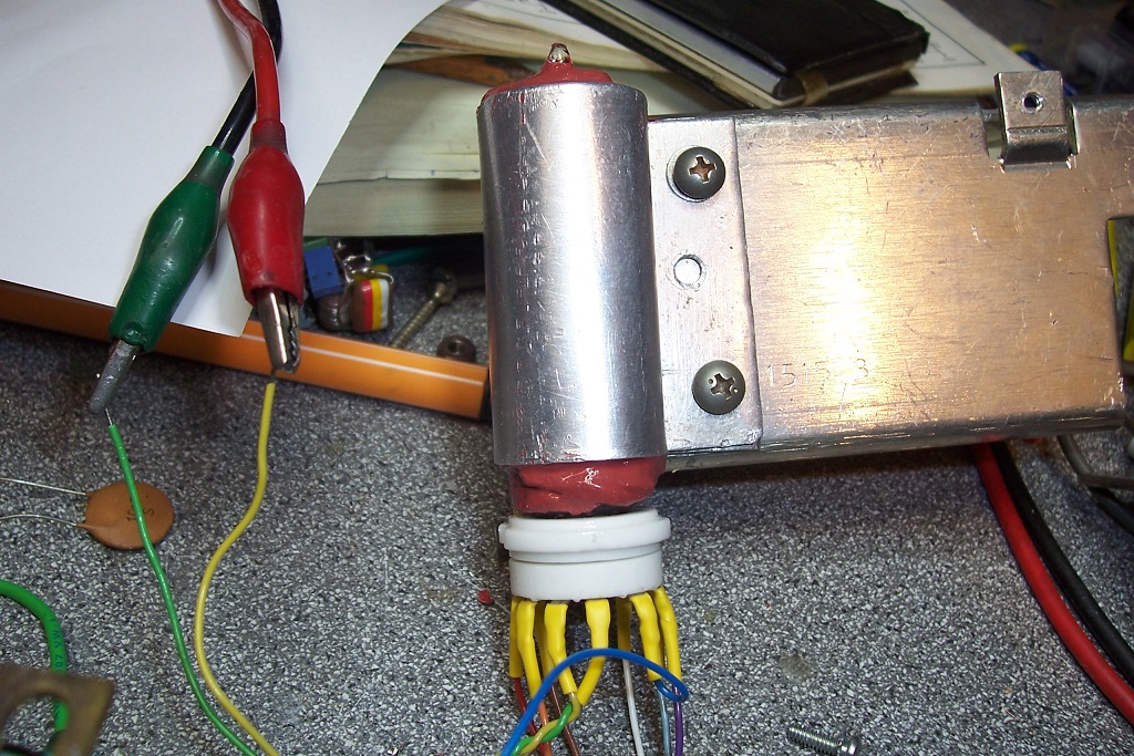
The aluminum clip is 1~2mm larger than the tube, and a home-made compound of silicone 145 (high-temp) and MgO ensures the thermal connection and the mechanical protection of the tube.
The heatsinking arrangement keeps the glass surface at ~60°C, instead of ~260°C under free air conditions.
With the max anode voltage of 300V and the max anode current of 50mA, the anode dissipation is 15W, compared to the 7W allowed in the DS: more than the double.
I have tested many amplifier variants, both in sim and reality. The final version is the best-performing in reality (not in sim).
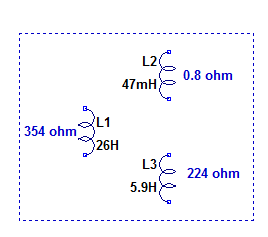
The transformer is salvaged from a TV vertical deflection unit: its characteristics are ideal for for a medium-power SE amplifier.
It has a main, primary winding, a low impedance output compatible with 8 ohm, and an auxiliary reaction winding that can be repurposed as a UL connection.
It is not the first time I repurpose a vertical unit for audio duty: I also did it with a dedicated IC:
https://www.diyaudio.com/forums/chip-amps/280777-funny-chip-amp.html
This is a drawing of the transformer (a MBLE BT653): it withstands a secondary current of 1.7A without saturation, which is very generous for this application:
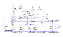
This is the circuit:
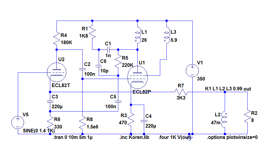
The supply voltage is 350V: taking into account the resistive loss in the transformer and the cathode resistor, it result in a 300V anode voltage.
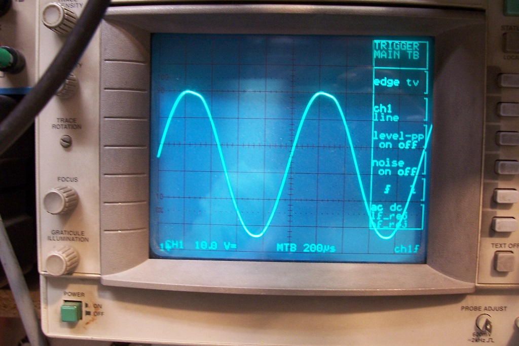
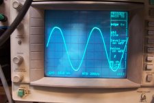
At a THD of 2.5%, the output power is 5.8W. This is the waveform at the anode in those conditions:
At 3W, the THD is 1.1%, and 0.25% @1W.
The 3dB BW at 1W is 10Hz to 26kHz.
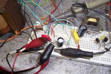
Here are some pics of the breadboard test:
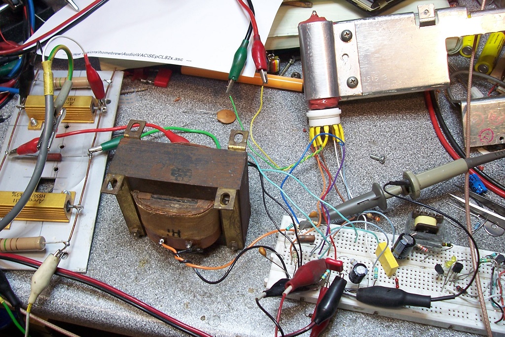

Note that it is a true, bona-fide tube amplifier: no semiconductor cheat of any kind, not even a diode.
It plagued many cheap TV sets and crap record-players of that era.
According to its datasheet, it was supposed to deliver 3.3W @10% THD with a 200V supply.
Very optimistic...
Even in sim, using exactly the parameters published in the datasheet, it struggles to arrive at 2W.
The reality is even worse.
It is thus a perfect candidate for a long overdue makeover.
I wanted to see how far such a tube could be pushed, whilst respecting all of the key abs.max.ratings, except for one.
The trick I used is to fit the tube with a cooling clip, attached to a large heatsink, exactly as for a transistor:
The aluminum clip is 1~2mm larger than the tube, and a home-made compound of silicone 145 (high-temp) and MgO ensures the thermal connection and the mechanical protection of the tube.
The heatsinking arrangement keeps the glass surface at ~60°C, instead of ~260°C under free air conditions.
With the max anode voltage of 300V and the max anode current of 50mA, the anode dissipation is 15W, compared to the 7W allowed in the DS: more than the double.
I have tested many amplifier variants, both in sim and reality. The final version is the best-performing in reality (not in sim).
The transformer is salvaged from a TV vertical deflection unit: its characteristics are ideal for for a medium-power SE amplifier.
It has a main, primary winding, a low impedance output compatible with 8 ohm, and an auxiliary reaction winding that can be repurposed as a UL connection.
It is not the first time I repurpose a vertical unit for audio duty: I also did it with a dedicated IC:
https://www.diyaudio.com/forums/chip-amps/280777-funny-chip-amp.html
This is a drawing of the transformer (a MBLE BT653): it withstands a secondary current of 1.7A without saturation, which is very generous for this application:
This is the circuit:
The supply voltage is 350V: taking into account the resistive loss in the transformer and the cathode resistor, it result in a 300V anode voltage.
At a THD of 2.5%, the output power is 5.8W. This is the waveform at the anode in those conditions:
At 3W, the THD is 1.1%, and 0.25% @1W.
The 3dB BW at 1W is 10Hz to 26kHz.
Here are some pics of the breadboard test:
Note that it is a true, bona-fide tube amplifier: no semiconductor cheat of any kind, not even a diode.
Attachments


Cool.
The heatsink was a common addition to submin valves (6N16B etc) but I have not seen anyone try it with more "powerful" valves.
I wonder what the life expectancy of that valve would be?
Also an interesting scope shot...
What was the THD at that signal level (54Vpp)?
It looks way more than 1%....I can't see any waveform distortion visually, at 1% THD, probably more.
It is nice and purist though, no Si...but I dont mind a little Silicon.
Interestingly, to me, I have improved a pet circuit, by removing the LED cathode bias on the input gain stage - much to my surprise and joy!
Even more of a personal revelation, removing the bypass capacitor,and LNFB from the input stage....giving pretty much identical results!
Well, all of that has to be taken with a pinch of salt: as the title indicates, it is essentially for fun, but I did study the problem (not in depth though).Cool.
The heatsink was a common addition to submin valves (6N16B etc) but I have not seen anyone try it with more "powerful" valves.
I wonder what the life expectancy of that valve would be?
The cathode current is exactly the abs.max., but it is still within the authorized limits.
The same for the average anode voltage.
The Vao is slightly exceeded as the scope shot shows:
There is a X10 probe in circuit, so the pp voltage is 540V, and reaches ~600V on the positive peaks.Also an interesting scope shot...
What was the THD at that signal level (54Vpp)?
That's 50V more than the allowed 550V Vao, but the amp is pushed to the limits and it is a deflection tube, with a 2500V peak anode voltage limit, so it should be reasonably safe.
Honestly, I was surprised to read only 2.5% on my THD meter: I would have thought it was twice as much.It looks way more than 1%....I can't see any waveform distortion visually, at 1% THD, probably more.
If you look carefully, you can see an obvious clipping on the positive peaks... but it amount to 2.5%. Instruments do not lie.
Regarding the thermal stress on the tube, there are a number of issues: an obvious one is the internal temperature.
When the tube is operating "normally", the heat radiated by the anode in the form of IR is intercepted by the glass enveloppe (it is mostly opaque to thermal IR) and then re-radiated and convected.
With the heatsink, the glass gives up all the heat it intercepts, and the rest of the IR radiation is taken up by the silicone and heatsink.
The anode thus sees a body at ~60°C instead of ~260°C, which increases correspondingly the heat transfer. How much exactly? I do not know exactly, and I do not have the means to install a thermocouple inside the tube, but I can use indirect measurements: the heather can act as a sensor.
I accurately measured the current, first with just the heather powered, then with the HV applied (allowing enough time for stabilization).
With 16V, the current without HV was 303.3mA, and 300.4mA with the 15W dissipation added.
That's a 1% increase in resistance. If the tempco of the filament is 0.5%/°C at that temperature (I don't think it is, I need to research the subject), it amounts to a 2°C temperature increase.
The problem is certainly complicated by other factors: electrons emitted by the cathode take some heat with them.
Anyway, the heating does not look dramatic.
There are probably other problems: for example, if all of the glass stays cool, the getter will not be properly activated and will remain inactive.
It was possible to design 100% tube circuits some decades ago, and if you opt for tube circuits today, you should do it the proper way: from a purely rational point of view, tube circuits make no sense but if you chose to build one, do it in a pure, unadulterated way!It is nice and purist though, no Si...but I dont mind a little Silicon.
Interestingly, to me, I have improved a pet circuit, by removing the LED cathode bias on the input gain stage - much to my surprise and joy!
Even more of a personal revelation, removing the bypass capacitor,and LNFB from the input stage....giving pretty much identical results!
I also measured the frequency response: at a 1W level, it is <10Hz to 26kHz (in fact it goes lower than 10Hz).
The 26kHz limit is probably related to the damping network: the 1K8 resistor smoked during the test.
The heatsink assembly looks pretty definitive, impossible to take apart, but it is not the case: contrary to 1-component silicone sealant, the 2-component casting silicone like the 145 has practically no adherence on smooth surfaces, like glass or aluminum.
I include the asc of this version, the only difference is the 560 ohm cathode resistor: I had to use a 470 ohm to arrive at 50mA, as my tube is used and probably a little tired.
An interesting trick possible with the P-series tube is to pass the heather current through the output winding, in opposition with the anode current: this relieves some of the stress on the magnetic core (the heather has to be clean DC, obviously).
In this build, I do not really need it, as the transformer is comfortably oversized.
As the hot resistance of the heather exceeds 50 ohm, the losses are relatively minor
Attachments
An interesting trick possible with the P-series tube is to pass the heather current through the output winding, in opposition with the anode current: this relieves some of the stress on the magnetic core (the heather has to be clean DC, obviously).
Then you need to feed the heater from a CCS (make the heater circuit high impedance), unless you want to lose output power into it.
You're a lucky guy 'cause you don't see what the plate does inside your heatsink clamp 😀.
Anyway, good idea! Another option might be to oil or water cool the envelope (and just the envelope!).
Best regards!
Kay,
I have seen that some valves were cooled this way.
Devil advocate!!! Now I need to try it!
Elvee,
It wouldnt be all that hard to mount a octal socket in a jam jar lid, and mount it upside down, in some oil (lots of transformer oil here...)
In that case, the valve could be immersed, pins, base and envelope, in dielectric transformer oil!
When using oil you can improve use connecting pipes and an oil container, a heat exchanger, etc. for continuous cooling instead of boiling oil. I did something similar with a TBW6/6000 water cooled tube, with 5000 volts @ 1 Amp. However this was a HAM device, no audio. Still have the tubes...
Regards, Gerrit
Regards, Gerrit
The PCL82 was probably one of the lamest, dullest and unexciting one-tube amplifier of the sixties/early seventies.
It plagued many cheap TV sets and crap record-players of that era.
And because thats the most worst tube on the planet, it has a cult of followers in japan. Even Shindo San used to use this tube extensively for his amps. Bad, bad tube.
You must be very lazy or late never have heard of its merits.
I guess the E/PCL82's era was in the 1950ies, not even in the 1960ies, and surely not in the 1970ies. We can date it's end at least in TV services when it's purpose was split into two branches of more specialized tubes, the dedicated frame deflection tube PCL85 (soon to be replaced by PCL805) and the dedicated audio tube PCL86. Does anyone know when both appeared on the market?
Best regards!
Best regards!
........ it's purpose was split into two branches of more specialized tubes, the dedicated frame deflection tube PCL85 (soon to be replaced by PCL805) and the dedicated audio tube PCL86. Does anyone know when both appeared on the market?....
According to R-type.org:
The ECL86 was one of the last triode plus output pentode valves designed and was released to the market in 1962. Uses were in domestic radio and audio equipment. Normally in single ended output stages for radio-grams and tape recorders. The design proved popular in low cost stereo systems. The ECL86 was preceded by the ECL82.
This exhibit is my spare for the TK14 tape recorder that I have had since December 1963.
The thin glass tube envelope is 20 mm in diameter and, excluding the B9A base pins, is 72 mm tall.
References: Datasheet & 1040. Type ECL86 was first introduced in 1961.
The ECL85 is purpose designed for frame generation in television receivers. The triode provides the oscillator and the pentode is optimised for pulse output operation into the magnetic load of the scanning coils.
The thin glass tube envelope is 20 mm in diameter and, excluding the B9A base pins, is 68 mm tall.
References: Datasheet & 3002. Type ECL85 was first introduced in 1961.
The ECL82 is described by Mullard as an audio triode plus output pentode. We also have data from Brimar, in that the valve is described as a triode plus beam tetrode. The Mullard version will use the pentode configuration.
The triode section has a amplification factor of 70, and this valve was much used in record players with crystal pickups. The latter had a relatively high output and when coupled with the single ended pentode output stage made effectively a single valve design. Only a rectifier was required to complete the line-up. In the similar PCL82 form with 300 mA heaters this valve was a most popular choice for the audio stages of domestic television receivers.
The thin glass tube envelope is 20 mm in diameter and excluding the B9A base pins the valve is 68 mm long.
References: Datasheet & 1040. Type ECL82 was first introduced in 1956.
 !
!Heat Sinks for Vacuum Tubes
These were designed by Bill Perkins of PEARL (Perkins Electronic Acoustic Research Laboratory) of Calgary, Alberta.
PEARL Tube Coolers
These were designed by Bill Perkins of PEARL (Perkins Electronic Acoustic Research Laboratory) of Calgary, Alberta.
PEARL Tube Coolers
Ideally, yes but with P-series, the resistance of the hot filament is ~53 ohm, to be compared with the 8 ohm load.Then you need to feed the heater from a CCS (make the heater circuit high impedance), unless you want to lose output power into it.
The loss is minor, and the increase in heating when the audio level is high is very marginal with musical signals; anyway, it is just an idea I throw in the air.
I have refined my calculations: at the operating temperature of the filament, the tempco is ~0.082%/°C, which translates into a ~12°C rise at the heart of the tube.You're a lucky guy 'cause you don't see what the plate does inside your heatsink clamp 😀.
Anyway, good idea! Another option might be to oil or water cool the envelope (and just the envelope!).
Best regards!
I don't think it is larger than for a tube operated in the regular manner, it might even be smaller.
I may make further tests on a non-heatsunk tube for comparison.
Kay,
I have seen that some valves were cooled this way.
Devil advocate!!! Now I need to try it!
Elvee,
It wouldnt be all that hard to mount a octal socket in a jam jar lid, and mount it upside down, in some oil (lots of transformer oil here...)
In that case, the valve could be immersed, pins, base and envelope, in dielectric transformer oil!
Oil or water is another possible option, but I preferred to avoid dealing with liquids: my preference goes for purely static, dry solutions.
Of course, with really high power, a continuous flow is required, but it becomes seriously complicated for lowish power levelsWhen using oil you can improve use connecting pipes and an oil container, a heat exchanger, etc. for continuous cooling instead of boiling oil. I did something similar with a TBW6/6000 water cooled tube, with 5000 volts @ 1 Amp. However this was a HAM device, no audio. Still have the tubes...
Regards, Gerrit
I experienced first hand the lousy sound of those cheap amps, first as a toddler, then as a teenager, and it made my ears bleed...And because thats the most worst tube on the planet, it has a cult of followers in japan. Even Shindo San used to use this tube extensively for his amps. Bad, bad tube.
You must be very lazy or late never have heard of its merits.
I have been marked for life
Great! it wonderfully proves my pointThese were designed by Bill Perkins of PEARL (Perkins Electronic Acoustic Research Laboratory) of Calgary, Alberta.
PEARL Tube Coolers
Here are some other possibilities I explored to use the auxiliary winding.
The version I posted gave the best results in reality
The version I posted gave the best results in reality
Attachments
I made the test on another tube, without heatsink: with the heather only, the current was 295.5mA, decreasing to 293.2mA with a 7W anode dissipation, a ratio of 1.007844, compared to 1.009653 with 15W + heatsink.I don't think it is larger than for a tube operated in the regular manner, it might even be smaller.
I may make further tests on a non-heatsunk tube for comparison.
The increase in resistance is thus 0.78%, against 0.96%: this probably means that 15W is slightly excessive for this arrangement.
The supply voltage should be reduced, to bring the dissipation in the region of 12~13W.
With liquid cooling, 15W would probably be manageable, but it is far less convenient.
The circuit itself is OK: it is good and stable, and makes an effective use of the available loop gain. It can also help recycle some orphan, salvaged transformers in a creative way
With liquid cooling, 15W would probably be manageable, but it is far less convenient.
I would have thought that liquid cooling would be easy to try if the tubes were mounted upside down and suspended over a trough of water
316a
For an informal test, maybe, but for everyday use liquids are a nightmare.
Even for "fun" projects, I try to remain down-to-earth, practical.
Even for "fun" projects, I try to remain down-to-earth, practical.
Hehe the practicality of liquid cooling is problematic, for a DIYer to realise, beyond informal tests!
However, I do wonder if certain tubes would benefit more from this type of cooling enhancement (either heatsink or fluid cooling)
Specifically, those metal cases tubes, or something with darkened/smoked glass envelope.
Being as from.an experimenters point of view, the limitation on dissipation is ultimately the efficiency of radiation of heat from the electrodes, and I'd hazard a guess that the black/smoked glass or metal envelopes would be more efficient at taking radiant energy away from the electrodes.
I attempted a first test, but something went wrong: at first, when the HV is applied everything looks normal, but after a few tens of seconds the current begins to rise, and things get quickly out of control.Hehe the practicality of liquid cooling is problematic, for a DIYer to realise, beyond informal tests!
I am not sure what the problem is; maybe a faulty tube, or maybe I inadvertently splashed some water into the pins region.
I will retry with another tube
At thermal wavelengths, the glass acts almost as a black body. Metal without surface treatment will reflect back some of the energy. Metal is also a better thermal conductor than glass, but for the area/thickness ratio of a tube, it probably doesn't matterHowever, I do wonder if certain tubes would benefit more from this type of cooling enhancement (either heatsink or fluid cooling)
Specifically, those metal cases tubes, or something with darkened/smoked glass envelope.
Being as from.an experimenters point of view, the limitation on dissipation is ultimately the efficiency of radiation of heat from the electrodes, and I'd hazard a guess that the black/smoked glass or metal envelopes would be more efficient at taking radiant energy away from the electrodes.
Last edited:
- Home
- Amplifiers
- Tubes / Valves
- Having some fun supercharging a E/PCL82 amplifier