conrad johnson premier one

just revised amp new octal sockets and kathode resistor 12 pcs each
inside electrolithics
tungsol 6550 tubes
to pick up near Paris
3500 euros
cj premier one - Google Drive

Attachments

  • 100_0138.JPG
    100_0138.JPG
    400.6 KB · Views: 270
  • 100_0134.JPG
    100_0134.JPG
    426 KB · Views: 262
  • 100_0136.JPG
    100_0136.JPG
    565.2 KB · Views: 269
  • 100_0137.JPG
    100_0137.JPG
    602.9 KB · Views: 253
  • 100_0157.JPG
    100_0157.JPG
    552.8 KB · Views: 255
  • 100_0140.JPG
    100_0140.JPG
    595.7 KB · Views: 142

Another CA A5 thread

Hi everybody, long time no see
After almost 4 years of absence I'm trying to slowly do something electronic related and need some help with a very strange issue that is driving me up the wall.
Cambridge Audio A5
Original fault was a failed power transformer that was replaced with the wrong one, someone fitted a 25-0-25 instead of the 30-0-30 original one but it worked.
I bought it before my health problem and was in the wardrobe until last week.
Current issue:
Sound volume to low, need to turn up to 12 o'clock just to have a moderate sound level, I checked everything, every single resistor even put opamps from pre and buffer on bases to make it easier to replace, replaced them (NE5532) to no avail and just don't know where to look any more, the amp works fine just the sound level is to low, I repaired so many of this amps (A4/A5/A300/A500) and never seen anything like this.

ESP32 driven PGA2320 preamp/IO switcher

Before starting the project, first I would like to check if similar thing already exists, and secondly, if it makes sense at all...

I plan to base it on LDR Pre MkII code:

https://www.diyaudio.com/forums/ana...dr-pre-mkii-ldr-volume-control-switching.html

which means 2.42" OLED display, dual rotary encoders, IR remote, 4 input channels and 2 output channels switched by relays, only PGA2320 instead of LDRs. Additional features available from ESP32 would include web interface for channel switching and volume control, and potentially even A2DP BT audio streaming.

Why PG2320 instead of LDRs? It's simpler to use, much lower distortion and coloration, which some might prefer as opposed to LDRs. I heard PGA2320 in M3Si and I liked it a lot.

100W 8RJ resistors

I'm building a dummy load device for amp testing. I ordered 4 100W 8 ohm, wire-wound resistors from a vendor in Hong Kong (the gold aluminum jobs). They just arrived and are much smaller I expected; 59 mm long. I Googled a bit and see that other 8RJ resistors are the same size - so, it's my fault. Should I get something heavier? With shipping, they were only $15, so I'm not in too deep.

LifePO4 Battery Build Instructions/Parts

Hi, I have used pre-built batteries (batteryspace) to power my boomboxes before with the best luck coming from those based on 26650 LifePo4 batteries. I'd like to build one myself but due to space restrictions, I can only use 4 18650 batteries.

Can anyone point me to a build thread on this type of battery? I'd like to incorporate a BMS.

I searched here and posted on the class D forum and got some suggestions for parts, but no references to a thread that shows wiring diagrams etc.

Any thread or video suggestions are appreciated.

Star grounding and metal cases

Dear fellow users,

I'm keen to understand star grounding more - specifically asking some practical advice for when using metal (or otherwise conductive - salty ice anyone?) enclosures.

Let's say you are building a stereo preamp with a linear power supply in it. The 'power' ground is connected to the mains earth. If you are using a metal chassis/project case - you would also ground the case (usually with a wire with a lug on the end and a machine screw to the case). This is important for safety reasons (if a live wire should break loose and touch the enclosure it shorts to ground rather than shocking the user). However, I also have my "signal" ground to account for. Most potentiometers/phono jacks have a grounded casing which will make contact with the project enclosure. This means (inconveniently) that there is some internal connection of grounds at the desired star point, but also ground connections all over the place through the casing. How does one avoid this in practice? Use plastic bits (ugly)? Use wood bits (fire hazard)? Put a low resistance between earth and the case (potentially dangerous/fine but illegal, I don't know)?. Something else?

Cheers in advance for suggestions.

What Substitute For A PQ05RF21 Regulator

Hi,


I'm currently repairing a Roland digital reverb unit. I suspect a problem with the unit's power supply so I'm looking to replace the various components. The unit uses a PQ05RF21 voltage regulator. Are these still available? What would be a suitable substitute?


Also, there are a few of these listed on ebay - I'm a bit suspicious about these being the real thing - any thoughts on this?


Cheers,


Chris

Project with Beyma 12xa30nd coaxial driver

Hi!
I am new to the diy scene and this will be my first project.
For the moment i have a lot of doubts about what path to choose.

Can somebody please help to decide what kind of speaker would better fit the Beyma 12xa30nd driver:

Big TQTW?
Big Bass reflex?
Small bass reflex?
Back wave horn?

It will be used as an hifi speaker, at home, in a moderate sized room (+/-36sqm) to be played at moderate levels.
I want high sensitivity in order to use low wattage amplifiers (8 a 40W)

I am looking forward for your feedback.
Thank you in advance for all the support I hope to get. 🙂

two-stage NIC amp without global feedback

Another design I've come up when thinking further on negative impedance converter topologies:
NIC_2_stage_circuit.png


Ignoring the input buffer, this is a 2-stage amp. Standard CFP output stage fed from a bootstrapped opamp implementing a NIC with gain of 20.

The input point at XXX has a -2k impedance, which is why the buffer is added (although it simulates fine without it, if driven from a low impedance).
The -2k is the difference between the R4 and R2, as the non-inverting input is impedance converted to -20k (reflection of R2).

The inputs to the opamp (grey line below) swing at half the output voltage, allowing the overall opamp supply range (cyan/magenta) to swing completely above and below ground:
NIC_2_stage_waveforms.png

(There is a 33V zener to define the opamp supply voltage plus decoupling cap)


Square waves are handled fairly well (a little bit of raggedness, hard to see on the 10kHz plot)
NIC_2_stage_square.png


I've not tried this for real yet - I suspect it will be fussier in real life than simulated. And it will need a proper bias circuit.

R21/C8 form a snubber needed to shunt any unwanted HF feedback via the bootstrapping path leading to oscillation - the simulation needs it, I suspect this will be somewhat different in reality.

FS: 2 800VA transformer (EU only)

I offer 2 toroidal transformer, manfuctured by Toroidy.pl.
Manufacturing date was April/2020.

They are just used in a prototype build.
I wanted to use them for a F5, but now I decided to build a much larger Amp, so I have no use for them.

Primary: 230V
Sec 1: 20V, 19A
Sec 2: 20V, 19A
Sec 3: 5V, 2A
Sec 4: 5V, 2A

I sell both for 200EUR plus shipping.

Attachments

  • IMG_4059.jpg
    IMG_4059.jpg
    70.3 KB · Views: 270
  • IMG_4060.jpg
    IMG_4060.jpg
    84.9 KB · Views: 263

Replacing Logitech z2300 speakers!

Hello, at first I want to say that I am very very new to music equipment!


Yesterday my Logitech Z2300 satellites blown and I am thinking of replacing them (subwoofer stays). So I have 2 questions:
1. What satellites do you recommend for Logitech Z2300 subwoofer (price range 50-80$)?
2. Does subwoofer have an amplifier inside or I need a new one?
I tried to surf and found these, http://www.amazon.com/Sony-SS-B1000-8-Inch-Bookshelf-Speakers/dp/B000OG88KY. Are they gonna suit?
3. A new good amplifier would increase my sound quality or power?

Thanks for your answers!

Tubelab SE 300b Build Thread

Finally started my TSE build tonight and thought I would document it and ask questions here. I soldered in R1-R7.

When soldering R7, some of the solder might have flowed onto the adjacent pad for R6, but I can't really tell. It could just be some flux in there (or it could be nothing). If I read the schematic right, R6 and R7 are actually connected at this point.

Anything to worry about? Should I try to clean it out?

Here's a closeup image.

r6-r7-cropped by jeffdrouin, on Flickr

Not my cleanest work.

Recommend opamp with low supply current.

Probably a dumb question, I know I can find out myself, but the hours of googling that will take...Perhaps there is an opamp guru here that knows?
So for next project I figure why not a small battery powered thingy. Opamp based and I want to try very low power consumption and very small size, which is totally new to me.
Went looking at Mouser and Digikey trying to select which opamp. I know about some of the audio opamps, but not if there are any good ones that have very low power consumption.
Criteria:
Unity gain stable.
Low drift/offsets (precision class)
GBP 20MHz or more
SR > 8V/us
Small SMD, 5 or 6 pin SOT23 or similar. Pins on the outside, not under the package.

Any suggestions?
I am considering OPA322 or LT6233... ?

Bob and Alice

Sort of a crazy thought, I do not believe in relativity, speed of light limit(speed of dark), dark energy and so on.
But in modern quantum non-classical physics "spooky action at a distance"
is seen within many experiments.
So looking at the current mirror, could it be a non-local entangled pair?
ie Bob and Alice.

(I've read may discriptions of the current pair)

Attachments

  • FC48A00A-0874-4DFD-99D4-7BFBAE5D6FC9.jpeg
    FC48A00A-0874-4DFD-99D4-7BFBAE5D6FC9.jpeg
    176.2 KB · Views: 698

fs: Minidsp 2x4 unbalances (2 units)

Hello.
I do have 2 minidsp 2x4 unbalanced for sale.
One of them is boxed and the other one is the unboxed version as you can see in the pictures.

Both of them are in perfect working condition as well as very good cosmetic condition.

I can provide the following plugins with the boards:
MiniDSP_2wayAdv_110
MiniDSP_4wayAdv_109
MiniDSP_Xover_2way_102

I will ask 60 euro for each board
If you buy both boards the price will be 100 euro.
PP fees + Shipping to be added


An externally hosted image should be here but it was not working when we last tested it.

An externally hosted image should be here but it was not working when we last tested it.

An externally hosted image should be here but it was not working when we last tested it.

An externally hosted image should be here but it was not working when we last tested it.

An externally hosted image should be here but it was not working when we last tested it.

An externally hosted image should be here but it was not working when we last tested it.

An externally hosted image should be here but it was not working when we last tested it.

An externally hosted image should be here but it was not working when we last tested it.

End-to-end speaker enclosure modelling design software

hi friends

I have been studying basic of acoustics and various jounels and other spreaded I formation for speaker design and trying to replicate some already available horn speakers ich as cornu spiral and T-Line

Now I want to go for a development of a end to end 3-Way Horn speaker, with horn shaped enclosure therefore I need enclosure design modelling software name where I can work end to end.
I have heard name OF ANSYS & COSMOL but Horn Enclosure section I couldn't find. I only need to go with enclosure design with available component and tweeter speakers.

I have seen Winspeakerz, Bass Box Pro 6 and Term Pro etc but they doesn't seems comprehensive and spending time to learn them and design a commercial product doesn't seem feasible to me

I am willing to spend time for this and pay for basic version.

Help from Ametures is required to go for end to end software.

My DIY speakers all sound kind of muffled

Hi, as this trend of DIY speakers with those tda7492 and tpa3116 amp boards is growing, I gave it a shot and started building some speakers. I built a small one with this drivers (AIYIMA 1pcs 1.5 inch full range 4ohm 10W 40mm Fever Bluetooth wifi speaker strong neodymium loudspeaker-in Portable Speakers from Consumer Electronics on Aliexpress.com | Alibaba Group to clipboard) and this 2*5w amp ( Bluetooth Power Amplifier Module 4.0 Audio Receiver CSR8645 APTX Dual 5W Speaker Audio Amplifier Lossless Band Talk Function-in Integrated Circuits from Electronic Components & Supplies on Aliexpress.com | Alibaba Group to clipboard), but in the end, it all sounded muffled, than I build a bigger box, and bought another pair of the same drivers and used this amp (2 X 8 Watt Class D Bluetooth 4.0 Audio Amplifier Board - Tsa2110a | eBay), but I'm the end, it also sounded muffled. The design was a sealed box with a passive radiator, without any foam or stuffing inside.
I thought it was due to the drivers so I bought different bigger drivers
I build a box with the front panel of this size 33cm*12cm. I used a 25w 7492p amp and tried it with the box closed and with the back panel with a little gap and in both ways, it sound muffled... What am I doing wrong??? Is it the drivers? The design? The amp?? The lack of stuffing? Every speaker is sounding a bit muffled and distant like the music is coming from inside a box.. really weird

6J1 FU32 3.5W+3.5W DYI kit product of china

I am totally beginner, Just followed manual but sound is poor. so small and distorted. Tubes are turned on normally but sound is very poor. What can I do check for trouble? anyone who experience may helpful.


Sorry, I forgot 2ea ground wiring. Try now...

Now sound is wonderful. Thanks....

Attachments

Non-switching complimentary output stage

Sometimes ,you need to circum navigate the planet to find out, it was just behind your shoes.

842997d1589190924-switching-complimentary-output-stag-swiching-comp-jpg


842996d1589190924-switching-complimentary-output-stag-switch-jpg


The quiescent bias current is 145ma . As you can observe on scope , the minimum current falls to 90ma at 32.8 vp on 8 ohms with 33vp input 1khz, with Dtot of 0.04% .

Attachments

  • non switch.JPG
    non switch.JPG
    49 KB · Views: 2,821
  • NON SWICHING COMP.JPG
    NON SWICHING COMP.JPG
    81.9 KB · Views: 2,896

What is the best/recommended way to wire the bias trim-poti ?

Hello,

could you guys please tell me the recommended/best way to wire a bias trim-poti for a KT88 / KT120 PP amp ?
It seems to me the version A in the attachment is more reliable and the version B has a constant RC, but I do not really know if I should trust the PNP ? I know about the problem with the wiper of the potis.
Any suggestions for a better schematic are welcome.

Attachments

  • Bias_pot.asc
    Bias_pot.asc
    3.7 KB · Views: 89
  • Bias_pot.jpg
    Bias_pot.jpg
    180.4 KB · Views: 433

A most mysterious (to me) power transformer

Hello again, I 've recently acquired a power transformer in order to feed a Linkwitz-Riley crossover and/or solid state preamp. Both can work great at +-15VAC. The device works, but I can't understand how it does it, as you will soon see.

So here's my power chain:

1) LED power supply, input 240VAC, output 24VDC
2) DC Voltage regulator with which I can decrease or even increase DC voltage
3) Mysterious power transformer 24VDC input, +-15VDC output and ALSO an intermediate dual AC output (that's the mystery part)
4) L-R crossover board (or discrete solid state preamp)

Now, the power requirements of the L-R board should be very low, about 2-3VA. The manufacturer states that it works within a range of dual 14VAC to dual 19VAC. Now to number 3), the mysterious device.

attachment.php


The device's stated purpose is to turn 24VDC to +-15VDC. However, I got it for its intermediate output, which is marked as dual AC. Only recently after inquiring with the manufacturer I realized this must be some not very supported output, and the only reason for this intermediate dual AC conversion is to create the +-15VDC output.

However, powering the LR board (~2-3VA) with this output does work. It can also turn on my pre which has a bit higher power demands(~10VA).

I'm certain most of you have recognized the board's design, I shall now be a bit more revealing. If I feed the device with 24VDC, this is what I get with my recently acquired True RMS multimeter at the dual AC output.

attachment.php


Yes, the reading is correct, it's a miniscule 15mV but with frequency of a whopping 20KHz! The device works ok because the dual DC output is pretty much spot on at +-15VDC.

Can you help me figure out what this board's principles of function are? I mean roughly how it is designed and how it works. Then I can see if and how I can utilize the intermediate dual AC output for powering stuff (safely). I'm pretty sure things flow from top left to top right to bottom right to bottom left. I suspect the tiny width voltage is used to feed the two caps near the +-VDC output, but can I use it elsewhere? Thanks for any insights/help.

Attachments

  • DSC_0009.JPG
    DSC_0009.JPG
    98.4 KB · Views: 1,322
  • aiyima.jpg
    aiyima.jpg
    93.6 KB · Views: 1,320

How would be a good proportion graphic of distortion for triodes ?

How would be a good proportional graphic of distortion for triodes ?


Are there some general rules to achieve the desired profile?
Use the Bias point in the symmetric part of the graph?
less or more current, more or less voltage?
Put the bias somewhere asymmetrical on the curve chart.
I read that may be, if the distortion is using the bias in symmetric curves, the 3rd harmonic and the 5th increase.
And putting the bias point on an asymmetric point of the curves graph gives 2nd and 4th order distortion.

I have doubts.

My amp sounds like a good Mosfet today, not a DHT.

I am using 6S45p and 6550 triode connection.


I bought a FFT spectrum analyzer, just to see how is the distortion pattern
today.

The chart below is just an example. It is not my amp.

Attachments

  • d2d3.gif
    d2d3.gif
    8.7 KB · Views: 243

smooth end to a circle cut with router

When using a router and a circle jig what do you do when you get to the end of the cut to keep it smooth?

As the last section of wood gets cut from the circle the router can move anywhere it wants and so the last 1/8" or so of my circle usually ends up with a bit too much or too little cut.

When I have easy access to the bottom of the board and don't care about damage to that side I have screwed a piece of wood across the circle to hold it in place. But that isn't always an option.

Anyone have any tricks or is it just a steady hand?

Elecrolytic Capacitor Replacement Dilemma

Hello - I am wanting to replace the 4 larger can electrolytic capacitors in the power supply section of my NAD 2100 stereo amplifier which is about 30 years old. Two of these large electrolytic caps are the 4 pin type consisting of a terminal for the positive, a terminal for the minus, and 2 terminals for mechanical support. I found 2 possible replacements on Digi -Key and the spec sheets for both of these caps have the following cautions from the manufacturers:

"Use the blank terminals for mechanical support only. The blank terminals must not be connected to a solder trace on the PC board, but be electrically isolated from the negative or positive terminal."

"Use dummy terminals for mechanical support only. Make no electrical connection because they resistively connect through the electrolyte to the negative terminal."

My dilemma is that when I look at the underside of the circuit board I can clearly see that these support pins of both of these capacitors are soldered onto traces that lead back to the negative terminal of the capacitors and clearly this is in complete contradiction to what the manufacturers are saying.

Can I safely install these 4 pin capacitors in the same way as the original ones are soldered in?

Also, the second caution statement seems to contradict itself, because it says that the dummy terminals resistively connect through the electrolyte to the negative terminal. I am not sure what "resistively connect" means, but I assume that there would be continuity between the dummy terminals and the negative terminal?

Could have the NAD designers overlooked what the capacitor manufacturers are warning against, or possibly that the way the capacitors were made 30 years ago allowed for the support pins to be soldered to traces that went to the negative pin? Or, could it be that the capacitor manufacturers are just "over warning" against a potential degradation that can happen over time and / or just trying to prevent lawsuits?

The amplifier is working well and sounds good, but I am reading that old electrolytic capacitors should be replaced. I am wanting to replace these power supply capacitors to prolong the lifetime of this amplifier and to prevent potential damage that could occur if these capacitors could blow up or get shorted. These capacitors seem to be very slightly rounded (convex) at the top but there are no signs of leakage.

Also, would it be reasonable to just replace these 4 large power supply capacitors and leave the other 30 very small electrolytic caps alone, or should I definitely replace all electrolytic's which would be very tedious?

Any suggestions or input would be very much appreciated and thank you for your time.

I need help with resistors in my GM70 build

Ok, I need some help. When Kegger and I worked out this schematic he marked a couple resistors with watts and said the rest were .5 w or 1w or something like that. What watt should they be? P s, I added the 1W for the ones I dido know about.

location value value

Resistors

2 R2 220 1w
2 R3 1k 1w
2 R4 800 15w
2 R5 100k 1w
2 R6 22 1w
2 R7 22 1w
2 R8 510 1w
2 R9 510 1w
2 R10 68k 10w

Caps

2 C1 0.47 1000v
2 C2 50 200v
2 C3 220 10v
2 C4 47 ???

Attachments

  • Kegger final version.jpg
    Kegger final version.jpg
    45 KB · Views: 246

just a thought about arranging PCB's

Hi!

While contemplating nice builds (Salas UltraFSP RIAA...), a silly thought about arranging PCBs crossed my mind:

why not placing them vertically, back to back?
of course it is about fanciness 😀, but also about some technical details:
How close could 2 PCBs be put together?
What is the best way to arrange them anyway? (I think, enabling short wires is an argument, and probably more important, keeping signal away from everything else?)
other things to consider?

thank you!
david

Cambridge R50 Front Panel

A few years ago I purchased the Famous/Infamous Baobab Cambridge R50s, from someone near Langley Mill, and set about restoring them. Its been a very stop/start story and its time to do some more work.
Is there anyone in the UK who makes/can make the front panels for these speakers. The originals are fitted with openings for the Racetrack B139s and I would like to fit the later type. Any info would be gratefully received.


I also wish to get rid of/ pass on, the original Baobab expanded metal speaker grilles. Anyone interested? I am in the SK22 postcode, just south of Stockport.


Thanks for reading.

Attachments

  • cambridgeR50.jpg
    cambridgeR50.jpg
    54 KB · Views: 126
  • Baoba R50s.jpg
    Baoba R50s.jpg
    19.6 KB · Views: 153
  • 20200616_123112.jpg
    20200616_123112.jpg
    1.1 MB · Views: 119

Noise from bluetooth amplifier

Hi all,

I'm not at an electronics expert, so this might sound like a dumb question.

I have bough one of this TDA7492P-Bluetooth-Amplifier-Wireless-Receiver and I'm actually quite surprised it works with a decent quality, and I can finally use a pair of old forgotten speakers with it.

However, I have this strange issue: every time I start playing a song, this weird noise that I could only describe as somebody tapping on a mic quickly for one sec happens.

Does anybody know what this is ? Can I do something about it ?
I have checked the other posts about this board but I don't see a similar issue.

Thanks in advance !

Loud “snap” when turning on Sony TA-1150 integrated

Two days ago, I could not resist temptation and bought a Sony TA-1150 integrated amplifier. Advertised as being in working condition, and it is but exhibits a loud “snap” or “pop” when turning on the power switch.

It was not possible to audition the amp at point of sale, I was unprepared and the owner had no signal source with compatible plugs. All I brought along was a DMM to check DC offset which was low enough - 16mv & 30mv.

The owner was a personable fellow and I accepted his saying he successfully used the amp a number of years before retiring it some 5 years ago. The price settled on was about what the amp sold for brand new in 1973. I paid such a price because the model is not common and was the first brand new stereo amp that I ever bought.

Once at home and hooked up I confirmed it was as described meaning it worked. A pleasant surprise was none of the controls were noisy at all and that includes two sliders.

However, as the thread title states, there is a loud noise when turning on. Having previously lived with a TA-1150 I can attest that is not typical.

Gleaning information from forums, a capacitor at the power switch
is generally employed to counteract this occurrence. My observations of amplifier “innards” is somewhat minimal but capacitors I’ve seen connected to power switches have been the ceramic disc type. Those, I thought, lasted indefinitely.

Purchasing this amplifier may have been bad timing as I am midway through an out of town move. Consequently, nearly all I own is packed and in storage so no tools handy.

If there is one, is replacing that capacitor the most likely fix? If so, I can accomplish that in short order at a friend’s place before I move. And, while there is still a components parts store near by.

Which trim volume pots for phono section

I am trying to fix a ZYX Artisan phono stage which has a channel imbalance and it looks to me that the trim pots in the output rca’s are. I cannot even measure the resistance value with certainty. They measure sometimes in the order of 10 ohms and might look that momentarily measure 3 or 4 times that.
So, which nominal value resistance of suitable trim pots would be ok to trim volume in the order of 3db in a phono stage? Thanks.

Fixing a destroyed Teac BX-500

Hello,

I have here a Teac BX-500 amp that was pretty much mistreated by the previous owner before i picked it up from the scrap yard. Some components are missing, there are visible burn marks on the PCB, many tracks are torn off or have been repaired provisionally, there are small holes drilled into the PCB (wtf?!), and the heat sink is bent and drilled in various places. I don't think, it's economically viable to fix this device, but I really enjoy the Design and I want to learn more about power amplifiers and that would be a good way to do so I think. Meanwhile I have listed all missing parts, for most of them I have found a replacement, but with the transistors, especially in the power amplifier, some are defective or missing, here I would need advise, which transistors can be used as replacements, because the originals aren't available anymore and I've already fallen for Fakes ...


Q111: 2SC1815 (GR)
Q112: 2SA949 (Y)
Q116: 2SD718 (O)
Q117: 2SB688 (O)
Q211: 2SC1815 (GR)
Q214: 2SC2235 (Y)
Q215: 2SA965 (Y)
Q216: 2SD718 (O)
Q217: 2SB688 (O)
Q218: 2SC2240 (GR)

Is it possible to use 2SC5200 and 2SA1943 for Q116/117 and Q216/217? I've already got some of them, physically it would fit I think. I've also got some 2N5551, 2N5401, BD139 and BD140.


It would be great if the replacement transistors were available at lcsc.com, because I have to place an order there anyway, then I don't have to buy from two dealers ... The service manual with circuit diagram can be found here: TEAC BX-500 SERVICE MANUAL Pdf Download.


I thank you in advance for your help

Best regards from Germany


Lukas

Tang band w5 experiment.

Sick of huge cabinets that are hard to mess around with to change or alter in an effort to study ways to deal with the first harmonic in many qw subs, besides offset driver or not limited to a 4th order design path length. I made a very defined void above bandwidth in a design that allowed a lot of changes by adding solids at the driver throat end and/or the exiting area of a taped mouth section with a large expansion. This creating different CSAs that can affectively increase a mass loading scenario or undoing one...

The tang band was just lucky as I happened to have it for something else but this might work out to suit both needs(2.1 system with a Soundbar with 4” drivers and tweeters spread out under a bedroom tv and sub, and the experimental study thing or whatever think I’m looking for, lol)

Attachments

  • A52F4C16-6377-449A-85F2-8C2E9B495798.jpg
    A52F4C16-6377-449A-85F2-8C2E9B495798.jpg
    503.1 KB · Views: 166

Methods to reduce crossover distortion?

In a push-pull class AB amplifier, I want to reduce the crossover distortion of the output (called also zero crossing distortion).


I used the following solutions:


1) Use a Vbe multiplier like that:


gAVUgae.png


2) Using a CFP output stage:


waCZ9Te.gif


In a class AB analog amplifier the polarization cannot be infinite, and even if it were, it would never eliminate the crossover distortion, it would only reduce it to a certain point.

As we have seen and demonstrated several times over time, the CFP type output stage offers numerous advantages, including better thermal stability and better linearity than the other output stages.

However, I would like to experimentally try to make the circuit further linear in the crossing area, trying to reduce the odd harmonics even more.

But honestly I don't know what to do, I tried to read all the books that talk about amplifier constructions (Cordell, Self, Crowhurst, Duncan, etc) but I didn't find anything more complex to apply.

Do you have any ideas, or do you think of any particular amplifier that introduces an efficient method to reduce crossover distortion?

REW Measurement issue

Sorry I'm not really sure where exactly to put this, hopefully here is okay? Recently I tried measuring a speaker through room eq wizard. I wanted to get a frequency resp graph. I changed none of the values, but the measurement fell off sharply at about 6 khz and then there was no output. I know the speaker can reproduce higher frequencies, and I know it's not an issue with the microphone because I could hear the sweep just fall off after 6khz also, so what can be causing this? It was working fine literally a few days ago...

FS: Twisted Pear Buffalo III se Complete + Amanero/Hermes/Cronus/Rhea Free Airmail

Full Set and free Airmail to Asia, Europe and USA (tracking and express available at additional charge) - USD $350 Paypal only

Buffalo III se with complete AVCC and Trident Modules x 1
IVY-III Analog Stage x 1
Placid HD x 1
Placid Bipolar x 1
Amanero Combo384 x 1
Hermes Isolator for Amanero x 1
Cronus Re-clocking Module with 45.1584/49.152MHz Rhea Pair x 1
OTTO SPDIF selector x 1 (Brand new)

Just add wiring, casing, connectors and transformers to start playing great music!!!

WhatsApp Image 2020-05-25 at 16.08.51.jpeg

WhatsApp Image 2020-05-25 at 16.08.52.jpeg

WhatsApp Image 2020-05-25 at 16.08.52 (1).jpeg

FS: High quality trafos & pcb with ferrite coils

Hello.
I have for sell some high quality trafos and pcb with ferrite coils.
Lot of them 😀
All items is used and was dismantled from old military equipment.
It was some radio line, made between 1964 to 1968, made in Germany (Siemens, TeKaDe, Telefunken).

I think that trafos and coils can be rewound to get high quality audio tranformators. They have high quality core.
Small trafos and medium was used as signal trafo, large was probably as power supply.

On the foto i have write diemensions.

If you interested or have any questions, please write PM.

Small Trafos
All have almost same size:

tr male1.jpg

tr male2.jpg

tr male3.jpg

tr male4.jpg


Medium Trafo:
tr1-1.jpg

tr1-2.jpg

tr1-3.jpg

tr1-4.jpg

tr1-5.jpg


Large Trafo:
tr2-1.jpg

tr2-2.jpg

tr2-3.jpg

tr2-4.jpg

tr2-5.jpg


PCB1 with ferrite coils:
pcb1-1.jpg

pcb1-2.jpg

pcb1-3.jpg

pcb1-4.jpg


PCB2 with ferrite coils:
pcb2-1.jpg

pcb2-2.jpg

pcb2-3.jpg

pcb2-4.jpg

Arta Instructions for Dummies?

A Quick Start Guide if you will.

I am using Windows 7.0 with a Focusrite Scarlett Solo and a calibrated XLR Mic.

All I want to do is make gated/nongated sweeps like I do with REW in dual channel mode and make polar plots.

I can load a mic cal file, but I cannot figure out how to calibrate the sound card.

When I do a sweep, it seems to start at 800Hz for some reason.

The manual is almost 200 pages and covers many things I don't need and will never use.

HELP!

(Why not continue to use REW? I am making an automated turntable to that requires ARTA)

Marantz CD63 - volume stuck

Bit of a weird one- I have a Marantz CD63 (actually a CD53 board). When I first got it, there was an issue with the display panel/volume control - the volume control bar was always flashing as though the volume up button was constantly being pressed, volume can’t be adjusted and only the track back button on the player didn’t work (all other functions on the player + remote worked fine and the CD player otherwise functioned fine.

Minor weird thing is that if the volume down button is held down on the remote, the track numbers display again at the bottom like normal until you release the button?? I should also add I’ve tried another known working front panel in it with no luck.

I started doing some minor mods to use as a spare player and the display started working normally again at some point so I thought I must have fixed a dry joint or zapped something into working again.

The player is now highly modded and been working fine up until today - out of nowhere it’s doing the same thing again with the display again - anyone got any ideas where to start diagnosing it? Hope it’s not the sign of something failing on the board, I do have a parts board I could use if need be.

Max practical driver size for full-range driver line-array?

I know there will not be a hard and fast rule. In general, what is the largest driver you can use in a 'good' (meaning it will sound good and have good characteristics) line array?

I see lots of 2" drivers used, but what about using 3", 4" drivers? I believe the distance between the drivers is a critical piece to avoid issues at higher frequencies hence the limit.

I am aware of products or builds that will use something like a row of ribbon tweeters, with a row of bigger (4" or larger) mid/woofers.

Thanks!

Which one to keep ? Aleph 4 vs Aleph J

What a dilemma !

I've had an Aleph 4 (clone) for a long time and thoroughly love it.

I recently converted it to balanced operation and have paired it with an Aleph P1.7 (clone).

Whilst going through my spares bin I found enough components to build an Aleph J (clone).

Now I've got them both working I'm undecided which one to keep.

The Aleph 4 does have more punch when running at full power, and yes occasionally I do run it at 100W.

However, the difference between the 25W Aleph J and the 100W Aleph 4 is really marginal and is probably not audible at those volumes.

The Aleph J uses considerably less power and in my instance runs at a very cool 40C - the heatsinks are enormous. The Aleph 4 runs at about 60C.

I've not seen a review where anyone has compared the two.

The Aleph 4 did cook its PSU but now has a remote PSU. The Aleph J is self contained.

The two amplifiers are both really pleasant to listen to.

I do feel that the Aleph J is the better of the two at normal low level listening level, which is where it is normally used.

I'm listening with a pair of B&W CM8 Series 2 speakers.

I'm an advocate of having NOTHING in the speaker path, no relays.

One thing I do notice is that the Aleph 4 retires more gracefully than the Aleph J. Neither are terrible though.

Pass X 150.8 Technical information

Hi everyone.
I'd like some information about the ending being discussed.
I have the aforementioned final pass x 150.8 and I would like to pilot the MG 3.7 magneplanars.
as these isodynamic speakers drop down to 2 ohms (and on the technical characteristics of the passage x 150.8 I find nothing about loads below 4 ohms) I would like to know if such a load can be difficult for the final. Finally I would like to know if the power is sufficient for the type of speaker.
Thanks and sorry my english.

Noobie PSU question: PreAmp build (Classic One)

Hello DIY,

Two Quick questions on this PSU Build
I have circled in green on the PSU schematic image: what Im referring to

Question 1:

C10: 1uF/250V Capacitor after the bridge rectifier:

I'm unfamiliar with this being there, is it some sort of bleeder/filtering device?
It goes straight to ground and its voltage rating is so high (DC/AC)?
Is there a part recommendation i can use for this? -

I have a few of these in my parts bin:

QXK2J105KTP | Nichicon 1μF Polyester Capacitor PET 250 V ac, 630 V dc +-10% XK Series Radial | RS Components


Question 2:

I have the transformers
I noticed they are 230v (where as, in Australia we have 240V AC mains)

I connected them and they work fine, but the power higher on all the secondaries as a consequence....the only reason this bothers me is i know that BIAS is real important in this project,
I know it is no big deal with the regulated heater cct.

But the Tube Rectifier and the supply going to the Amp Valves will be higher Volt - Maybe under load this does not matter? Or it is easy fix with a resistor in series??


If you would like me to clarify anything more please let me know also!


Here is the links of the Full Build and PDFs ect

http://www.triodedick.com

http://www.triodedick.com/classic_1/classic_one_schema_versterker.GIF

http://www.triodedick.com/classic_1/classic_one_schema_voeding.GIF

Attachments

  • Screen Shot 2019-02-12 at 2.32.21 pm copy.jpg
    Screen Shot 2019-02-12 at 2.32.21 pm copy.jpg
    95.6 KB · Views: 134

Switching between sources

Hi there,

I'm building a dac that will have a tube output buffer. I want to make the tube output buffer optional - so I want to wire the output of the dac to a switch that will either pass the dac directly out to the rear RCA's or pass the signal to the tube buffer and then to the RCA's.

I'm thinking something like this will work, but I've never done this before so I thought I'd pitch it to the forum and see if someone had a better idea or could point out a problem with my plan.

Thanks!

Piping multi-channel signal

Hi,

I'm trying to play 32-channel WAV file on Raspberry Pi 3:

Code:
$ aplay untitled.wav
Playing WAVE 'untitled.wav' : Signed 16 bit Little Endian, Rate 44100 Hz, Channels 32
At the same time I'm piping the signal to the named pipe using ALSA 'file' plugin:

Code:
pcm.!default {
  type plug
  slave.pcm mypcm;
}
ctl.!default {
  type hw card 0
}
pcm.mypcm {
  type file
  slave.pcm "plughw:0,0"
  file /home/pi/myfifo
  format raw
}
I'm reading from the pipe using the following Python script:

Code:
import os
import time

pipe = os.open("/home/pi/myfifo",  os.O_RDONLY | os.O_NONBLOCK)
while True:
    try:
        data = os.read(pipe, 400000)
    except Exception as e:
        pass
    time.sleep(0.001)
The file length is 30 sec. The sound in speaker stops after 30 seconds but aplay still running for another 30 seconds. Is it because the 'file' plugin is not quick enough to handle the signal? Thanks!

18" Coaxial driver pair for sale

For sale: A pair (two) P.Audio BM Series 18” coaxial drivers. Price for quick sale at $750 (USD) for the pair. These legendary drivers are no longer made and now a rare find. P.Audio no longer offers BM Series 12”, 15” or 18” coaxials. The 18” is model number BM-18CX38. Manufactured in June, 2007. Originally purchased in late 2008. All original.

This is a coax driver with 18” woofer and 1.4” exit compression driver attached. Condition is used. Mechanically excellent, but as these were used for audiophile demonstration purposes, they do show some cosmetic wear. Please refer to photos. They have a very low play time with low powered amplifiers and have never been used in a professional application. One owner.

T/S parameters for the woofer section are measured as:
Woofer “A” Woofer “B”

Re (ohms) 7.63 7.59
Fs 37.9 38.7
Vas (liters) 457 469
Qts .44 .46
Power (RMS) 350 350
X-max 4.5 4.5
SD (sq. cm) 1244 1244
Voice coil 4” 4”
Ref efficiency 99.2 db/watt/meter

H.F. driver is P.Audio BMD740

H.F. DCR 6.63 6.56
H.F. F/S 498 528
Voice coil 3” 3”
Factory rated @ 75 watts RMS @ 500 Hz

H.F. is loaded by a 3.25” exit tapered coax short horn and 16” woofer cone. Loads down to 800 Hz.

I have used these on open baffles of 22” W X 50” H with 8” wings where they work surprisingly well down to about 45 Hz with proper crossover. They will also work well in a large 140 liter stuffed and sealed box down to about 49 Hz -6dB. Add a sub- woofer if you feel the need. However, most music does not require a sub.

Also good in a 300 liter ported enclosure (Thiele QT alignment) with a 12” dia. port 11” long tuned to 37 Hz. (-3db)

The best description of these is that are a “real man’s speaker - nothing wimpy here”. Real life dynamics, scale, force.

I have owned, at one time or another, several 15” Altec duplex coaxials, i.e., 604 D, E & K and 605 A&B. Set up properly, the BM18 is easily superior overall and vastly superior in bass extension, midrange dynamics and smoothness.

I’m selling these simply because I have way too many speakers and need to clean house. It’s time to let these go to a good home where they will make someone very happy.

They will be shipped in 2 boxes by your choice of carrier. Each box is 20” x 20” x 11”. Shipping weight of each box is approximately 50 pounds. Buyer pays actual shipping costs and insurance from Texas zip code 78028.

Attachments

  • coax-1.jpg
    coax-1.jpg
    96.1 KB · Views: 561
  • coax-2.jpg
    coax-2.jpg
    75.3 KB · Views: 551
  • coax-3.jpg
    coax-3.jpg
    92.3 KB · Views: 552
  • coax-4.jpg
    coax-4.jpg
    90.8 KB · Views: 549
  • coax-5.jpg
    coax-5.jpg
    110.5 KB · Views: 545
  • coax-6.jpg
    coax-6.jpg
    67.4 KB · Views: 248
  • coax-7.jpg
    coax-7.jpg
    61.8 KB · Views: 240

Thoughts about the ultimate ES9038Q2M board.

Yeah, I know, the market is full of less than $50 chinese ES9038Q2M boards with performance 10-100 times worse than that DAC promises, and I don't want to think about one more stupid board. I think about the best of possible implementation to get all that promised by ESS. How to reach that aim? Let's discuss.

1) The power management. I believe, to power DAC (SNR -129dbA) with hard-switching SMPS is an inherently wrong idea. USB power itself is convenient and compact but required a silent resonant LLC converter 5V to +/-10-15V with tens pF of Y-capacitance range.

2) DAC side has to be isolated(ISO7240M) from USB/I2S-DSD "bridge". I prefer XMOS bridge, XU208 is fine.

3) Analog 3.3V DAC rail. Ideally, there needs the best low noise opamp(OPA1612 etc) tied directly(of course with some facilities to avoid self-oscillation) to AVCC. Alternatively, good low-noise LDO with extensive capacitors tank will do a great job too.

4) The clock. As I noticed, ES9038Q2M THD and SNR performances only slightly depend on the clock quality. Rather clock's power rail ripples affect THD+N if oscillator IC has low PSRR. So I believe separated good quality LDO with extensive capacitors tank will provide 99% of possible quality with inexpensive MEMS clock(SiT8209).

5) I/U OPA1612 or similar with 600ohm feedback resistor and some preliminary passive LPF before I/U stage(ES9038Q2M has quite big out-band noise). Gain stage combined with LPF 50-80kHz, OPA1612 probably composite but not necessary yet.

6) Output XLR balanced, ideally if with a big-good permalloy trafo. Unbalanced RCA only optional, personally, I see no reason on it.

7) Geek's features.

a) It's quite easy to add BLE iOS/Android interface to control
ES9038Q2M's registers form the app. All registers are available to
control on the fly, and some of them are really interesting(THD
compensation, PLL speed, MCLK divider).

b) THD calibration. ES9038Q2M has 2 registers for 2nd and 3rd harmonics compensation.
I see two way for individually THD calibration. The first one could be performed only
once during the production stage, special AP analyzer script + host MCU firmware.
Very simple and inexpensive but only once. The second way allows you to calibrate
your DAC any time you wish but requires to build precise enough THD analyzer onboard.
I believe this one would be quite WOW. To implement that feature need 1pcs extra
opamp IC and inexpensive DSP(I guess ADAU1761 is fine) + CC2540 as BLE iOS/Android
interface and host MCU to read the calibration result on your phone.

8) Something else?(only don't talk about BT stream, please).

IMF TLS 50 II driver replacements

Hi DIYA,

I acquired a fantastic pair of IMF TLS 50 II's recently and unfortunately some of the drivers have been replaced. They still have the original Audax 12X8 D25 tweeters and Kef B200 woofers, but the one midrange and the supertweeters are different. I'm looking for some input on what I can do about the midrange drivers because I am quite happy with the supertweeters. Unfortunately though the midrange was replaced with something that sort of was just slapped in and this needs to be remedied. It looks like the other midrange is still original.

If someone might be able to tell me what midrange the original driver is that would help.

Here are some pictures:

An externally hosted image should be here but it was not working when we last tested it.

An externally hosted image should be here but it was not working when we last tested it.


Honestly, I'm not sure which one is the original and which one is the replacement!

Thank you for any and all help.

Creek 5050 schematic

My dear old Creek 5050 has blown its output transistors and its drivers (14 transistors in total). It has taken some resistors out too and one zener is open circuit. I can easily replace the transistors but the resistors are blackened beyond recognition and the zener cannot be identified. The only way to sort this out is to look at the circuit diagram but I cannot find it and Creek are no help. Can anybody help with the power output stage circuit diagram? I have never had an amplifier go into thermal runaway on both channels at the same time. All power supply voltages are correct and there was no overheating before this happened.

Philips CD-303 white noise and poppin during playback

Hi all,
after massive resoldering lots of broken pins on all the PCB of my Philips CD-303, It come back to life after 34 years.
Everything works fine exept for the audio output.
As soon as i switch on the player, on both channels appears a loud "hum"; when CD playing starts a lot of popping comes from both channels too.
I put a link of a video I made to clarify the problem:

IMG_8003 - Streamable


I tried with different inputs in amplificator and different CDs with the same results.
Searched the whole forum to find similar problems but they seem related only to one channel.
I would be glad if someone could lead me in diagnosing and solving the proble,
I am not specialist, I don't know what could be the faulty components.
Many thanks and regards!

REW problem. High frequencies are cut no mather what I do

Hi.
I have problem with REW, but only on laptops. I want basic 20-20Khz sweep. So I set it up, run it, I clearly hear it going to the high frequencies.
Then I look at results and for some reason one laptop rolls off everything over 6Khz (lets call it i7), and very old laptop rolls of at 7khz.


Desktop PC works fine to 20-20khz, no problems.
TWO laptops only go to 6 and 7khz.
I used that i7 laptop for measurements some time ago. And it was fine.
Mic is WM61A S.L. recipe. But i cant imagine how it would decide to perfectly destroy high frequencies ONLY on two laptops I tried, but still work fine on desktop. So I am sure that mic is fine.

Since I can hear sweep going way above 7khz (my ears are capable of almost 18Khz), then it must be something with inputs on those laptops. But i7 was fine all the time. Old one I dont know, I just tried it only because this isue.
i7 - Win10
old one - WinXP

This is extremely anoying and ruins everything, since i cant just carry 15kg desktop PC around 😡

I tried to describe the problem as good as I can. Sorry if I reapeated myself
Photos for ilustration:


IMG-20200528-173541 — ImgBB
IMG-20200528-173831 — ImgBB
IMG-20200528-173915 — ImgBB
IMG-20200528-173929 — ImgBB
Desktop PC works fine:
[url]https://ibb.co/YjsZNWY

[/URL]

Low gain LM3886 with lead-lag compensation. Bad idea?

I'm working on a design that uses the LM3886 as the differential stage in an instrumentation amplifier. Obviously, there are some theoretical advantages to using the input buffers to provide most of the gain. I don't know much about external compensation (I've only used unity-gain stable opamps before), but I've been playing around with spice simulations and it looks like the LM3886 can be configured for 4V/V if a lead-lag compensator is used. The phase margin is roughly the same as 10V/V without external compensation.


Is this a bad idea? Bound to oscillate? Assuming it is stable, would you expect any actual measured improvement over a 10V/V configuration?

I2C Volume Control

Hello everyone,


I am trying to build a small headphone amplifier based on the TPA6130A2. It has I2C control pins on it so I thought maybe it would be cool to have buttons to control the volume. For example like the ones on your tv remote or phone. Any ideas on how this can be done? I was thinking possibly a digital potentiometer IC but those are only for the twisting knobs and I'm looking more specifically for button control. Any suggestions/thoughts would be greatly appreciated. Cheers guys.

PhiAMP SE ClassA headphone amp

Note: This is a split-off from
lingDAC - cost effective RBCD multibit DAC design


As the PhiDAC hex doesn't drive headphones directly I designed this headphone amp to partner it. Its very simple and has low BOM cost, using the JFET input AD744 with a classA SE output stage. A couple of prototypes have been built and here is the first PCB layout. Would there be any interest in kits of this too? PCB size is 10 * 4.5cm - JLCPCB currently has a special which gets us 5 PCBs for 5RMB, including shipping. Normally shipping alone costs more than this 😀

Attachments

  • 微信图片_20200426175122.png
    微信图片_20200426175122.png
    94.1 KB · Views: 439

Powered Sub Crossover

I am trying to add an old yamaha powered sub (like a YSTFSW050BL but much older and has no crossover as it relies on the amp) to my simple AV system (I have a TV where all inputs go to and I use the ARC channel to a Samsung sound bar). My Sound bar doesn't have a sub output so I have taken the optical out from the TV and pushed it though a small gizmo to turn this into a Left and Right analogue signal, one of which I tried plugging into the back of the sub. It works but it sounds awful, which I assume is because it's getting frequency range that it shouldn't be.

So I tried ordering one of these (NE5532 Low Pass Filter Board Subwoofer Volume Control Board Amplifier Module 9-15V Module Board from Electronic Components & Supplies on banggood.com) but I get nothing out of the module. So either the module is a dud, or I am barking up the wrong tree and I need to find a different solution.

Any ideas if this should work? Or should I look at something like a speaker crossover? (will this work with line level signals?)

Thanks.

Easy-MOS is a simplistic, efficient and evolutive all-MOS amplifier for beginners

This amplifier is terminally simple, cheap and forgiving, but it remains capable of amplifying in the seventies style: it would have been capable of meeting some HiFi standards of the time.

Of course, nowadays a THD of 0.5% and a full-power bandwidth of 50kHz is only tolerable in audiophile or tube amps, but even compared to a chipamp, it remains easy and accessible.

The design came to birth as a by-product (understand reject) of a request from Daniel: he asked me to design a discrete amplifier that could match a chipamp in performance, simplicity and ease of construction.
I examined a number of options, and I rejected this one because of its inverting design and its (relatively) low performances: in its best implementation, it manages 0.1% THD and 100kHz power bandwidth.

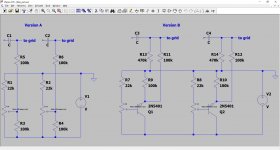
It is nevertheless a neat and effective amplifier, and importantly, it is highly evolutive: this is the plain vanilla version, but serious improvements are possible without too many complications; more on that later.

The main drawback of ultra-simple MOS-followers based amps is their output voltage swing heavily curtailed by the MOS threshold voltage, typically several volts under load.
Add the inevitable losses from the source resistors and the drivers and you are left with an output of Vrail minus 5 to 10V for each rail.
For high-power amps, the loss is relatively benign, but with 10 or 15V of total supply voltage, practically nothing is left to drive the load.

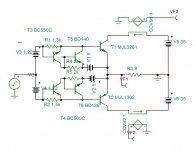
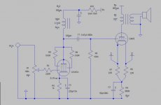
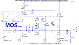
EZ-MOS solves the problem by bootstrapping for the positive rail and a "bias memory cap" for the negative one (or GND for a simple amplifier like this one).

The result is a 3-transistor + bias topology capable of swinging 28.5Vpp with a 31V supply: not bad for a simple follower-based amp.

One of the main drawback is the inverting configuration, but even renowned designers like Renardson use it.

attachment.php


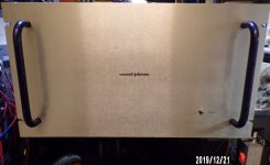
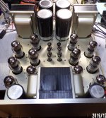
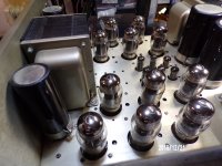
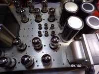
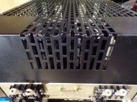
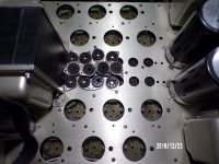
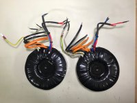
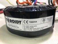
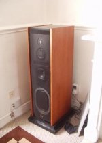
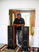
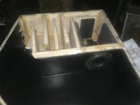
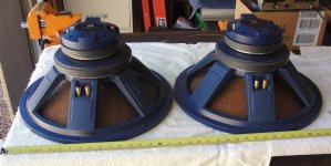
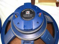
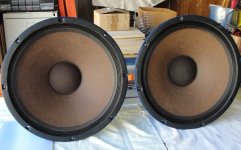
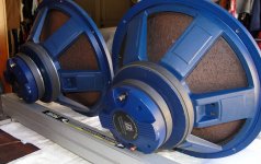
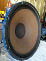
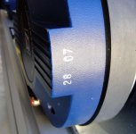
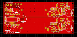
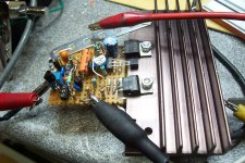
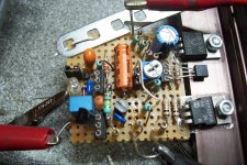
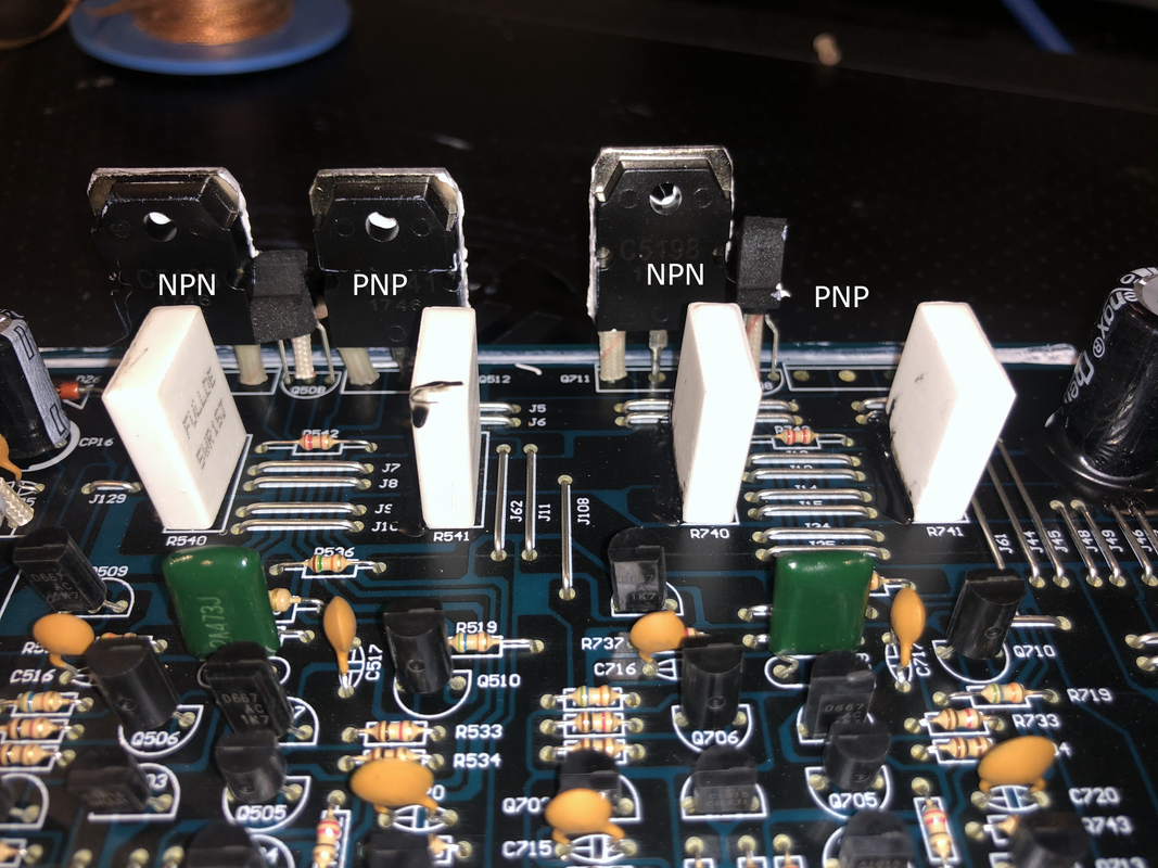
Here are pics of my prototype:

attachment.php


attachment.php


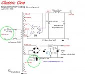
The low-power MOSfets can be almost any low-power type like 2N7000, and the OP can be any approximate complementary vertical pair.


My prototype is wired for a ~30V supply and is capable of putting out ~12W @ 8Ω, but other voltages and load impedances are possible just by scaling R13.

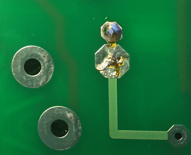
You can probably notice that the board is heavily populated compared to the schematic: that's because of the evolutive aspect.
The prototype includes all the options, but here the jumpers are in the "plain vanilla" position.
More will follow

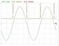
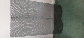
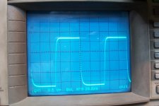
Here is the 10kHz, large signal squarewave response:

attachment.php


Not blindingly fast for this version obviously, but clean and sufficient for audio purposes, at least in principle.
The simulated THD is a shade over 0.5%; in the same conditions, the measured THD is a shade under 0.5%, thus very close, which is normal for "high" THD levels.

Attachments

  • EZmos0.png
    EZmos0.png
    23.9 KB · Views: 3,913
  • EZmos1.jpg
    EZmos1.jpg
    428.2 KB · Views: 3,625
  • EZmos2.jpg
    EZmos2.jpg
    434.4 KB · Views: 3,638
  • EZmos3.jpg
    EZmos3.jpg
    292.5 KB · Views: 3,791
  • EZmos.asc
    EZmos.asc
    5.5 KB · Views: 150

Markaudio 10m3 build

Following on form the thread below:

https://www.diyaudio.com/forums/full-range/354691-surprised-tangband-w3-fr-future.html

I ordered a set of the markaudio drivers and built up a set of cabs based largely around this design:

Mark Audio Alpair 10.3 Compact Bass Reflex Speaker Build | Mister Wireless

My own version has the same volume, similar dimensions (give or take 1cm based on MDF I already had cut), offset placement of drivers and a 50mm port tuned to ~45Hz.

Built up and speakers mounted, no finish applied yet and no internal damping materials.

I'm using them with a velodyne microvee sub and its ~100Hz internal xover to roll the bass off of the 10m3s.

How do they sound? Not too shabby.

There are comments that the driver has pronounced energy in the 5-7kHz range and some people use a simple LRC notch to attenuate this. Certainly, vocals can be overly sibilant and, to my ears, they get a bit fatiguing when turned up.

Measurement suggests that this is not so much a bump at 5-7kHz as it is cone break up causing exaggerated energy around this frequency range (you see a comb like series of peaks and troughs between 5kHz and 7kHz). I tried an active filter with a 0.7Q notch @ ~6kHz and this does reduce sibilance but also reduces desirable content in this frequency range. I'm hoping that a bit of internal damping material will help here and reduce the need for the notch filter.

Nothing like throwing additional complexity at a problem though so I looped in my minidsp DDRC24 and ran the Dirac Live 2.0 room correction software. This did an incredible job of smoothing out the high mids without sacrificing detail. It can still get a bit fatiguing when cranked up but, as I say, maybe internal damping material and a bit more burn in will help.

To really balance them out though I needed to give a wee bit of boost above 12kHz and a bit of baffle step compensation from ~200Hz down.

With miniDSP I have to say they are now fairly incredible. I was lucky enough to have mdf, ports and terminals left over from an old build so only needed to buy the drivers (£110 on eBay). For the cash they are an absolute steal.

My previous speakers are a set of ATC SCM11s which I'd previously thought to be untouchable. However, the vocals coming out of these wee FR drivers surpass the ATCs easily. All told, If I had to choose one set of speakers (and I might), I think the Markaudios might have it.

Surprised and delighted by the results.

Should I find time this week, I'll add some internal damping material and see what effect that has. Will report back.

Cheers,

iep

Repairing diaphragm on 15" Driver?

Hi All.

Came across this 15" Phonic Woofer marked "341-15058-610-0 15" 6Ω 225W".

I'm not familiar with Phonic speakers, and don't know whether this driver is for PA, or hifi?

There's a tear on the paper diaphragm.

Is this repairable?

How would I go about re gluing it?

Is this driver worth repurposing?

If it can be successfully repaired, I was thinking of using it in a simple DIY Subwoofer build.

I would mostly use it in a 2.1 hifi system, or as part of a sound surround set up.

Alternatively, is there a market for the driver itself?

cheers

Cliff

Attachments

  • Phonic woofer 1.jpg
    Phonic woofer 1.jpg
    622.2 KB · Views: 152
  • Phonic woofer 2.jpg
    Phonic woofer 2.jpg
    401.8 KB · Views: 141
  • Phonic woofer 3.jpg
    Phonic woofer 3.jpg
    544.6 KB · Views: 136
  • Phonic woofer 6.jpg
    Phonic woofer 6.jpg
    542.1 KB · Views: 127
  • Phonic woofer 7.jpg
    Phonic woofer 7.jpg
    433.8 KB · Views: 129
  • Phonic woofer 4.jpg
    Phonic woofer 4.jpg
    457.6 KB · Views: 81

DIY Spotify / Chromecast player

I am currently looking for a new streaming solution but I can’t seem to find one that is able to satisfy what seems to be simple requirements:
1. Gapless playback from Spotify connect and Tidal.
2. Supports Chromecast or other multi room playback, does not need to be gapless.
3. Lets me use my Spotify playlists.
4. Digital output I2S, SPDif or Toslink for external DAC.
5. Doesn’t require a software engineering degree to be set up.

Basically I want to build my own Naim Uniti Atom. I have looked at solutions like Up2stream and various R pi solutions, but none of them seem to support my own Spotify playlists or gapless playback.

Have I missed anything, or is there another way to integrate these streaming services to a DIY setup, that is not just a USB or Bluetooth player?
Projects by fanatics, for fanatics
Get answers and advice for everyone wanting to learn the art of audio.
Join the Community
507,772
Members
7,887,947
Messages

Filter

Forum Statistics

Threads
406,207
Messages
7,887,947
Members
507,772
Latest member
Hypertone