Hello again, I 've recently acquired a power transformer in order to feed a Linkwitz-Riley crossover and/or solid state preamp. Both can work great at +-15VAC. The device works, but I can't understand how it does it, as you will soon see.
So here's my power chain:
1) LED power supply, input 240VAC, output 24VDC
2) DC Voltage regulator with which I can decrease or even increase DC voltage
3) Mysterious power transformer 24VDC input, +-15VDC output and ALSO an intermediate dual AC output (that's the mystery part)
4) L-R crossover board (or discrete solid state preamp)
Now, the power requirements of the L-R board should be very low, about 2-3VA. The manufacturer states that it works within a range of dual 14VAC to dual 19VAC. Now to number 3), the mysterious device.
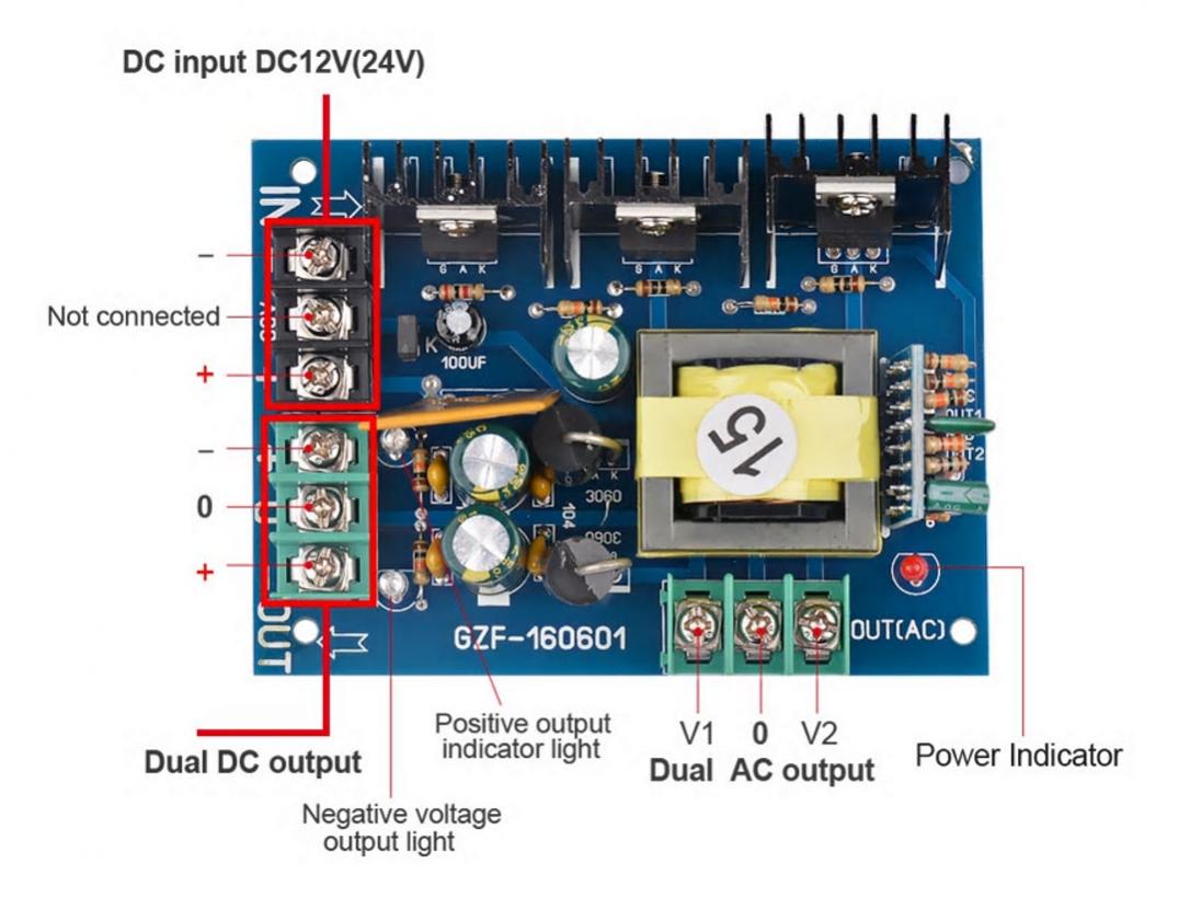
The device's stated purpose is to turn 24VDC to +-15VDC. However, I got it for its intermediate output, which is marked as dual AC. Only recently after inquiring with the manufacturer I realized this must be some not very supported output, and the only reason for this intermediate dual AC conversion is to create the +-15VDC output.
However, powering the LR board (~2-3VA) with this output does work. It can also turn on my pre which has a bit higher power demands(~10VA).
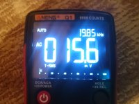
I'm certain most of you have recognized the board's design, I shall now be a bit more revealing. If I feed the device with 24VDC, this is what I get with my recently acquired True RMS multimeter at the dual AC output.

Yes, the reading is correct, it's a miniscule 15mV but with frequency of a whopping 20KHz! The device works ok because the dual DC output is pretty much spot on at +-15VDC.
Can you help me figure out what this board's principles of function are? I mean roughly how it is designed and how it works. Then I can see if and how I can utilize the intermediate dual AC output for powering stuff (safely). I'm pretty sure things flow from top left to top right to bottom right to bottom left. I suspect the tiny width voltage is used to feed the two caps near the +-VDC output, but can I use it elsewhere? Thanks for any insights/help.
So here's my power chain:
1) LED power supply, input 240VAC, output 24VDC
2) DC Voltage regulator with which I can decrease or even increase DC voltage
3) Mysterious power transformer 24VDC input, +-15VDC output and ALSO an intermediate dual AC output (that's the mystery part)
4) L-R crossover board (or discrete solid state preamp)
Now, the power requirements of the L-R board should be very low, about 2-3VA. The manufacturer states that it works within a range of dual 14VAC to dual 19VAC. Now to number 3), the mysterious device.
The device's stated purpose is to turn 24VDC to +-15VDC. However, I got it for its intermediate output, which is marked as dual AC. Only recently after inquiring with the manufacturer I realized this must be some not very supported output, and the only reason for this intermediate dual AC conversion is to create the +-15VDC output.
However, powering the LR board (~2-3VA) with this output does work. It can also turn on my pre which has a bit higher power demands(~10VA).
I'm certain most of you have recognized the board's design, I shall now be a bit more revealing. If I feed the device with 24VDC, this is what I get with my recently acquired True RMS multimeter at the dual AC output.
Yes, the reading is correct, it's a miniscule 15mV but with frequency of a whopping 20KHz! The device works ok because the dual DC output is pretty much spot on at +-15VDC.
Can you help me figure out what this board's principles of function are? I mean roughly how it is designed and how it works. Then I can see if and how I can utilize the intermediate dual AC output for powering stuff (safely). I'm pretty sure things flow from top left to top right to bottom right to bottom left. I suspect the tiny width voltage is used to feed the two caps near the +-VDC output, but can I use it elsewhere? Thanks for any insights/help.
Attachments

Last edited:
It's a switch mode power supply or "SMP". A quick Google will see you right.
Why do you want to use the AC output though? It will be rectified and smoothed to provide the DC output.
Both my devices require dual AC input. The L-R crossover states it will work within +-14VAC to +-19VAC and my preamplifier states +-12VAC to +-15VAC. So I need +-15VAC. The device of course provides +-15VDC (for 24VDC input) plus its intermediate high frequency output which I can't figure out. Reading a tiny bit about SMP (thanks for the identification) I suspect the high frequency is for efficiency reasons. I wonder if I can somehow utilize the intermediate output correctly to achieve +-15VAC. With my regulator I can tinker with the power supply's input from 8VDC to say 26-27VDC max.
Last edited:
You can feed them AC or DC. They'll also have a bridge rectifier and a smoothing capacitor. You'll have (marginally) less ripple by feeding them DC from your SMPS board versus the AC feed.
Also note that if they require +-15VAC that's probably more like +-21VDC as they'll be expecting a sine wave with 15V rms and peak around 21V
Also note that if they require +-15VAC that's probably more like +-21VDC as they'll be expecting a sine wave with 15V rms and peak around 21V
Last edited:
You can feed them AC or DC. They'll also have a bridge rectifier and a smoothing capacitor. You'll have (marginally) less ripple by feeding them DC from your SMPS board versus the AC feed.
Also note that if they require +-15VAC that's probably more like +-21VDC as they'll be expecting a sine wave with 15V rms and peak around 21V
Thank you sir for the idea. At the thought of feeding them DC, at first I was distraught because I can't push my power supply much past 24VDC input, which would be needed. But then I realized I already have a nifty DC-DC regulator.
")
I can verify there's a bridge rectifier clearly visible on the L-R crossover, not so clear where it is on the preamplifier board though:
Why do they build them for dual AC anyway? I'm sure there's reasons, but DC seems more straightforward to me.
Attachments
Thank you sir for the idea. At the thought of feeding them DC, at first I was distraught because I can't push my power supply much past 24VDC input, which would be needed. But then I realized I already have a nifty DC-DC regulator.
Whoops, I forgot the dual part. :-(

The 4 diodes form a bridge rectifier View attachment 804320
Indeed. So, I bit the bullet and pushed DC in to 26.75VDC. The transformer is apparently still alive and gives me an output of +-16.97VDC, precisely selected. The preamp lights up given its specs mention a minimum of +-12VAC.
Oddly(?) enough, when connected, the voltage drops slightly to +-16.30VDC.
Attachments
So, all is well and good, but what about the mysterious dual AC output? What is it exactly? Is it usable?
What I think I know is:
a) It is very high frequency, most probably 20KHz
b) Amplitude is unknown, for sure it is not what the multimeter registers (a few mV)
c) Waveform shape most certainly not sinusoidal, but square or triangular form.
So how do we make use of such an output? Initially I was thinking about comparing its effects on some system, to the effects of a traditional transformer with known parameters on the same system, to see how much work it can do. But I couldn't think of a setup I could use.
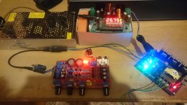
However: By having ubergeeknz pointing at the bridge rectifier, I had my "My lord, I have a cunning plan" moment. The plan is feeding the preamp with +-14VDC ("+-12VAC") then check DC voltage at the stabilizing capacitor, post rectification. The device is working within its parameters, so the DC voltage measured there is a valid target you can also obtain by other means. Like, using the dual AC output of the SPS with unknown parameters and tweak the SPS DC input with the regulator until getting the very same voltage on the capacitor. So there's the setup to compare things with. Solid plan eh?
Long story short: I played at dual 12VAC levels, powering a line selector and a preamp which can both work at that voltage. +-14VDC on the preamp input translated to 26.57VDC at the stabilizing capacitor. 14VDC on the input of the line selector (not dual, I used one side of the SPS) translated to 12.56VDC at the stabilizing capacitor.
Using the dual AC output, I ended up setting the regulator to 20.63VDC for the SPS input. In contrast, I needed about 23VDC when using the DC output. AC used more power, the regulator reports a power draw of 5.29W vs just 2.46W when using the DC output. There's some strange phenomena and observations I made but these are perhaps for another post.
I think the dual AC output will help me achieve +-15VAC levels while staying within specs (24VDC input) of the SPS. I will use the DC output briefly (off-spec, over 24VDC) for "calibration" measuring of the stabilizing capacitor voltage, then use the AC output with an input that's hopefully around 24VDC and not much higher.
What I think I know is:
a) It is very high frequency, most probably 20KHz
b) Amplitude is unknown, for sure it is not what the multimeter registers (a few mV)
c) Waveform shape most certainly not sinusoidal, but square or triangular form.
So how do we make use of such an output? Initially I was thinking about comparing its effects on some system, to the effects of a traditional transformer with known parameters on the same system, to see how much work it can do. But I couldn't think of a setup I could use.
However: By having ubergeeknz pointing at the bridge rectifier, I had my "My lord, I have a cunning plan" moment. The plan is feeding the preamp with +-14VDC ("+-12VAC") then check DC voltage at the stabilizing capacitor, post rectification. The device is working within its parameters, so the DC voltage measured there is a valid target you can also obtain by other means. Like, using the dual AC output of the SPS with unknown parameters and tweak the SPS DC input with the regulator until getting the very same voltage on the capacitor. So there's the setup to compare things with. Solid plan eh?
Long story short: I played at dual 12VAC levels, powering a line selector and a preamp which can both work at that voltage. +-14VDC on the preamp input translated to 26.57VDC at the stabilizing capacitor. 14VDC on the input of the line selector (not dual, I used one side of the SPS) translated to 12.56VDC at the stabilizing capacitor.
Using the dual AC output, I ended up setting the regulator to 20.63VDC for the SPS input. In contrast, I needed about 23VDC when using the DC output. AC used more power, the regulator reports a power draw of 5.29W vs just 2.46W when using the DC output. There's some strange phenomena and observations I made but these are perhaps for another post.
I think the dual AC output will help me achieve +-15VAC levels while staying within specs (24VDC input) of the SPS. I will use the DC output briefly (off-spec, over 24VDC) for "calibration" measuring of the stabilizing capacitor voltage, then use the AC output with an input that's hopefully around 24VDC and not much higher.
Last edited:
I need to correct my numbers since 14 is obviously not 12*sqrt(2)
line selector - DC
27.78VDC at regulator output
16.97VDC at line selector input
15.52VDC at post rectification cap
preamp - DC
27.78VDC at regulator output
+-17.01VDC at preamp input
32.55VDC at post rectification cap
So I need 27.78VDC as SPS input to use its DC output. A bit out of spec I think, esp. for long term use.
With the AC output, I figured things worked pretty well close to 24V so I removed the regulator altogether.
line selector - AC
24.00VDC LED power supply
15.13VDC at post rectification cap
preamp - AC
24.00VDC LED power supply
34.27VDC at post rectification cap
So the line selector is a little under spec but still works properly. The preamp responds much more to voltage increase but is safe since we are at "+-12VAC" levels and it can go up to +-15VAC.
My numeric error earlier means I've already done all the experimenting my SPS can handle. To try +-15VAC max value (over 20VDC) I would need an input that fries the SPS. Thankfully I have a good old fashioned +-15VAC 15VA toroidal transformer on its way to my doorstep. I can use it to measure post rectification capacitor voltage, see if I can reach it with the SPS. It will also be an interesting comparison in terms of noise. I think using the AC output introduces some hummm.
End of rant and thanks for your patience.
Given you are driving the bridge rectifier in the pre-amp with high frequency AC you may need to change the rectifiers to something faster than conventional silicon rectifiers, possibly UF prefixed parts would be fast enough.
Thanks for your input! How will this improve things? Also, can you perhaps enlighten me as to why my true-RMS multimeter suddenly becomes untrue-RMS when encountering this hf AC voltage? It reports around 10-13mV. Note: the front panel is marked "9999 counts" at its top right, perhaps this has something to do with it.
Last edited:
Hi yannikab,
You've done a good job describing these puzzles With two additional chunks of info it actually makes a good bit of sense.
'Square wave vs sine wave', and 'power input flexibility to reduce returns'.
The transformer secondary is providing a 20kHz square wave, with probably very fast edges. The formulae using sqrt(2) for the relationship between RMS and Pk-to-pk won't be any help. The multimeter is having trouble due to the frequency -- True RMS conversion is bandwidth-limited. The owner's manual will say how much, but handheld instruments historically are in the 8 - 12kHz range. (Your results may vary.)
As long as you think of 'sine wave' when you think of 'AC', it'll be confusing.
I'd like to go a step beyond kevinkr's excellent recommendation and encourage you to skip the AC input plan altogether! It's very likely a business/marketing decision that saves them a percentage of blown-up boards being returned. (Yes, I'm cynical .. sorry) You already have back-to-back switching regulators (SMPS's) that are giving exactly what your boards REALLY want: Clean +/- DC at about 15V! It'll surely work just like that, but you may want to consider adding a couple ferrite beads and ceramic capacitors in each line. Then after verifying polarity, skip past the bridge rectifiers on each board (leaving them intact, since there is no harm but a tiny bit of leakage), and connect straight to the rails. That way you'll have the full benefit of the regulators, and no unnecessary parts getting unnecessarily warm by discarding voltage unnecessarily.
If you insist on applying a 20kHz square-wave AC to an audio board, faster diodes might be only the beginning of 'things that need improvement'. And there's really no reason at all to do so, except convenience.
If you're worried about getting the polarity correct (very important), there's an easy and foolproof way to do it: With the board just like it came, and your new 15VA transformer connected to the AC terminals, put your meter's black probe on signal ground and measure the bridge outputs, observing polarity, then mark each with a felt tip. Victory!

Best Regards,
Rick
You've done a good job describing these puzzles
With two additional chunks of info it actually makes a good bit of sense.'Square wave vs sine wave', and 'power input flexibility to reduce returns'.
The transformer secondary is providing a 20kHz square wave, with probably very fast edges. The formulae using sqrt(2) for the relationship between RMS and Pk-to-pk won't be any help. The multimeter is having trouble due to the frequency -- True RMS conversion is bandwidth-limited. The owner's manual will say how much, but handheld instruments historically are in the 8 - 12kHz range. (Your results may vary.)
As long as you think of 'sine wave' when you think of 'AC', it'll be confusing.
I'd like to go a step beyond kevinkr's excellent recommendation and encourage you to skip the AC input plan altogether! It's very likely a business/marketing decision that saves them a percentage of blown-up boards being returned. (Yes, I'm cynical ..
sorry) You already have back-to-back switching regulators (SMPS's) that are giving exactly what your boards REALLY want: Clean +/- DC at about 15V! It'll surely work just like that, but you may want to consider adding a couple ferrite beads and ceramic capacitors in each line. Then after verifying polarity, skip past the bridge rectifiers on each board (leaving them intact, since there is no harm but a tiny bit of leakage), and connect straight to the rails. That way you'll have the full benefit of the regulators, and no unnecessary parts getting unnecessarily warm by discarding voltage unnecessarily.If you insist on applying a 20kHz square-wave AC to an audio board, faster diodes might be only the beginning of 'things that need improvement'. And there's really no reason at all to do so, except convenience.
If you're worried about getting the polarity correct (very important), there's an easy and foolproof way to do it: With the board just like it came, and your new 15VA transformer connected to the AC terminals, put your meter's black probe on signal ground and measure the bridge outputs, observing polarity, then mark each with a felt tip. Victory!
Best Regards,
Rick
Last edited:
Merry Christmas Rick, and thanks for your excellent response.
I 'll just point out one thing besides your recommendation on simply going DC.
My observation is that while at 27.78VDC at regulator output (to determine "target" voltage at post rectification cap) I got 12*sqrt(2) VDC on both the line selector and preamp inputs, when I switched to 24VDC at regulator output and AC output of SMPS, the devices responded differently. The preamp picked up more voltage (post "target") at the post-rectification cap, while the line selector did not pick up quite as much and was a bit pre "target". This clearly shows the differences in the rectification stage, the diodes themselves. The diodes are even visibly different, preamp has small "packaged" diodes (which I didn't even realize were diodes at first). The line selector has smaller components that look like monochromatic resistors.
Bypassing the rectification is quite compelling. I presume your mentioning of the importance of correct polarity and also marketing/burned boards are related. I think this is something I can easily pull off (and it would totally be my "style" so to speak, cut the middleman), my only question is about what additional components I may need between the SMPS and DC input of the device, always talking about +-15VDC and devices that run at about 10-12VA max.
I presume that even the incoming 15VA toroidal will ideally need some intermediate components, most likely capacitors, as I see them almost every time I see a transformer powering some device. And a most newbie question: What purpose do they serve and how does one roughly size them?
Thanks and Best Wishes,
Yanni
I 'll just point out one thing besides your recommendation on simply going DC.
If you insist on applying a 20kHz square-wave AC to an audio board, faster diodes might be only the beginning of 'things that need improvement'. And there's really no reason at all to do so, except convenience.
My observation is that while at 27.78VDC at regulator output (to determine "target" voltage at post rectification cap) I got 12*sqrt(2) VDC on both the line selector and preamp inputs, when I switched to 24VDC at regulator output and AC output of SMPS, the devices responded differently. The preamp picked up more voltage (post "target") at the post-rectification cap, while the line selector did not pick up quite as much and was a bit pre "target". This clearly shows the differences in the rectification stage, the diodes themselves. The diodes are even visibly different, preamp has small "packaged" diodes (which I didn't even realize were diodes at first). The line selector has smaller components that look like monochromatic resistors.
Bypassing the rectification is quite compelling. I presume your mentioning of the importance of correct polarity and also marketing/burned boards are related.
I think this is something I can easily pull off (and it would totally be my "style" so to speak, cut the middleman), my only question is about what additional components I may need between the SMPS and DC input of the device, always talking about +-15VDC and devices that run at about 10-12VA max.I presume that even the incoming 15VA toroidal will ideally need some intermediate components, most likely capacitors, as I see them almost every time I see a transformer powering some device. And a most newbie question: What purpose do they serve and how does one roughly size them?
Thanks and Best Wishes,
Yanni
Definitely should be using ultra-fast soft-recovery diodes or schottky diodes for high frequency rectification. However with schottky diodes you have to be careful about leakage current thermal runaway if the voltage is significant - they should be heatsinked if in doubt.
If you only want to rectify at signal levels (not power / high current), then signal diodes like the 1N4148 are fine (note that these are 75V rated only). 1N4148's are very fast.
If you only want to rectify at signal levels (not power / high current), then signal diodes like the 1N4148 are fine (note that these are 75V rated only). 1N4148's are very fast.
Definitely should be using ultra-fast soft-recovery diodes or schottky diodes for high frequency rectification. However with schottky diodes you have to be careful about leakage current thermal runaway if the voltage is significant - they should be heatsinked if in doubt.
If you only want to rectify at signal levels (not power / high current), then signal diodes like the 1N4148 are fine (note that these are 75V rated only). 1N4148's are very fast.
Hello Mark, thanks for your input! I think I 'll be going down the DC path which Rick suggested. It's only a matter of doing it right. And of course all this discussion is not in vain as I have a better understanding of what I'm dealing with (hf AC), why I can't measure it with my multimeter, and how it should be properly handled (fast diodes).
Merry Christmas to you as well, Yanni
Working from bottom to top of your next to last post .. Happily, the transformer should plug right in -- providing it is either center-tapped or dual secondary. The capacitors are already provided, but the good question about sizing them should reasonably wait -- its kind of messy and there are a range of views, many of which I'm not qualified to explain.
The rectifiers on the 24V to +/-15V supply look like they might be 5 or 8A Schottky's. In any case you can bet they are better suited to 20kHz rectification than the general purpose units (on the preamp and L-R crossover boards) designed for 50/60Hz service. Their common cathode and common anode nodes are a good place to connect the power. And by using the DC outputs you can completely avoid the 'antenna wiring' effect of 20kHz square waves going around to each board.
Diodes come in many packages, but it has no effect on the forward voltage drop. Schottky's are different; most others will drop 0.65 - 0.85V or so with 70 - 100mA of forward current.
The exact rail voltages on each board are rarely critical. There are plenty of high performance audio circuits that use +/-12, +/-15V, even single rails of 9, 18, 24V or others. Especially those that are opamp-based -- as I'm guessing your L-R board is -- are practically indifferent to supplies, as long as they're stable, high enough to avoid signal clipping, and don't exceed the opamp's maximum rating.
This is a fine project, and you're well on your way.
Cheers,
Rick
Merry Christmas to you as well, Yanni
Working from bottom to top of your next to last post .. Happily, the transformer should plug right in -- providing it is either center-tapped or dual secondary. The capacitors are already provided, but the good question about sizing them should reasonably wait -- its kind of messy and there are a range of views, many of which I'm not qualified to explain.
The rectifiers on the 24V to +/-15V supply look like they might be 5 or 8A Schottky's. In any case you can bet they are better suited to 20kHz rectification than the general purpose units (on the preamp and L-R crossover boards) designed for 50/60Hz service. Their common cathode and common anode nodes are a good place to connect the power. And by using the DC outputs you can completely avoid the 'antenna wiring' effect of 20kHz square waves going around to each board.
Diodes come in many packages, but it has no effect on the forward voltage drop. Schottky's are different; most others will drop 0.65 - 0.85V or so with 70 - 100mA of forward current.
The exact rail voltages on each board are rarely critical. There are plenty of high performance audio circuits that use +/-12, +/-15V, even single rails of 9, 18, 24V or others. Especially those that are opamp-based -- as I'm guessing your L-R board is -- are practically indifferent to supplies, as long as they're stable, high enough to avoid signal clipping, and don't exceed the opamp's maximum rating.
This is a fine project, and you're well on your way.
Cheers,
Rick
View attachment 804659
View attachment 804660
Thanks for taking the time to mark these pics Rick, much appreciated. Your investigative skills work well, if you notice under the bottom red box, the DC output is marked with the correct polarity. Also thanks for pointing out that what I thought were packaged diodes weren't after all. As for further experimentation, I will follow up when the +-15VAC "standard" transformer arrives. Thanks all!
Thankfully I have a good old fashioned +-15VAC 15VA toroidal transformer on its way to my doorstep. I can use it to measure post rectification capacitor voltage, see if I can reach it with the SPS. It will also be an interesting comparison in terms of noise. I think using the AC output introduces some hummm.
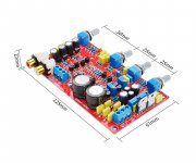
Here's yours truly again. After a bit of an adventure involving a missing shipment package, the toroidal transformer finally arrived. Specs:
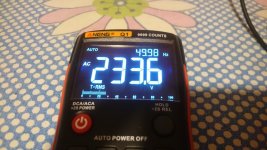
As far as I can tell it is a dual primary, dual secondary (not center tapped) transformer. Each side of its PCB has 4 pins for connection, and the middle ones are not connected. I have connected the primary coils in series and fed it my country's voltage which is as follows:
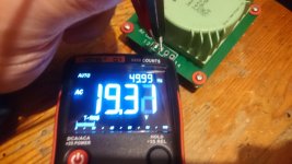
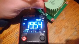
What is puzzling however is the output. Here's what I get on each secondary coil:
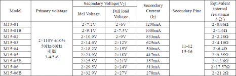
Now this seems not quite right to me. This is a dual 15VAC transformer, when fed 220V. I would assume that it yields (235/220)*15 = 16VAC per coil when fed 235VAC. Could it be problematic, off spec, overwound, whatever? I was expecting something like a dual 16VAC "reference" transformer and this seems to be offering much more, in fact more than what my devices can handle spec-wise. Your thoughts?
Attachments
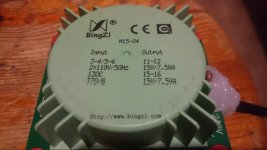
...meanwhile, guys and gals, yours truly had the cunning idea of looking up the spec sheet for the device. And yours truly discovered there's this concept of idle voltage vs. full load voltage. 
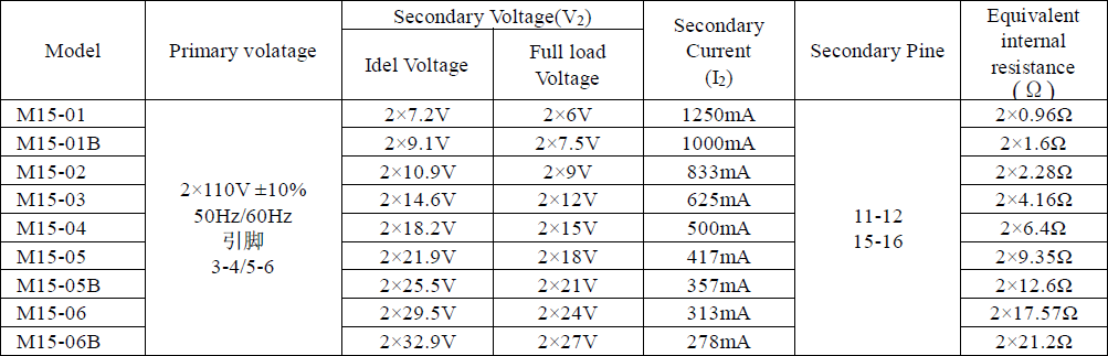
Turns out that (233.6/220)*18.2 = 19.325VAC. The device delivers an average of 19.425VAC which is pretty much spot on (+0.5%).
Turns out that (233.6/220)*18.2 = 19.325VAC. The device delivers an average of 19.425VAC which is pretty much spot on (+0.5%).
Attachments
Last edited:
- Status
- This old topic is closed. If you want to reopen this topic, contact a moderator using the "Report Post" button.
- Home
- Amplifiers
- Power Supplies
- A most mysterious (to me) power transformer