Recapping questions from a newbie

Hi diyAudio,
I have a Musical Fidelity A3.2cr pre amp and amplifier separates. They are about 17 years old (2003 manufacture). They have never been serviced and I am currently not experiencing any issues (that I am aware of). They get a lot of use ~3 hours listening a day, and I leave them on all the time. They are class A/B and biased about 3watts in A and warm to the touch at idle.

A. is there any point in doing anything before there is a problem? No caps are bulging or leaking.

B. If recapping is suggested, how difficult is it for someone with limited electronics/soldiering experience. I own a Weller soldiering station for the occasional fixing of things

C. If recapping is suggested and I have someone else do it, can anyone recommend a shop in the Chicago area? I am in the NW suburbs but also can deliver downtown.

From my searching, I do not believe there are schematics available for the Musical Fidelity amplifiers. I only know of one shop in the UK that does rehabs of these units and the owner is a former Musical Fidelity technician that opened his own shop. I don't really want to ship 40lbs of amplifier to the UK and back.

Thanks for any suggestions.
Andy

Briangt rev 2 LM3875 build advice

I built two rev 1 LM3875 amps back in the day and was gifted a pair of rev 2 boards that I never built. I have most of the parts necessary to build these save for the transformer and I need an extra amp so I'm looking at building these.

Looking at chipamp.com on the Wayback Machine I came across the rev 3 / carlosfm unregulated PSU. I've come across a few variations of the schematic. Is this rev 3 PSU still the way to go?

My rev 1 builds are using 330VA 25+25V transformers. I don't currently have particularly difficult speakers to drive but would it make sense to use a lower voltage transformer for this build? With Avel Lindberg through parts-express, it seems my only other option would be 250VA 18+18V. Searching Digikey gives basically the same result.

Thanks.

Lifespan of Black Gate caps ?

I built a Millett Hybrid Max headphone amp about a decade ago and used a bunch of Black Gate caps. It's been a great amp but I'm ready to move on to other things...I just built the Whammy, and may also build the NuTube headphone amp.

Is there any reason not to desolder the Black Gates from my old amp and use them in new projects? They still function fine, apparently, and regardless of the hype I think they sound great. I know electrolytics can dry up, but I also have a 40-year-old Yamaha receiver that still works great, so I take that with a grain of salt.

Measuring phono stage RIAA accuracy with a computer

I've been modifying a cheap commercial 3-transistor phono stage as a little hobby project to see how good it can sound. I've been messing with the RIAA filter lately, but this is a bit hit or miss without having an accurate way of measuring the response. I tried generating a RIAA equalized frequency sweep using Audacity and then playing it back through the phono stage making a recording and doing a spectrum analysis on the resulting recording. The results were not good, they weren't precise enough to really be able to use them for finetuning the response. The best they could do was confirm what my ears were telling me - that there was a slight rise happening from 10kHz onwards and that there was some bass rolloff. But that treble rise for example could've been +0.2dB or +0.7dB for all I could gather from the spectral analysis.

So I'm looking for a way to get more accurate recordings and analysis - basically I'd like to feed the phono stage something (pink noise? frequency sweep?), record that and analyze it in a way that gives me a nice, precise line from 20-20kHz where I can see it's down 0.1dB at 200Hz and up 0.2dB at 2kHz etc.

I'd think this should be relative easy to accomplish using the right tools, but I'm not sure what those might be, so I'm asking if anyone has been through this road (with Linux software hopefully) and to share their experience and what tools they used. Thanks!

Rotel RC 995

Having trouble with this unit and need some help ( schematic is available )

All voltage are present the unit is in mint condition and i trace the problem around TC 9173P and TC 9174P problem is that these seem to be very obsolete plus that it seems that i cannot get any datasheet for them in order to start checking a few things around .


Any ideas ???

Kind Regards
Sakis

Mark Audio drivers? Questions I hope am not repeating a post?

Good evening and I hope all of you are staying safe and healthy. I have a few questions that I hope have not been answered already? I am looking to build full range speaker for T.V. duties and low back round music. So here are the drivers am looking at?

1. Alpair 7 and 7MS and 7p and pluvia seven HD 4's and the sevens PHD 4's.

2. Alpair 11MS and pluvia 11's.

I know there is a lot between these drivers as I could guess not all drivers sound the same. I did have a pair of 3 inch blue cone driver years ago. It sound awesome in the mid-range but the highs sounded like it was missing sparkle on top and the bass well it's a 3 inch driver. I have never heard anything new from Mark Audio in years. I am looking at all of these drivers I listed. I need help with the sound and characteristics of his driver's like the M11 means Mono suspension. Does it really make a difference in sound to the other newer metal cones used by mark audio? Also are they bright sounding like other metal cones I have in the past sound like tin cans? Well please let me know? Am kinda excited to start a new project for my bed room and the T.V. Also how are the new paper drivers sound? Thanks Jeff

300VA 2 x 18v trafo - which Class A?

After ditching the idea of using a my higher voltage transformer for a Class A build, a friend of mine has kindly given me a toroidal 300VA 18+18VAC transformer which he no longer needs.

I was planning on starting by building a low noise regulated power supply while sourcing the transistors and other bits for the amp.

Can anyone suggest some options for a Class A design which will match a transformer of this size and output? Primary focus is on the best quality sound, but also preferably something reasonable simple and without really hard to source matched transistors.

Hirage Le Monstre usually calls for 12-14V I think. Would this be too high?

JLH?

Hiraga Le Classe A 20W?

One of the Pass Labs designs?

College Student Having Dilemma

I am currently an electronics engineering student and doing a project at the moment. My proposed project is this, "Cry Detection System". To detect if a sound is a cry or not, I have already used the neural network in Matlab. Now, the problem is to be able to process the real time recording of a baby (i.e. if the baby is sleeping, I will place a microphone connected to a laptop and leave it there). My solution for this is to divide the input sound recorded by the microphone every 10 seconds so my neural network can process it, but I have no idea how to do it. Any suggestions on how to do this? What software can I use? Or have you guys thought any other way on how to process the input sound? Thanks in advance.

Passive radiator + ports - possible?

Hi guys

I am contemplating building a subs using both ports and a passive radiator. The box will be big (circa 480 liter nett.) and my idea is to use dual length ports tuned to both 25Hz and 20Hz. But, since the sub will be capable of it, I want to add a PR, tuned low, for extension below 20Hz. Ports of any decent size for frequencies below 20Hz gets very long. My thinking is that with the ports in the box the PR will be lossy, which is OK, but there will be some additional extension. I might also experiment putting some wool in the ports to see what the effect will be on the PR. My question is just- will it work? My thinking is that this will be like multi-length ports, albeit more lossy in the very low frequencies than ports would be. Any thoughts?

Deon

TMC, Miller, Cherry, Mine compared

I formed a simple amplifier to test these compensations. Most of the distortion measured is noise.Output 30Vp
posted order TMC Miller Cherry and mine bellow.


attachment.php


Hayk

Attachments

  • SIMPLE NON SWITCH AMPTMC.JPG
    SIMPLE NON SWITCH AMPTMC.JPG
    358.5 KB · Views: 186
  • SIMPLE NON SWITCH AMPMILLER.JPG
    SIMPLE NON SWITCH AMPMILLER.JPG
    343.1 KB · Views: 185
  • SIMPLE NON SWITCH AMPCHERRY.JPG
    SIMPLE NON SWITCH AMPCHERRY.JPG
    347.4 KB · Views: 187
  • SIMPLE NON SWITCH AMP.JPG
    SIMPLE NON SWITCH AMP.JPG
    367.4 KB · Views: 1,138

Struggling with EQ on a portable speaker

So I built this boombox a little while ago and I've been trying to implement a minidsp to get it to sound better. The thing is, whenever I try to eq it I make it sound like crap. For whatever reason, I haven't had this problem with the speakers inside my house, but for this one, since it is portable, I've been taking it outside to measure and eq it. I sit it on a desk and push it to the edge so the desk doesn't reflect, and make sure it's far away from anything outside that can interfere with my measurements. I use a umik 1 mic with a proper stand now and set it up four feet or so behind the right channel of the speaker. I have the mic aimed right at the tweeter where my ear would be while I'm listening. (This is a typical woofer + tweeter arrangement so the tweeter is on top just like a bookshelf speaker) I have the left channel disconnected so it doesn't interfere with the measurements. I can eq it so that it reads within +- 2 db on a graph but it sounds awful, it doesn't sound faithful at all. When I do a frequency sweep manually and listen for how flat the speaker is it's very obvious to me that it's far from flat even though that's what the graph shows. My handheld spl meter confirms this. I'm not sure what exactly I'm doing wrong, I've done this several times and I'm on the verge of giving up and not using any eq at all but I hate leaving performance on the table, especially when I already have the minidsp. I will add that it might be a factor that my enclosures for the drivers are a little strange, the enclosure for the tweeter is separated from the woofer. I'm not sure how much of a difference it makes. So what am I doing wrong? Is there a book somewhere telling me how to properly do something like this?

Passive woofer crossover peaking issues

Hi All,

With a previous speaker project finished and out of the way now, it's time to start on the next project - a large floor standing three way system which has been on the boil conceptually for many years which I now have all the drivers for.

While I wait for a chance to start on building cabinet etc and get more detailed (in box) measurements, I've been spending a bit of time doing some preliminary crossover design experimentation and have run into a bit of a hurdle with the woofer crossover suffering from excessive peaking.

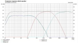
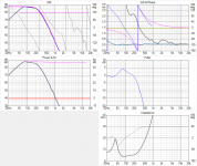
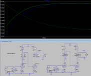
The Woofer is a Visaton W300S 8 ohm, (12") and the intention is to put it into a large bass reflex box of approx 110-120 litres tuned to 25Hz. The woofer will be close to the floor for optimal mid/upper bass performance. Here's a basic box sim in Vituixcad:

attachment.php


I'd describe this as an early gradual roll off response, which is 3dB down at about 35Hz and 6dB down at about 29Hz.

The original intention was to passively cross it over at 250Hz with a L/R 4th order accoustic roll off, but this is proving a real challenge due to the interaction of the woofer impedance.

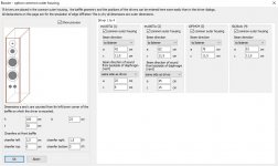
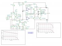
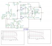
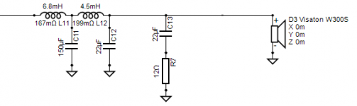
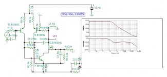
Here is the current circuit:

attachment.php


The issue I'm seeing is a huge 4dB peak in the filter response centered around 80Hz, along with a minimum input impedance of about 4 ohms centered slightly above this:

attachment.php


This is presumably a combination of the capacitive reactance of the woofer between 50-150Hz, and the low pass filter acting as a resonant impedance transformer - by causing the input impedance to go well below the woofers actual impedance (6.8 ohms DCR, about 8 ohms above resonance) it is effectively "boosting" the filters output 4dB above the input, and obviously this is undesirable.

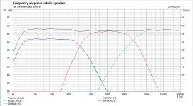
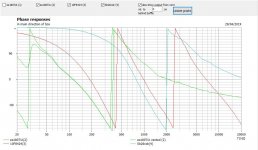
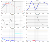
I was still able to manually tune the response of the filter to get a spot on 4th order L/R accoustic low pass filter response (theoretical target is the purple curve) including predicted baffle step loss, and also a flat summed resonse from about 80Hz up with good phase tracking to the midrange driver, however I'm still not happy about this situation for a number of reasons:

1) I don't like the impedance dipping down to 4 ohms in the bass. Yes a lot of speakers do this (although usually by being a 2 1/2 way or similar) but it's an unnecessary strain on the amplifier and also makes the impedance variation across the spectrum greater thus making the tonal balance of the speaker more sensitive to speaker cable resistance / amplifier output impedance variations, something I'd like to minimise.

2) While my midrange and tweeters are quite sensitive (95 / 96dB respectively) this artificial and unwanted voltage sensitivity boost in the upper bass region of the woofer doesn't leave me with much attenuator wiggle room for the mid/treble networks to get the tonal balance correct, especially when the near floor mounting of the woofer will give it about another 2dB of gain vs the high mounted midrange.

3) The artificial peak near 80Hz completely changes the low frequency roll off shape of the bass, changing it from an early gradual rolloff with a smooth gradual curve to a sharper more abrupt rolloff which is now 3dB down at 56Hz and 6dB down at 44Hz - a far cry from the un-modified driver response of 35Hz and 29Hz respectively. 🙁

So what can be done about it ? In a passive network, not a lot it seems, although I'm hoping someone has an idea I haven't thought of...

A few thoughts:

1) I could in theory add a series tuned trap to notch out the 42Hz impedance peak, however that is totally infeasible as the capacitor and coil values would be humoungous and expensive, with the resistor dissipating a huge amount of power.

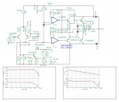
2) I could shunt the woofer with say 33 ohms to flatten the impedance curve out a bit near resonance. Despite adding a shunt the minimum input impedance actually increases to about 4.6 ohms due to the impedance transformation effect. This also avoids a capacitor and coil and does give some improvement, however the resistor still disspiates a lot of power at the frequencies where the woofer impedance is high, for relatively minimal gain in the response. (The peak is reduced by about 1dB)

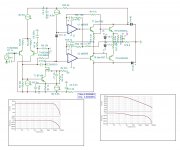
3) I could increase the crossover frequency a bit to get further away from the impedance peak - if I increase it from 250Hz to 300Hz the peak drops by 1dB or so but I'd hardly call that fixed, and I don't want to go any higher than 300Hz.

Other than that I'm out of ideas..... anyone else have any ? And no, "use an active crossover" isn't an option. 😛

It seems that this must be a fairly common problem with passive woofer crossovers ? On my last 2 way design the baffle step correction did interact a little bit with the woofer's impedance resulting in a broad 1.5dB peak around 100Hz, however this wasn't harmful in that design as the woofer was high mounted (being a 2 way) so would usually have a suppressed output in the upper bass due to room interactions anyway.

But in this design I deliberately want the woofer close to the floor for increased mid/upper bass response, so I don't want to add an additional big peak in the midbass due to the crossover itself, and I can't seem to tune out this 4dB peak without destroying the accoustic low pass function.

Attachments

  • Visaton enclosure Six-pack.png
    Visaton enclosure Six-pack.png
    66.4 KB · Views: 1,160
  • Visaton low pass schematic.png
    Visaton low pass schematic.png
    7.3 KB · Views: 1,335
  • Visaton Low pass Six-pack.png
    Visaton Low pass Six-pack.png
    76.4 KB · Views: 891

modi 3 -> amp: pop when powering off amp

I just replaced my preamp with a nanoDigi 2x8 so now my Modi 3 is connected directly to a vintage BrianGT LM3875 amp.

When I turn off the amp, I now get a brief pop/buzz sound out of my speakers. I've used this amp with several preamps and have never had this issue.

Yesterday, I swapped the Modi 3 with a Khadas Tone Board and the problem has gone away.

Other than the power off noise, the Modi 3 is normally quiet and well behaved.

Any ideas on why this occurring and how I can prevent it?

Gemini ES-15BLU

Hi all,

I got this above mentioned subject loudspeaker for repair.when I drive 100hz sine wave only upper part of it shows in the output. But when I heat the area near drivers I am getting good sinewave output. I checked all the transistors and resistors and everything seems good. I also checked if vias is trouble and I did not see any broken trace. What could be the reason and how to solve this. Thank you.

Is there someone in Australia that can build a Red Baron/Tube-i-zator DAC? Brisbane?

Unsure if this is the right place to ask but I have had a few PCB's lying around for years now. Looking to finally pull the trigger and get a build under way but I my electronic knowledge is 0. I can solder, that is all.


Is there some in Australia, preferably Brisbane that can assist with the build. I would of course pay you for your time.


I have the PSU PCBs, Red Baron PCB and Tube-i-zator PCB. I don't have the Salas shunt PCB's but I believe they are easily available.

Amp Project for my 88db ProAcs

Hey all,

Its been a while since I've posted here... Life, marriage, moves, dogs, kids, jobs, kid with cancer, covid.... Anyhow, all is well bow and I'm interested in getting my 2 channel system back up and running.

I have ProAc D15s at 88db. I built a 12b4a linestage that was feeding an AR VT100 MKIIs. Sold the VT100 and was using a PP EL34 kit for a while but that is now gone. I have a 10 year old breadboard of a 6sn7>300B>845 but I don't want to work on that now as the voltage scared me back then, and well, its been a while since I've used the solder iron.

What I would like to build is a solid, clean amp to power the ProACs. 35 Watts is decent but for big transitions, having more headroom would be ideal.

As I mentioned its been a while since I've been here. My old brain would tell me 6550 in PPP? What are other options that would suit my needs? What's changed in the past 8 years?

I listen to classic rock, piano, bluegrass, jazz etc.

All help and guidance is appreciated.

Many Thanks,

Bryan

Transistor KTC3911S-GR replacement

Hello to all,

I have a question: may I replace:
KTC3911S-GR
KTC3911S datasheet

with
2SC2713-BLLF
2SC2713-BL,LF Toshiba | Mouser

Honestly, I don't know too much about transistors.
I checked datasheets and it looks OK, but I am not so sure, so I have to ask.
KTC3911S-GR is SMD version, I will appreciate also standard version through hole.

Thank you for reading and have a nice evening/day 🙂

Kebschull 150/

I'm in the process of servicing this (massive) amp - but I sorely miss a schematic/service manual. - Does anyboby know if it's "out there" - or even better: Does anybody have a copy they could share?

Of course, I have searched the net, but hardly anything turns up, so I'd be glad to get any information what-so-ever.

Attachments

  • kraftklub_150103.jpg
    kraftklub_150103.jpg
    340.6 KB · Views: 188
  • Kebschull 150.jpg
    Kebschull 150.jpg
    25.4 KB · Views: 205

Mundorf Mcap Supreme outer foil?

I’m having a hard time determining the outer foil side of Mundorf 0,47 µF Mcap SUPREME Classic capacitors.

The trick with the oscilloscope (10 mV scale) doesn’t show any difference between connections and the 50 Hz. hum is hardly noticeable when touching the capacitor’s body.

I’m not sure what to do now. Leave it undetermined and just pick a side?

Regards, Gerrit

Attachments

  • C09C27CA-DD84-4C4B-960E-91CD2E88ECAD.jpeg
    C09C27CA-DD84-4C4B-960E-91CD2E88ECAD.jpeg
    44.5 KB · Views: 198

Old elector buffer for headphones

so i found this obscure buffer while back https://www.diyaudio.com/forums/analog-line-level/26846-simple-discrete-unity-gain-buffer-post316511.html
And have been using it where ever i can with great success. In comparison i find it to sound even better than a jlh buffer and in fact its the best sounding low part count buffer i have tried.

Now id like to scale it up to drive headphones much like the way the dao buffer is used and would like to know how id do that.

Simply tweak the resistor values and use medium power bjts on heatsink? Hmm

Searching: synergy horn drawings for 2x10” and 1”

Hello,

I’m searching for drawings or advices about how to calculate for a synergy horn fitting two 10” fane sovereign 10-300 and one 1” Sica 120.44/640 Poly. The enclosure should be 660mm wide, it’s the only demand I’ve got since it must fit my subs underneath. Otherwise I’m totally open for suggestions regarding shape or technique.

Anyone got something fun in the drawers? 🙂

Modifying TransformerModelsRev4.xls models ?

Hi Folks,

i have been using Robert McLean's excellent "TransformerModels Rev4.xls" utility from this site to generate output transformer models for LTspice.

Does anybody know how i can modify a model generated (Ham1645) from Mr McLean's data set to provide two separate secondaries ?

i'm trying to simulate the Drake output transformer found in the TVA-1 valve amp from the late '70's/early '80's which has a 0-4-8 ohm speaker secondary and a 0-16 ohm secondary connected oddly to provide negative feedback.

Please see attached circuit diagram.

Thank you for reading this post,

xx.

Attachments

  • TVA1Schaltung.jpg
    TVA1Schaltung.jpg
    196.1 KB · Views: 107

1 bit dac made from 74HC373 D-Flipflops?

Hi,

I just came across the service manual for the a family of Kenwood CD-Changers

kenwood_1060cd_1070cd_d-r350_dp-r6090_7090_sm.pdf

which is available for download at electrotanya.

It seems they have a chip to compute the bitstream and then two 74HC373 per channel, directly followed by the opamps.

What are the advantages of using external logic gates for output switches and downsides? Why would they use D-flipflops? One would assume it is the preceding chip's business to get the timing right, so if they wanted to get the switches off the substrate, a HC04 or HCU04 should have done the job.

Attachments

  • dpr6090_d-flipflop.PNG
    dpr6090_d-flipflop.PNG
    176.2 KB · Views: 415

Why doesn't my Pre Amp increase the volume?

I am in a DIY project of upgrading a 1967 BeoLab 700K receiver.Beomaster 700

I want to add a streaming module connected to the Line-IN (Tape) of the receiver. That way I can listen to the tuner or switch to the Tape IN for streaming music.

For the streaming module I use the Acrylic Up2Stream Mini v2. https://cdn.shopify.com/s/files/1/0072/6899/1049/files/Up2Stream_Mini_v2.pdf

When the Up2Stream is connected to the Tape IN of the receiver, the volume is lower then the volume when listening to the tuner. So when switching back to the tuner, the volume is very loud.
Obviously, the audio-out signal of the Up2Stream module needs some pre-amplification. I was advised to use the AD828 pre amp board for that. AD828 Datasheet and Product Info | Analog Devices

So I connected the Audio-out of the Up2Stream board, to the Audio-IN of the AD8282 Pre Amp board. Unfortunately, after testing I found out that the signal does not get amplified. At least not noticeable. When switching between Tape IN for streaming and tuner, the volume on the tuner is still much louder than on the Tape IN.

Question?
What is the right solution to solve this? Is the AD828 the wrong Pre Amp to use? Did I miss something? I am looking for advice, please let me know your suggestions.

PS.
For powering the Up2Stream Mini and the Pre Amp, I have added an isolated AC/DC converter. Isolated to prevent ground loop. So both boards are powered from one AC/DC converter. 3Pcs HLK-PM01 AC-DC 220V To 5V Mini Power Supply Module Intelligent Household Sw - US$10.87

FYI
I have added a PDF of the setup of my connections between the modules. See the attached PDF.

Attachments

FS: Maida Regulated Power Supply

I have a spare Neurochrome 21st Century Maida Regulator surplus to my requirements;

kfT0O5m.jpg


Product information is available here;

21st Century Maida Regulator: A modern B+ voltage regulator – Neurochrome

It's fully assembled and tested, configured for 300VDC @ 50mA but easily changed by swapping out two resistors. I'll include an additional PCB for the rectifier and filter cap required upstream of the maida reg.

£40 plus shipping at cost plus paypal fee.

Power amps and capacitative loads

I have a Velleman K4040 clone power amp which gets very upset with capacitive loads. I first noticed it years ago when I tried some Litz speaker cables, and it oscillated. Just recently I bought a pair of Quad 2805s and tried it with them. I though I had destroyed the speakers! It made such cracking noises that I leapt up and switched it off as quickly as I could. The speakers are OK, but it reminded me of the earlier Litz episode. A little Ming Da EL84 amp is fine, and of course my Parasound A21 is too.
I have just read something about putting a 1k resistor across the output terminals to tame this; is that a reasonable method, or is there a better way? Or even a different value?
Any advice welcomed, as I built this amp over 25 years ago (one of my first forays into cloning) and it would be nice be able to use it again.

No bass sound

My NAD 3130 has developed a fault where there is no bass, (extreme treble). My speakers are the Bose acoustimass 5 and only getting sound from the tweeters. I initially thought that I had speaker problems but found this not to be the case after trying a different amp. Anyone experienced this problem that can suggest the cause?
Thanks

Project Idea - comments please

Having lurked, asked stupid questions and been down a number of blind alleys (and been re-directed by those with much more knowledge than I will ever have, thanks), I think I have converged on a Project Idea.

So, I will try and explain it (only modeled so far) and I would be grateful of any comments that either confirm this has a good chance of working or where I need to sort stuff out.

1) Enclosure
Tallish, slim floorstander - external - 100h x 23w x 30d cm - 25mm ply with window bracing and 28mm butchers block baffle = 40l internal volume, will be lined, mid will be in separate enclosure approx 1 liter (probably fibreglass moulded around coke bottle, stuffed and sealed to baffle).

2) Architecture
Simple TMWW - active system with Minidsp crossover, anechoic correction (notches) and room EQ. I have two Rotel RMB1066 which can supply 150w in 8 ohm x 2 and 60w into 8 ohms x 2 each - one for each speaker . Therefore Woofers need to be 8 ohm.

3) Driver Choice (UK location so limits some choices)
Woofer - Dayton ES180TiA-8 - modeled in 20l with 30Hz tuning for port (5cm diam x 15-20cm long, both ends flared) x2 (in same enclosure of 40l).
Mid - Scanspeak 10F8424 - modeled in 1l close, stuffed box

Tweeter - SB26CDC
Not the cheapest drivers but all get good comments for their transparency and dynamics and woofers and mid share a similar construction.

4) Modelling (graphs provided)

Carried out in Boxsim v2.0 (Active filters, all driver in phase, all 4th order crossovers (2 x lowpass 2nd order)) and using Dayton's provide FRD/ZMA plus traced for the mid/tweeter - using manufacturers TS parameters. Initial parameters input then used the optimiser to refine.

All models are with zero offset/gain - this combination seems to work very well straight out of the box.

A) Low/traditional crossover - approx - 270Hz and 2800Hz

Woofer - Lowpass 2nd order x2 - 450Hz/0.57 + 266Hz/0.76 plus two parametric notches - 65Hz/3.75/1.25dB and 45Hz/3/-1.25dB
Mid - Highpass 2nd order x2 - 460Hz/0.89 + 306Hz/0.69 and Lowpass 2nd order x2 - 2050Hz/0.57 + 3150Hz/1.09 plus delay auto calc'd.
Tweeter - Highpass 2nd order x2 -1935Hz/0.49 + 2115Hz/0.45 plus delay auto calc'd.

This produced a nice flat frequency profile with just 2 parametric notch filters (to sort out bass end) and no gain leveling. However I think the low crossover is pushing the small 10f so modeled a higher crossover -

B) Higher Mid Crossover - approx - 550Hz and 3100Hz

Woofer - Lowpass 2nd order x2 - 610Hz/0.5 + 510Hz/0.7 plus two parametric notches - 65z/3.75/1.25dB and 45Hz/3/-1.25dB
Mid - Highpass 2nd order x2 - 570Hz/0.95 + 530Hz/0.7 and Lowpass 2nd order x2 - 2600Hz/0.75 + 3500Hz/0.75 plus delay auto calc'd.
Tweeter - Highpass 2nd order x2 -2780Hz/0.7 + 3550Hz/0.65 plus delay auto calc'd. Also added a parametric notch filter at 5100Hz/2/-2db.

This seems to model slightly better. at 88sB +/-1dB from 33Hz to 20kHz and F3 at about 29Hz

Options - I did look at the Anarchy 708 for woofers but these are out of stock and by the time you add shipping and tax for 4 they are close to the Daytons in price. For mids I modeled the Satori MR13P and MW13P, the 10F4424 and the Morel EM1308 but the 10F8424 modeled the best. For tweeter I looked at and modeled the 29RDC, Satori TW29R(N) and the 21RDC and 26ADC but again the 26CDC seemed to do the best job.

So, I have attached the frequency plots for the two models and the phase plots plus the box model if anyone feels the need to replicate and check it out.

But from my amateur/inexperienced standpoint this looks like a good combination for a transparent/dynamic, smallish floor stander that is pretty flat from 30Hz to 20kHz and need very little (if none) gain leveling and only minor notches to wrinkle out the dips/peaks (three actually).

So, all comments/suggestions welcome as I am here to learn so there is no need to be polite/gentle, I do not take offense easily.

Attachments

  • ES180TiAx2 10F8424 26CDC Box.JPG
    ES180TiAx2 10F8424 26CDC Box.JPG
    79.6 KB · Views: 562
  • ES180TiAx2 10F8424 26CDC Freq low xover.JPG
    ES180TiAx2 10F8424 26CDC Freq low xover.JPG
    135.1 KB · Views: 561
  • ES180TiAx2 10F8424 26CDC Phase low xover.JPG
    ES180TiAx2 10F8424 26CDC Phase low xover.JPG
    122.7 KB · Views: 548
  • ES180TiAx2 10F8424 26CDC Freq Hi xover.JPG
    ES180TiAx2 10F8424 26CDC Freq Hi xover.JPG
    131.5 KB · Views: 552
  • ES180TiAx2 10F8424 26CDC Phase Hi xover.JPG
    ES180TiAx2 10F8424 26CDC Phase Hi xover.JPG
    123.3 KB · Views: 554

Charred resistor on speaker output

Hey there,

anyone got an idea how I managed to kill R43 (and the corresponding R143 in the other channel) without noticing? They're completely charred.

Alpha3_OS.png

I am currently replacing R43 and R143 with 1/4W metal film. Originally it was carbon film, but I don't have those available. Seems I need to replace R44 and R144 as well. They're right next to the other two on the board and seem to have taken some damage from the destructive failure of R43 and R143.

Would you replace the caps in series to R43 and R143 as well? Visually they don't appear damaged, but something must have killed off those Rs...

EDIT: Thought about it again. Those resistors can only dissipate significant power if there is a lot of HF energy on the output, i. e. HF oscillation of the output stage. But why?

Kind regards,
Andreas

HP 400AB voltmeter rehab

I picked up the rackmount version of this for a song, knowing that it powered up, but was otherwise "as-is". Received it yesterday, and sure enough, it powers up! But the meter pegs as soon as it warms up. The voltages from the manual are all significantly off. The only one that's correct is the DC heater supply that's only used for two of the tubes.

The other heaters should all be elevated by 107V regulated by an 0B2, but that's sitting at about 35V with a big 320us spike to 71V once per cycle - looks like the VR is trying, and failing, to ignite. Other voltages are similarly low, I assume because the rest of the circuit appears to be referenced to that voltage. So the 0B2 looks to be toast. PT is putting out exactly in spec.

Nothing looks burnt, nothing smoked or seemed overly warm, all the heaters lit up, etc. I suspect that the rest of the tubes are pretty tired too, so I'll at least retube the rest of the power supply.

Is anyone else familiar with this meter, and can you provide any advice?

Sony ta-2000f problem

Hi
I have measure up my amp after repair of power supply.
However the problem (flat amplifier) is to high voltage,
2sk43-1 q501 q601.the rank is right idss 2.

r502 is ok, the rail is 37v but when i mesaure the 2sk43 the drain voltage is around 21v(7.5v)

I changed the R503 value to 1315k and get 7.5v

Same problem with the other jfets q504 q604.

I'm little lost here any ide what is going on?
Do i miss something?

br Tommy

Attachments

  • ta-2000f.png
    ta-2000f.png
    224.1 KB · Views: 160
  • ta-2000fn.png
    ta-2000fn.png
    290.1 KB · Views: 147

Loud Buzz

I've been prototyping a headphone amp for the past several months and have gone through close to a dozen iterations at this point. I think I have settled on a design now, but am having some problems with buzzing. The power supply is just a bridge rectifier with a basic Pi-Filter arrangement. Two 100uF caps separated by an inductor or resistor. Earth ground tied to DC ground. If my scope ground is plugged in to the amp power supply ground then it's all good. Nice and quiet. As soon as I pull that scope ground off of the breadboard though I get a very loud hum/buzz. Where the scope ground is plugged in doesn't matter, and plugging in a direct link to earth ground does nothing. Any ideas what I'm doing wrong here? I'm at a bit of an impasse.

2 Pole (IP+VA) Stage

Lessons learned from preceding designed, I understood that it is unrealistic to seek distortions bellow 0.0001% at 10khz 30Vp, where noise dominates the measurements.
Instead of designing the IPS and VAS separately , Why not design them together . As my OS has a distortion 0.0013% for 30Vp 10khz , with hybrid version it showed that 30db NFB is sufficient. To have an overall gain of 25db, only 55db is necessary for the (IP+Va) stage to provide.
The circuit bellow has a distortion of 0.0005% , with mosfet inputs zvp3310 it is slightly lower, Jfets also can be tried out.


attachment.php


Hayk

Attachments

  • IPS+VAS.JPG
    IPS+VAS.JPG
    57.5 KB · Views: 273

I confess.

Many years ago I had a PA system that was the envy of all the land. Four 18" scoops with Eminence drivers shook the ground in all the kingdom. On top, banks of Piezo tweeters deafened with their shrill, harsh tones. But the thing that made me Lord of all that the land that I could see was the unrivalled efficiency and quality of my midrange section. The vocal power of Whitney Houston could be heard, crystal clear, from the next realm, and beyond.

I confess: shoved 8" full-range drivers as far as they would go down the throat of traffic cones.

There was no science involved.

Any published Bass Reflex setup for the ScanSpeak 10F/8424G00 ?

Hi,

I am looking for an already published design to BR load this little full range for a 3 db spl gain vs a sealed design to reach 98 db vs the 95 dB ax outputt.

The Bass Reflex would not hurt me as the Fl planned is around 750 hz and the driver Fs only 100 hz...

Sure I can sim it, but as BR are difficult to setup fine, if any reliable already I will apreciate it, please.

I plan a 9cm dia.round tube I can easily put the tube port at the back in front of the rear of the cone and setup the internal volume by solids wich play the role of brassing and standwaves breakup before the back load sees the port!


Many thanks

High frequency when IQaudIO DAC hat stops playing.

My IQaudIO DAC Pro emits a high frequency note when music stops. The DAC has been used without this issue since I installed Raspbian about 14 months ago.

Unfortunately, the Raspberry Pi 3B+ is very demanding on current, and I have to use an SMPS with all its unwelcome electrical filth.

The outputs from the DAC are taken from the RCA connectors which drive an LM3886 based stereo amplifier. The amplifier does NOT have automatic gain management.

I play music using a terminal using mpg123, mplayer and VLC or cvlc. I control volume using alsamixer. Pulseaudio and systemd were removed from the system. Alsamixer displays a long list of controls instead of single control.


Post Scriptum:
I will post an oscilloscope image of the irritating waveform as soon as the issue shows its ugly head.

DOGC-H. Studio SE del Dr. Borivoje Jagodic

hi I have seen here in other posts that there is talk of DOGC-H amplifiers by Dr. Borivoje Jagodic and I have printed the pcb but, if someone can help me x the psu or to the encumbrances of how many goes it must be a transformer power or in dual mono? I also read about studio SE. but I can not find the scheme x make the pcb and other info .. can you help me? thank you

Volume Surges Fender "The Twin" - transformer going?

Hello all -

I just finished replacing all the caps in my Fender red knob "The Twin". I also replaced a number of resistors in the power stages and across the output tubes. This corrected a number of problems (crackles, pops, hum) that I was having but not the main problem.

http://www.bnv-gz.de/~ooehmann/schematics/fender/The_Twin_Schematic.gif


The main problem is that the Amp sounds fine for about 10 minutes until it gets warmed up good and then the volume surges really loud. I can stop the surge by throwing the amp's Hi/Lo switch from whatever state it is in and then volume resets. After a short bit the volume surges again. Throw the Hi/Lo switch to the opposite setting and things quiet back down.

Here is what I have tried -
1. Have run the amp with 4 or 2 outputs tubes - just need to change the speaker impedance setting. Switched out various tubes in the pair. Does not cure the volume issue as it occurs regardless of tube combinations.
2. Remove all output tubes and install a pair of Yellow Jackets and EL84s. Volume issue still present.

I have also noticed that when setting the amp bias I have to turn the trim pot all the way to get .4 volts. Actually, I only get 3.5. I can balance the tubes no problem. I don't think the output tubes are the problem. I beginning to wonder about other things like a failing transformer, a semi-fried transistor or rectifier, or just a power diode going bad.

I am not an expert a repair but do know my way around a circuit board. Also, I only have a multimeter to trouble shoot with. Can anybody give some clues as to what might be the culprit?

Jerry

Best 1000$ bookshelf

So, I've been itching to build my second set of speakers for about a year now. My first build was a kit, lower end (200$) from Zalytron some years ago. I'm not yet ready to branch out on my own, so am going to be sticking to a existing design for this next one.

I have my building materials/tools already, and can afford 500-1000$ this time around for drivers and crossovers. I was looking at Paul Carmody's Carreras, but I only have about 2 feet behind the speakers to work with, and am worried the rear port won't have enough room to sing.

I have spent a lot of time researching, looking at different builds, but when so much moolah is on the line, I'm having a hard time making a final choice.

So I'd like recommendations for your favorite bookshelf speakers in this price range to help me make my choice. I'd love a build you've found where the vocals shine. Thanks so much!

211 driving 211 Amplifier

I am in the process of planning my next project. A project to dwarf all other projects.
211 driving a 211. I have been able to get an idea of transformers I need and have been able to find good operating points.

Has anyone run 211 tubes at low voltages? I find that running the driver 211 at high B+ and high bias causes rolls off. but low bias, low voltage raises f3 by almost 10dB.

The graphic provided shows two possibilities.
The lower bias/B+ lowers f3 by 10dB to almost 30Hz.
The right runs higher B+ and higher bias and f3 is 40Hz.


The PSU is going to be insane, going to use Rod Coleman filament Regulators and insane B+ supplies. Thing is gonna cost a ton to build but why not.

Attachments

  • 211 Driving 211 DHT amp.png
    211 Driving 211 DHT amp.png
    26.1 KB · Views: 1,069

Recommendation needed for small HiFi sub.

Hello folks!


I recently built a Class D amp. Spent some $$ on transformer and PS, sounds great. Decided to replace my old garage sale multi way cabs with a pair of Elac B6.2. They sound great. However, I'd like to feel some bass. Perhaps years of car audio have tuned my ears a certain way, but I want a bit more. In my car I run a single Jl 12W6v2 in a sealed box. I think I use 10% of its possible db, but I love how flat the frequency response is. Granted, it was a $500 sub before the box, I see that the current JL 12w6 series is like $800.

The problem is that I can't find a good, not too loud home sub for $200- $300. The JL "HiFi" powered sub is like $1200. There must be another way.

Amp - $300.
Full range Elac B6.2 $250
Well reviewed HiFi subs, $600???

I don't need a powered sub. In the spirit of DIY I want to add a sub out to my amp (which will require a discrete class D amp, perhaps 85W RMS MAX). It seems ludicrous to spend $600 to get a good sounding sub for a system that cost $600 total.

So, are there any options here? Searching for DIY subs I immediately get sucked into home cinema where everyone is talking about arrays of "18 subs running 1000w ea. blah blah.

I've found some popular flat packs, but again they are running like $350- $1000. Is there any reason I can't grab a used JL 10" or 12" car sub from eBay and build a box for it? Are there any good options for passive subs in my price range?

I found Chane Home Cinema, they will very soon be releasing some subs in the 200-300w range and seemingly they will be in my price range, but are they any good? Also, they are powered, so I'm paying for amplification I don't even want.

Any recommendations for a driver that has very even frequency response, fairly low power, that runs maybe $150?

Non-snake oil input coupling cap recommendation

I'm looking for input coupling caps for a headphone amp I'm building. The amp is discrete and the output is direct coupled. The input caps are 0.47uF.

I personally don't have an electronics background so can't reason why one design is better than the other, and for lack of better knowledge believe subjective opinions on whether boutique cap A is better than boutique cap B.

Reading other cap recommendation threads, subjective opinions about caps whether they are Mundorf, Jupiter, Jantzen, etc etc are quickly disregarded as snake-oil and request for measurements and numbers are requested as proof.

So my question here is directly to those who stick with the electronics theory, which brand / material type of film cap do you rely on if needed for input coupling?

Thanks

Feedback request.. 32W amplifier 14x32 student design

Good evening DIYaudio

I am a university student studying EE (years ago I studied ME). In the past year I have spent countless hours trying to complete a schematic for an amplifier that would work well for SE input and could power bookshelf, headphones, or possibly use as a fixed output preamp. Basically a versatile low power amplifier that could be biased into class A.

I give credit to others for the design, as there is quite a bit of others (some quite well known around here) fairly well published work principally making up the design. I do not take much credit for anything other than adapting existing topology to meet what I was hoping to achieve. I admit the parts count is a little bit high, but the simulation looks promising.

I am a complete novice and although I have a basic understanding of the functioning mechanisms of the amplifier I would greatly appreciate others with much more experience that have the time to look it over. I may have done things that won't work or have left out important parts. I know I am missing a zobel network on the output and I would like to add diode protection for the output FETs.

If it does seem to be reasonable to build, I have not much of a clue where to start with PCB design, so recommendation of any reference materials to read or design guidelines is greatly appreciated.

Attachments

Built ideas for existing drivers?

Hey there,

I finally retired my almost 30 year old transmission lines. I was young and inexperienced when I built them, so I no longer like their appearance or sound today. Replaced them with a commercial set of speakers recently.

But I think the drivers are still fine and I would hate to see them go to waste. So I have two Visaton W170S cone bass/midrange drivers and two Visaton DTW8.12NG fabric dome tweeters.

Maybe some small bookshelf speakers for the workshop area, kitchen or office might be interesting.

Anyone got a nice idea about those drivers?

Kind regards,
Andreas

Please help me troubleshoot sudden unexplained feedback

I’ve got a simple PA setup with a wireless lapel mic, a couple corded mics, and a pair of powered speakers. This morning while only the wireless lapel was in use (by me), there was suddenly loud feedback. It happened twice, with no warning and nobody touching the sound board, the mic not moving at all, much less moving to in front of a speaker, nor particularly loud, nor a change in the talker’s volume.

I’ve run sound systems like this for years, and it’s always been clear to me what caused feedback. This time it felt like a hardware bug to me. Like the mic suddenly switched from mic to line level or the board suddenly shorted the channel to full volume or something. I don’t have any idea how to really figure it out. Am I crazy to think it could be hardware? The equipment has been in use in this room in this configuration for weeks without a problem.

Does anybody have any suggestion for how to troubleshoot this? It only happened briefly twice in 45 minutes of talking, so I don’t even know how to try to test anything.

Thanks in advance, and if I’m asking in the wrong place (or even the wrong forum) could you please direct me to a better place? I’m not familiar with audio forums.

What is this resistor used for? (Schematic provided)

Here is the schematic of a 2-way crossover network. I have a doubt on it. Could anyone help to clarify me, please?

1. For the cone driver section, what is the order of the network? Is it 1st order with impedance equalization circuit or second order with modified slope?
2. What is the responsibility of R1?
3. Someone had told me that the duty of R1 is to modify the slope of 2nd order to be less than 12 dB/octave, was it right?
4. If R1 is definitely a modifier of slope, to be less than 12dB/octave, how to calculate the value?
5. Can R1 and C1 be switched positions to each other?

Thanks in advance

Attachments

  • E21140B3-EEC9-46BD-A920-5565686A71F1.jpeg
    E21140B3-EEC9-46BD-A920-5565686A71F1.jpeg
    127 KB · Views: 218

Power needs across audio spectrum in active setup

I've been doing some thinking regarding power amp needs towards assembling my 4-way active setup and I'd like to share it to get your feedback. Looking forward to learning!

Somewhere, maybe in Floyd Toole's book, I remember the reference to 350Hz being the midpoint in power needs for audio. Assuming all drivers have the same sensitivity. Allow me to approximate said midpoint to 320Hz to simplify the rest of my reasoning. So 50% of the power used in reproduction is needed for the first 4 octaves, and 50% for the other 6 octaves.

Let me assume power won't be an issue below 320Hz as I have dedicated subs plus 400W class-D driving dual 10" midbasses per side. My concern is mostly power for the midrange.

Big assumption: if the lower 4 octaves in the audio spectrum consume 50% of power, I´ll venture 40% of the spectrum consumes 50% of the power. Extrapolating: at the 40% point of the top 6 octaves is the midpoint in power consumption. In other words: the amount of power needed for 320 to about 2kHz is the same as from 2kHz to 20kHz. Assuming drivers with the same sensitivity. Would love to get feedback on this.

Let me assume the tweeter will have 104 dB sensitivity and will be xo at 2kHz. While the midrange will be 97 dB sensitivity, of course running from 320 to 2000Hz. Hence, assuming tweeter and midrange amps are the same brand/model, the midrange amp will be the limiting factor.

Let's further assume the amp is a 2A3 SET delivering up to 4W, but I want to design for up to 2W to keep distortion low.
One midrange driver will deliver 97dB SPL at 1 meter using 1 Watt, and 100dB at 1 meter using the 2W I want to use as limit. Let's also assume a benign impedance curve.
Adding the second midrange driver (the one on the other speaker) it adds 3dB, so both together will be playing at 103dB SPL driven by 2W and measured at 1 meter in open space.
The listening position is at 2.4 meters, so 103+20*log(1/2.4)= 95.4 dB SPL at the listening distance with 2W, in an open space.
Adding 4.5dB as an estimated room reinforcement, I arrive at 99.9dB from the midranges at 2W at the seating position. Call it 100dB SPL.

That was the midrange, which is the limiting factor. Assuming the tweeter can keep up since it has higher sensitivity and driven by the same amp, it would add another 3dB SPL, so midrange driven by 2W plus matching tweeter would be delivering 103dB SPL at the listening position.
Along the same lines, midbass and subs running below 320Hz are also keeping up, so adding another 3dB SPL.

So I could expect such a system to be good to play up to 106dB SPL at the listening position if I wanted to limit midrange amp power usage to 2W. Is all this correct?

106dB SPL would be RMS, right? How should I factor in dynamic range in the music?
I usually listen at 85dB SPL C-weight, sometimes like to turn it up to 90dB, and rarely go to 95dB. I understand ideally I should build 20dB headroom, so ideally 115dB and at a minimum 105dB. Should I consider the full 4W amp capability for transients, therefore adding another 3dB, so the system would be capable of 109dB SPL peaks? But at 4W the amp is probably distorting so maybe I should steer away from that even for transients?

Your feedback will help me understand how close to the limit I would be with this amp and driver combination. Maybe I should consider other drivers or setups (such as MTM, arrays), or another amp. Definitely want to design a matching combination of amp and midrange.

Thanks for the patience and looking forward to your feedback!

Which regulator for phono preamp?

I'm building a Pete Millett's LR Phono stage and need a +/- 15V source.

I've got an assembled AMB sigma22 and transformer from a different project but its fairly big and would increase costs since I'd likely use dual chassis to put the transformer and PSU separately from the Phono board.

I've recently discovered Jan's SuperRegulator, and SilentSwitcher, both could work fairly well.
I like that the SilentSwitcher is small and can fit in the same chassis as the LRP.
The SuperReg also looks like a relevant option that could also fit in same chassis with a "wall-wart" supplying the power.

Which would you choose and why?

req: Behringer ultracurve dsp8024 midi software

Hi.
Im looking for the software to remote control a behringer ultra curve dsp8024 eq.
When I turn it on it says v1.2

Im running windows xp.

I find a version of the software. It says v1. But when trying to setup the midi in out, the softwares closed.

It is not in behringer.com anymore.

May I have some help please?
Does anyone have the software?

Thank you.

Samsung's Convergence

Harman has made no secret that they're using a target curve for all of their loudspeakers, and they've hired a couple of the pioneers of this work.

Kevin Voecks came from Snell in the 90s and has been designing Revel's speakers to this standard.

Floyd Toole wrote the book on this and worked at Harman up until a few years back.

In a nutshell, all of their speakers are designed to achieve similar goals. To me, it's interesting to see that the brands are sloooooowly converging on designs that are very similar.

To me, the reason that this is interesting is that we should be able to reach a point where loudspeakers are SO GOOD, they will be as difficult to distinguish from one another as it is to differentiate two Class AB amplifiers.

jbl-4367.png


qfClfuO.png


z1YBSNY.png


At CES in 2017, I had the opportunity to hear these three speakers in a row. The JBL 4367 retails for $15,000. The Concerta F36 sells for $2000 online. The Revel Ultima sells for $22,000 per pair.

Hearing the F36 after the 4367, I was honestly stunned by how similar they sounded. The spectral balance was similar. The 4367 had ridiculously pinpoint imaging. The F36 had a more diffuse soundstage.

To me, this was particularly interesting: magazines like Stereophile promote this idea that "Speaker A" images better than "Speaker B", but listening to the 4367 back-to-back with the F36 made me realize that the F36 sounds *different* not necessarily *worse.*

I am on a bunch of Facebook audio forums, and I've noticed that a lot of people have become convinced that there's some kind of link between "soundstaging" and "expensive tweeters." And from what I've found, objectively and subjectively, expensive tweeters mostly just play louder. IE, I can make a $20 tweeter image really well with the right waveguide and the right enclosure.

That last part is HUGE, and it completely bums me out that people seem to ignore that part:

I've found that the enclosure shape makes a *tremendous* difference in imaging.

For instance, the Revel Ultima costs more than both speakers, and it's imaging was indisputably better than the F36. The Ultima and the F36 sounded similar, but the Ultima "disappears" better. And IMHO, that has more to do with the roundover on the baffle than the quality of the tweeter. IMHO, of course.

Arguably, the biggest advantage of the Ultima over the F36 is more headroom, more power handling, more dynamics. There's a strong correlation between power handling and bandwidth. For instance, there are full-range speakers that can cover 40hz to 20khz with a single driver. But they're lucky if they can hit 100dB. The Ultima is a four way, with big voice coils and careful attention to cooling.

OcdUguU.jpg


Here's the woofer from the $15,000 JBL 4367. Look at those heat sinks, look at that voice coil. This isn't a cheap woofer.

If any of you are at an audio show and you have this opportunity, I recommend it highly. I walked into the JBL room prepared to write a check for a set of 4367s, and after listening to the Revels I was re-evaluating why I listen to horn in the first place. (I'm still a horn guy, listening to Yamaha DXR 12 as I write this.)

I wrote about this phenomenon here.

And there's a monster thread over at AVS Forum where the Revel beat the JBL M2 Reference in a blind test.

Low or crackling sound in speakers

Good morning,

I've recently bought an Audio-Technica turntable (it should arrive next week) so I decided to retrieve my father's integrated amplifier. It's a Sony LBT-V701, about 20-25 years old, which apparently worked just fine the last time it was used. However, when I plug my smartphone or my Echo Dot into it, the sound that comes through the speakers is either low (when plugged into the CD inputs -there're no AUX input) or crackling (when plugged into the PHONO inputs). I'm using a 3.5 mini-jack and 2x RCA cable. I've tested it with two different pairs of speakers (both came with mini HiFi systems), that work perfectly well except with the amplifier.

I'm not precisely an expert in audio systems, just an amateur, so maybe I'm missing something here. Just to let you know: (1) the volume both in the phone and the amp was turned max; (2) the amp doesn't have a tape monitor switch.

Thank you in advance.

Alternatives to Dayton ND16-FA6

Hi all,

I am Interested in trying to add a tweeter to my JMLC 350Hz horn and make it semi coax.

Currently using a 1.5 inch exit JBL 2452SL (4 inch diaphragm compression driver)

The aim is to make it closer to CD.

Currently the pattern narrows in directivity as frequency increases considerably. I would like to hear what it sounds like with a wider top end.

Pattern narrows down to about 15 degrees at 10 khz (see chart in link below this paragraph)- however note my driver is 1.5 inch, and does not show the widening anomaly at high frequencies)

JMLC-350 – Horns by Auto-Tech

I can 3D print, so would make the necessery mount fit smoothly to the existing horn, perhaps in the middle of the throat, but not too far inside.

I'm sure someone has tried this before.

Is it a good idea?

Can small 5/8 or 3/4 Inch tweeters like the Dayton ND16-FA6 produce over 100db SPL if crossed over at 7 or 8 khz? High SPL is a reasonable priority as I love big classical dynamics!

Are there any better alternatives for a very small tweeter with high SPL and low distortion crossing at 7khz or so?

I would consider changing the horn for a CD one, but the only alternative spherical horn with a roundover on the mouth (needed for aesthetic reasons) is a tractrix. This is wider pattern, but not massively, so and they are not as good looking IMO anyway.

I would love a SEOS or OSWG, but they are not available in a spherical shape and 350hz pattern holding (as far as I know?)

The M2 horn is available, but is not free standing or aesthetically acceptable without mounting in a cabinet.

I propose placing the tweeter where the coin is in the image below, half way down the throat in a smooth 3D printed bullet enclosure.

Shared album - lance bartlett - Google Photos

Any suggestions/advice welcome!
Projects by fanatics, for fanatics
Get answers and advice for everyone wanting to learn the art of audio.
Join the Community
507,766
Members
7,887,494
Messages

Filter

Forum Statistics

Threads
406,178
Messages
7,887,494
Members
507,766
Latest member
Coreque