Hi Folks,
i have been using Robert McLean's excellent "TransformerModels Rev4.xls" utility from this site to generate output transformer models for LTspice.
Does anybody know how i can modify a model generated (Ham1645) from Mr McLean's data set to provide two separate secondaries ?
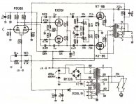
i'm trying to simulate the Drake output transformer found in the TVA-1 valve amp from the late '70's/early '80's which has a 0-4-8 ohm speaker secondary and a 0-16 ohm secondary connected oddly to provide negative feedback.
Please see attached circuit diagram.
Thank you for reading this post,
xx.
i have been using Robert McLean's excellent "TransformerModels Rev4.xls" utility from this site to generate output transformer models for LTspice.
Does anybody know how i can modify a model generated (Ham1645) from Mr McLean's data set to provide two separate secondaries ?
i'm trying to simulate the Drake output transformer found in the TVA-1 valve amp from the late '70's/early '80's which has a 0-4-8 ohm speaker secondary and a 0-16 ohm secondary connected oddly to provide negative feedback.
Please see attached circuit diagram.
Thank you for reading this post,
xx.
Attachments
Hi Folks,
Thank you for at least looking at this thread, if not actually answering.
Here's what i'm struggling to understand.
The .subckt model generated by TransformerModelsRev4.xls is this:
That's great, it works fine in LTSpice.
However, what i DON'T understand is to what the numbers 1 to 7 refer in the above .subckt definition ?
The inductance and resistance lines e.g.
LP1 1 Sg1 2.42968840701799 <= number 1 in this line
and
RS1 O16 5 0.1 <= number 5 in this line
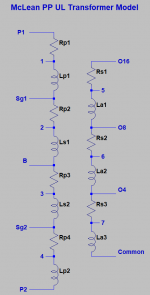
don't refer to terminal numbers - there are 9 terminals in this .subckt model (see attached drawing, a screen grab from the .xls spreadsheet).
Any ideas ?
Cheers,
Neil xx.

Thank you for at least looking at this thread, if not actually answering.
Here's what i'm struggling to understand.
The .subckt model generated by TransformerModelsRev4.xls is this:
.SUBCKT Ham1645 P1 Sg1 B Sg2 P2 O16 O8 O4 Com
* Push Pull transformer, with Ultralinear taps at 40%
* 5000 to 16 ohms, 3db 15 to 60000 hz
* speaker taps at 8 and 4 ohms
* Hammond 1645
*
* model generated by TransformerModels.xls 2020 Jun 27
*
LP1 1 Sg1 2.42968840701799
LS1 2 B 1.07986151423022
LS2 3 Sg2 1.07986151423022
LP2 4 P2 2.42968840701799
LA1 5 O8 0.00741645776380232
LA2 6 O4 0.00370822888190116
LA3 7 Com 0.02161314180004
KALL LP1 LS1 LS2 LP2 LA1 LA2 LA3 0.998434750532354
RP1 P1 1 30
RP2 Sg1 2 15
RP3 B 3 15
RP4 Sg2 4 30
RS1 O16 5 0.1
RS2 O8 6 0.1
RS3 O4 7 0.1
.ENDS Ham1645
*
That's great, it works fine in LTSpice.
However, what i DON'T understand is to what the numbers 1 to 7 refer in the above .subckt definition ?
The inductance and resistance lines e.g.
LP1 1 Sg1 2.42968840701799 <= number 1 in this line
and
RS1 O16 5 0.1 <= number 5 in this line
don't refer to terminal numbers - there are 9 terminals in this .subckt model (see attached drawing, a screen grab from the .xls spreadsheet).
Any ideas ?
Cheers,
Neil xx.
Last edited:
There are nine labeled nodes in the model, but the connections between each inductor and its modeled DC resistance are also nodes in the model. They haven't been given labels in Robert's diagram but they have implied labels based on an examination of the subcircuit. The attached image shows the implicit labels for these additional seven nodes.
As an example, note that in my diagram inductor Lp1 is connected between nodes 1 and Sg1. The subcircuit matches this. So the attached diagram is just a more complete version of the original, noting the node names between the inductors and their associated resistances, as well as the labels associated with the transformer leads themselves.
I hope this helps.