Crappy EL84 SE Amp

I was going through a box of random tubes, and I found a pair of EL84s. I decided to try building a single ended amp with them on a breadboard. For the OPT, I rewound a 120-12 volt line transformer until the primary read around 5.5K with an 8 Ohm load on the secondary. The amp does seem to have some ringing at high frequency, would this be why?


My power supply is just a dual 120 volt to dual 30 volt transformer run with the 30 volt windings in parallel, fed from a variac, and the 120s in series. This allows me to adjust the B+ to about 250 volts.

The gain stage is a 6C4 running at 180 volts of B+.


Surprisingly, this amp sounds pretty good in my opinion, aside from the HF ringing, which I need to look at into a dummy load with the scope tomorrow.


IMG_1237.JPEG

IMG_1238.JPEG

IMG_1239.JPEG

IMG_1240.JPEG

Hi from London, UK

Hi all,

Just signed up as I'm planning on embarking on my first DIY project and my searches for info keep landing me here. Clearly this is a useful place!

My plan is to give a tired old pair of active ATCs a new lease of home hifi life. They were DJ monitors in London's now defunct Movida nightclub, so they've worked hard. Now I plan to give them a comfortable retirement and some private healthcare.

They have the curved aluminium enclosure and drivers of the SCM20ASL mk1, and the amps of the T16. First job is to replace the amps with Hypex class D modules and create digital crossovers using filter plugins and Audio Hijack on my Mac. The signal from this will be sent to the speakers via a multichannel RME ADC/DAC.

Then next stage is to upgrade the Seas/ATC drivers and replace the front baffle.

When all that's tweaked, they'll get a cosmetic makeover.

It will be a long haul as I'm also trying to hold down a job and do up a house... but if I could ask some of you for help with digital crossover design, speaker measurements, and driver recommendations from time to time, I'd really appreciate it.

Will of course share pictures of progress - and looking forward to seeing yours!

All best,

James

Trouble finding Ceramic Capacitor for MS30 Crossover

Hi All, new member here hoping someone can help me with suggesting a replacement ceramic cap on my Mordaunt Short crossovers.

I bought the MS30's at a garage sale and found one of the drivers had very low bass reproduction. Testing the main terminals returned a value of about 200 ohms. The driver tested at about 6 ohms so process of elimination, I found one of the ceramic caps on the crossover was 194 ohms.

I have not been able to identify what type of ceramic cap it is, the capacitance or voltage. I tried measuring the capacitance of the good cap on the other crossover (out of circuit of course) but the value jumped around a lot so I took it to the local electronics store but they too were unable to help. The guy said the value of the cap 'might be' 450,000 pF from the markings but it could also be a manufacturers code.

I have attached photos of the crossover and a close up of the cap. If anyone has advice, I'd gladly hear it.

Attachments

  • 20200714_153011.jpg
    20200714_153011.jpg
    145.2 KB · Views: 129
  • 20200715_142551.jpg
    20200715_142551.jpg
    83.1 KB · Views: 141

Noobie trying to figure out this headphone volume knob

Hello,

I'm pretty much a noob when it comes to this stuff so I was hoping the experts here might be able to give me some guidance.

I purchased some gear from a radio station that went out of business. I'm going to be using their studio furniture in my home studio. This stuff has been in their storage for at least a decade so it's filthy and needs a little TLC, but I think I can give it a good home.

Built into the furniture is a lot of cool hardware, for example, these headphone jacks with volume knobs.

McowfpG.jpg


But these seem to have some kind of molex connection (is that perhaps balanced audio? Or one of the molexes is standard audio and the other is a passthrough to go to the next headphone jack? Taking random guesses here...) and I don't have a clue how to wire them to the standard headphone output from my mixing console. Seems to be a resistor between the volume knob and the headphone jack as well.

There are three of these jacks built into the table and I'd like to wire audio to all of them. Will definitely be getting an amplifier to handle that but I have no idea what I'm doing when it comes to the wiring.

Any idea where to start with these?

Recommendation for a Amp Module

Hi Folks

I'm looking to replace the modules I have in my amp with something a bit more powerful, ideally without changing the power supply / toroidals. I'm looking for suggestions for modules or kits that fit the bill. My DIY capability is fair, and fading with my eyesight 🙂

I have an Aspen LifeForce amp for a dozen years or so, and love the sound. It's been driving an old pair of Monitor Audios Silver 9i's. But I was offered a pair of B&W 802 Series 3's at a good price and couldn't resist. But the Life Force modules don't really have a enough power, and (designer) Hugh reckons they probably can't handle the dip to lower impedance on the B&Ws.

So this is the ask, and I know there's probably only a limited number of options that fit the bill.
- 150 W module
- Work with a -50V / + 50V PSU
- Get enough power from 330VA / 33V

If you have any ideas that would work please let me know. I've seen a Marantz (clone / inspired by??) module on eBay that sounds good on paper, but I'm nervous it would go bad and damage the speakers.

thanks
Norman

Audiotool

I went out and bought the IMM-6 mic and Audiotool app for android. I wanted to test my bass cab for frequency response in a simulated real world environment so I just set it up in the living room and set the mic/phone 3' away on axis with the center line of the cab. Horizontal and Vertical center line that is.

Playing bass live, you're on stage with two guitars and a drummer. There are reflective surfaces everywhere and lots of absorptive matter, so I figure the living room is kind of the best place. Kind of.

Here are two graphs, pink and white noise. I did not include a sweep.

What seems to be happening here?

Attachments

  • pink response 15.6.png
    pink response 15.6.png
    46.2 KB · Views: 152
  • White response 15.6.png
    White response 15.6.png
    46.2 KB · Views: 150

Arcam Diva AVR300 receiver-silver

I bought it as a fully functioning unit in very good condition. And, after initial power up hiccup it was working fine - for a day. Next day I couldn't power it up until I unplugged the amp for a few times from mains power. It dropped the DSP mode as well. I opened it up and there it was. A dreaded bulging 3300uF cap in the regulator circuit . You will need 12x 3A schottkys and a dozen of caps on the main boards replaced or just few main ones around regulators. Re-flowing the solder points on mother board won't hurt also. It will come with original box and manual but no remote- $80 .Now the sticky point which is shipping . Amp weights 46 lbs packed in 23"x 21"x 11" box so the shipping via Fedex will be expensive at over $50. I don't have fedex account so either you will send the shipping label or bear the retail shipping charge. The receiver is sounding very good when operating with more than decent RDS FM tuner. I will provide pictures if requested but its in a great cosmetic condition except loose speaker's terminals for center channel.
PS I should add that it was $2100 unit when new...

everything good comes in 2s

daydreaming about building an amp called "Double the Fun"

This power transformer with 2 of these 1641 {RK60} full wave rec tubes and the 7193 driver pushing the 815 output tube. I can't think of anything 2 related for the output trannies.

Attachments

  • IMG_20200712_113234676.jpg
    IMG_20200712_113234676.jpg
    87.4 KB · Views: 276
  • 1641_westinghouse.png
    1641_westinghouse.png
    135.7 KB · Views: 290
  • 7193.png
    7193.png
    201.2 KB · Views: 291
  • 815.jpg
    815.jpg
    18.7 KB · Views: 289

Free old woofers, pick up in Portland OR only

These are a pair of old Audio Concepts DV-12" woofers. In 2011 I posted a bunch of measurements of theses.

https://www.diyaudio.com/forums/subwoofers/190727-subwoofer-testing-orientation-ii.html

Note that the T-S parameters for the two drivers are different. The box one was in had "BAD" written on it when I received them. I don't know which one was bad. They both work.

Pick up in St. John's neighborhood of Portland OR only. PM me for a time to pick up.

-Byron

Attachments

  • WIN_20200722_16_40_05_Pro (2).jpg
    WIN_20200722_16_40_05_Pro (2).jpg
    98 KB · Views: 120

Linkwitz Pluto + MiniDSP + ClassD

I've built the Linkwitz Pluto, utilizing a MiniDSP and cheap ($50) 4x100 @ 4ohms Sure TK2050 Class D board. The result is outstanding, even with the board a little under powered with a 24V SMPS. My plan is to upgrade to a few high quality classdaudio boards in the near future, enclosed in a nice chassis with a toroidal transformer.

I made a YouTube video. My cheap pocket camera does not do the accoustics justice, but you get the idea....

/Mason

Active Boost Control, State Variable

Hi All,


I'm a bit stumped and have been for years on how to leverage active filters into actual tone shaping controls. Lots of articles explain how to make a "filter" but spend less time on how to blend various filters in tone shaping or equalizers, so it's never been 100% clear to me. After reviewing some EQ schematics I see a lot of mixing amps and examples of the filters being put into feedback loops. I want to make a high shelf control for a treble boost that can be controlled for frequency and gain. I don't need cut, I don't need steep filters, I'm concerned about noise. What I've come up with is attached. It uses a first order state variable that is explained on this page:

State Variable Filters

in figure 1A. I'm using this filter (Varying R5 for frequency) and mixing it into a summing amp via R8. As R8 drops the boost increases but the taper seems weird and I can't get the boost to 0 without making R8 infinite, so I added the attenuator of R4 and R9; R8 now sets max gain. That attenuator would be the "boost" potentiometer.

Is this a reasonable approach for what I'm trying to do?

Attachments

  • Screen Shot 2020-07-19 at 11.04.43 AM.png
    Screen Shot 2020-07-19 at 11.04.43 AM.png
    88.6 KB · Views: 129
  • Screen Shot 2020-07-19 at 11.04.53 AM.png
    Screen Shot 2020-07-19 at 11.04.53 AM.png
    77 KB · Views: 129

Creating my own bluetooth speaker

Hi,


I want to get into speaker building and want to start with a bluetooth speaker.


I selected these parts for now:
JB systems HT 100 bullet tweeter 300 watt kopen?
Celestion TF0510 ferrite woofer 5 inch 30W 8 ohm kopen?

Are these compatible and good?

I also need a bluetooth amplifier, does anyone have a suggestion? I'm located in Belgium if that matters.
For the power cable, how do I select one that won't fry the parts?

Is there anything else I need besides the wood / case?

powering lavalier microphone

hi , i have lavalier microphones that fits sennheiser wireless (trs 3,5mm plug) and need to power them up with phantom or maybe external bias voltage source. have an idea to use them with my binaural head but never figured out to power them with minimum noise. there are some diagrams but it seems not confidental. anyone give me idea about how to do it or show me a proper design

Power Amp advice needed, for my JBLs 4312 power thirsty...

Hi,
just finished my tube phono preamp after the well know scheme of Diego Nardi (Kos't, on sound practices), powered it up using my marantz 2235b as a power amp, and the speakers scream "let me fly, gimme power"...

So now, I was told about interesting projects by the Papa, but I can't find my North Star yet...
Well, what i need is preferably one chassis, big power (more or equal than 100W), class AB (yes, with the wattage involved I don't want to turn my living room in an oven)

Any hints?
Or should I go again back to tubes ?

Thank you!
Mike

40000uF 50v unregulated psu

I have 3 of these available.

One is unpopulated.
1 is populated unused (pictured)
1 is populated and used

The one in the pictures....i removed the wrapper from one of the Nover capacitors....just out of interest....it wasn't very interesting!

I used one of them with a 30V trafo giving about 40v dc for a 3255. It was powered up for months 24/7 no issues.

Can be used in dual polarity if required.

£13 for new unused
£10 for either the other 2
Postage in UK included...rest of the world on application.


Thanks

Attachments

  • 20200721_071847.jpg
    20200721_071847.jpg
    680.6 KB · Views: 232
  • 20200721_071854.jpg
    20200721_071854.jpg
    564.4 KB · Views: 232
  • 20200721_071901.jpg
    20200721_071901.jpg
    666.3 KB · Views: 229

Sale of special quality lamps

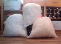
Cleaning of warehouses.
I sell a lot of different radio tubes
Basically produced by ussr.
Paypal \\ maybe Western Union
Order value + shipping costs +% paypal
Standard post dispatch from ukraine
For more information and photos, please send me your e-mail.
Please do not hesitate to make suggestions.
All lamps in a large number of 50-100-200 pieces
The minimum order is from $ 50
Maximum of 100 pieces in one order
ksz1111111@gmail.com
ksz11111111@mail.ru

2k2m direct tube 3$ pcs box 4$ pcs \\60pcs
6J9p frjazino Tubes 50`s gold grid 2$ pcs \\40pcs
6J9p-e frjazino LONG LIFE Tubes 50`s gold grid 3$ pcs \\
6J11P ( E280F ) frjazino reflector Tubes 50`s\60`s 3$ pcs
6P6S svetlana Tubes 50`s 10$ pcs \\ 50pcs
6V6GT svetlana Tubes 50`s\40`s 15$ pcs \\ 120pcs
6p14p \ 6p14p-k used 0,7$ pcs test ok \\ 350pcs
6p14p-ev LONG LIFE new 9$ pcs \\ 60 pcs
6p31s (6cm5\el36) black plate 3$ pcs Gray plate 2$ pcs new \\ >100pcs
2P1P direct tube new 1.2$ pcs \\ >80pcs
6P1P-Ev LONG LIFE new 1,5$ pcs \\ 250pcs
6P1P svetlana frjazino melz Tubes 50`s 1,5$$ pcs \\ 150pcs
6e6P-dru new gold pin SPECIAL QALITY LONG LIFE 7$ pcs \\60pcs
1521 ( spez 6e5p ) New Tubes 50`s SPECIAL QALITY 18$ PCS \\40pcs
1521-i( spez 6e5p-i ) new Tubes 50`s SPECIAL QALITY 18$ PCS \\ 40pcs
6S2P ( EC98 / 6J4 ) Triode Tube new 0.5$ pcs \\ >60pcs
6N2P (FF 6.3V-12AX7) frjazino melz foton Tubes 50`s NEW 10$ pcs used 3$ pcs used test ok 10$ pcs new \\ new 80 pcs used 120 pcs
6cc41 merz ( ~ 6N2P ~ ECC83 ) tesla ? black plate test ok 8$ pcs \\>100pcs
6N5P BLACK PLATE BOXED ANODE 3xMICA Tubes 60`s 14$ PCS new \\ >100 pcs
6N6P spez ( Sound close to 6n30p ) BOXED ANODE Tubes 50`s \60`s 16$ PCS \\ 20pcs
6N3p (5670\2C51) frjazino foton reflector Tubes 50`s new 2$ PCS used 0.5$ $ pcs \\ new 40pcs used 100 pcs
6N3p-E\-И (5670\2C51) reflector LONG LIFE 0.5$ PCS new \\ >300pcs
6N3p-Ev (5670\2C51) LONG LIFE 1,5$ PCS new \\ 50 pcs
6N8S FOTON RIBBED PLATE Tubes 50`s 18$ pcs NEW 10$ pcs USED TEST OK \\ new 40 pcs used >150 pcs
6N9S MELZ metal base Tubes 50`s 16$ PCS new \\40pcs
GI-3 RABBIT TRIOD ON THE 6P6S BASIS HIGH-VOLTAGE DRIVER GM70 / GM57 5$ PCS new \\50pcs
6S8S RABBIT (7193\6J5GT) DRIVER SPECIAL QALITY 4$ PCS new \\40 pcs
6F6M1 (6F6GT\G) metal base SPECIAL QALITY Tubes 50`s 12$ PCS new? Test ok \\ 60 pcs
6J13 (= EF54) NEW 4$ PCS \\ 35 pcs
6s41s ( 1\2 - 6s33s ) A powerful triode 6$ pcs \\ 50pcs
6N7S foton 50 's 4$ pcs test ok >150 pcs
PLK9-E75 (socket tube el84 6e5p ) Noval, B9A 9 pin sockets with aluminum shield 75mm. NOS. box of 30pcs -38$ A lot of boxes >50
1559 tube (=6N16B-V= 6021 ) Double Triode military SPECIAL QALITY new 4$ pcs \\in stock >180pcs
6F5M ( 6F5GT ) reflektor tantal svetlana Tubes 50`s 8$ PCS new? Test ok \\ >60 pcs
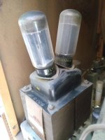
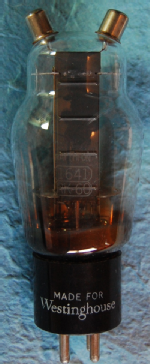
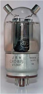
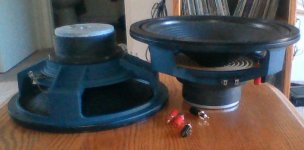
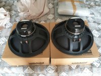
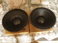
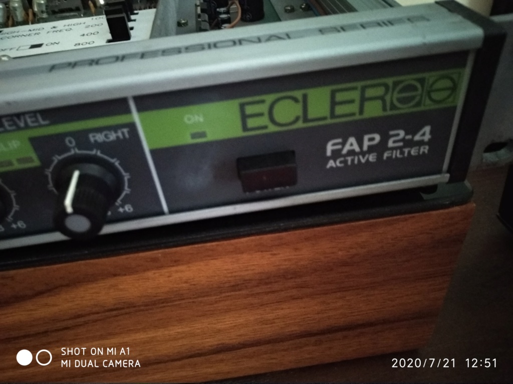
foto
Облако Mail.Ru - облачное хранилище файлов

Arcam AVR250 receiver

For sale is Arcam AVR250 surround receiver . The receiver was restored and refurbished along the outline provided by Condor Audio. Rectifiers were changed to 3Amp Schottky and all the caps on the main board were changed to quality (mouser) 105 degree units. Receiver played fine for a few days and again dropped the digital correction DSP modes . There must be a cold solder somewhere on the board still. I'm done playing with it. It plays fine in direct stereo mode so you can enjoy really good sound Arcam is famous for in two channel setup for a little outlay. The unit is in good , clean condition cosmetically . No remote
$80

Attachments

  • IMG_5561.jpg
    IMG_5561.jpg
    821.1 KB · Views: 163

Scanspeak 10F 8414G10 NIB pair EUR85

hello,
someone close to my place is selling 5 pairs of Scanspeak 10F 8414 G10, new in box. If we go for "group buy", he will sell them for 90CHF (about 85 euros) the pair. Not a bargain bargain, but still cheaper than in some shops (about 130 euros/pair). I want 2 pairs for me.

Who wants some? I can ship from either Netherlands or Germany, cheaper, but please be fast in deciding!

Best regards,
Erik

Upgrading the woofers to a linaeum bookshelf speaker

Just wanted to let people know I wrote up an instructable on how to upgrade the woofer in the RCA or Radioshack bookshelf speakers that feature the great sounding Linaeum tweeter.

Here's the Instructable: Upgrading a Linaeum Bookshelf Speaker : 5 Steps - Instructables

If you read and like my instructions and like them you can vote for me here:
Audio Challenge 2020 - Instructables
before the end of the day tomorrow 7/23.

Do I connect the microphone to my home amp?

I have been a home audio fan for many years.
I always knew how dangerous it is to use a microphone in an audio system, due to the issue of the couplings and their consequent damage to the tweeters. (the weakest point of the baffle)
For years I had on a waiting list to fix an old Sansui AU4900 amplifier that has an adjustable microphone input.
And also years ago I bought to give one of my children a good microphone since he studied classical guitar and wanted to record himself. It was never used.
So now I am trying to make it work, without success unfortunately.
A low impedance source coupled to a high impedance input should do this, but I don't get the slightest signal.
I replaced the XLR terminal on one end for the 1/4 "input of the (mono) plug in an unbalanced configuration. (2-wire, live and ground.
I leave the specs, hopefully someone can explain what is happening.
PA specialists, recording professionals?

Thanks in advance !


Microphone Sennheiser 815S :
Sensibility 1.5 mV
Nominal Impedance : 350 Ohms


Integrated amplifier Sansuí AU4900
Sensibility In- microphone : 2.5 mV
Impedance In : 12Kohms

Why gets the capacitor cooked ?

Hello,

on an amp with a KBPC3510 diode bridge and a 16V 15mF capacitor to get 10 V, 3.5A (worked for years without a problem) I could see ringing, tried all kinds of snubbers, C across diode, R+C and C||R+C but nothing worked.
Tried BYV29-500 (ultrafast rectifier diodes, If(av)=9A, trr<60ns) and the capacitor was cooked in 30 seconds, diodes are still o.k.
Please explain why and how to avoid it, Thank You.

Edit: all diodes are installed the correct way.
Edit 2: installed a new capacitor and it works now, I guess just bad luck...

Attachments

Plate amplifier DIY suggestions / plans

Hi All!

I bought a known faulty subwoofer as a bit of a project, the PSU & supporting electronics are beyond economic repair, but I quite like the chasi and the driver is in good condition - (Its a monitor audio radius 370HD for what its worth)

I'd quite like to retrofit a DIY plate amp design to its existing back plate and use it as is. are there any plans / open source PCB schematics that people recommend, looking for a minimum of 100w into 4ohms though the driver is rated upto 250w so more isn't an issue

I'm not at a level where I can design my own circuitry... (else I'd already be doing that!) - but I'd quite like to build my own DIY board where someone with a lot more understanding has done the PCB layout / schematic and I can build it up based on a recommended BOM - I see a lot of stereo designs but a little less with respect to subwoofer plate amps.


I hope you can offer some suggestions, or maybe point me in the way of a good challenge.

All the best

Reidy-

24volt Battery powered F5, ACA, Pre & Elect Xover for Boat

Hello, This is my first thread on Pass Labs but I have been following and dreaming of buying or building Nelson Pass components for awhile now. I would very much like to assemble these separate components but as I live on a Catamaran Sailboat I have unique opportunities that others on here do not have regarding space and power supplies. I wish to use all battery power for a stereo F5, a Pass pre, an electronic crossover and also Amp Camp amps either in the same case or the AC amps in the kit enclosures on here with the rest of the components in one 4U enclosure. Not only to save money but also to save space. I have a large 12 volt battery bank charged by shore power and also over 300 watts of delivered 12v solar panel output which I plan to double the size of in the near future. I plan on using 4 small 12 volt batteries wired to give the needed +/- 24 volts but hooked up to be charged separately with 12V through the use of power diodes.
I would like any help that others on here could give me to get this project started. I have noted that the F5, Amp camp amps, some Pass Preamps and the xover on here all run on 24 volts and in my situation I would not have to make or purchase power supplies for each individual component. This seems to make sense to me in my situation and I would like to get others opinions with much more experience than me to weigh in on any of the advantages and pitfalls of such a system.
My speakers are custom built-in boxes with Focal 5.25"s, SB Acoustics soft Dome tweets and custom 12db 2K passive crossovers all designed with WinISD which is a excellent speaker box and x-over design tool. I have a 60 watt Int tube amp and a 60 watt Int SS amp that I run Bi Amped through the Tape Loop and must say the results are astounding compared to these amps individually. Nelson Pass in one of his articles speaks of the EFFICIENCY of both Bi-Amping and electronic X-overs and how each gives a 6db increase which if thought of as only at the top end is huge. This is why I strive to make this system a reality for my use because of the efficiency of the finished system compared to the seeming complexity of the design and execution of these components together. This system would also run off the power from engines or solar while sailing which I use a car amp for now and to say the least is much less than desired when underway.
Thanks in Advance.

B&W ZZ12246 Repair

Hello, new person here and apologies if this has been asked before. I have a pair of B&W CM4 speakers that have been in storage for a long period. It seems that the bass drivers on both speakers have ceased functioning. Prior to going in to storage I recall the rubber edges were replaced. I've validated that the crossover in the speakers appears to work correctly, however when I pass a current through the bass drivers I do not see any movement in the cones. I tried the same test with the mid range cones ans these seem to work fine. Looking at the drivers themselves they look in perfect condition, the cones move freely and there is no obvious signes of damage. Anyone have any ideas, I think I'll pickup a multi meter to check the connection across the wiring...

FS: Hypex UcD400 HG with SMPS400A400 Stereo Power Amplifier

DIYclassd.com
DIYclassd.com
o Power: 2x 400W @ (8Ω) / 2x 240W @ (4Ω)
OpAmp: LM4562
Current limit: @ 20A
SMPS: 2x SMPS400A400
o Case: Modu Galaxy Maggiorato
o Parts:
Hirschmann Speaker Ports (ala Exposure)
Neutrik connector: PowerCon; RCA
* massive / High End ca. 1,5m Mains Schuko - PowerCon cable


Price: 250 EUR plus postage insured DHL shipping within EU (& GB)


And as always:
Private sale, warranty and exchange excluded.

(umpteenth) Audiolab 8000a upgrade

Hi,
so I just got this Audiolab 8000A (series B) in awesome condition and wanted to make some improvements and replacing time consumed components. So far here is my list.

1. Replacing the 10.000uf 50v Elna PSU caps with new ones. The choice is between Mundorf Mlytic 15,000uF 63v (30 euro) or Nichicon 15,000 uF, 63 V Gold Tune (18 euro). Now I've read rave impressions on the Mundorfs. Is it really worth?

2. Replacing the 6(four+two) Elna RE2s located close to the heatsink (power section) with four 47uF 63v (???not sure this is right) and two 47uF 10v. Which brand? Elna SILMIC II 47uF 10v? Nichicon Muse ES 47uF 10V? Here they are circled red (I guess?) I'm now wondering what is the white circled cap? Any idea? Should I change that one too?

3. Is it worth replacing the TL072CP 18nV with BB OPA2134 of 8nV will it make any difference and improve sound in terms of noise/distortion/clarity?

4. Replacing the 4 x 1n4002 rectifier diodes with HEXFRED Ultrafast Soft Recovery Diodes Will this change the amplifier response delay when it's turned on (it takes almost 12 secs to be activated from when I push the puwer button). No idea where they are located, can you point out?

5. Place new RCA plugs with Neutrik NYS367-2 and speaker sockets with some gold plated ones and hard wired with silver coated copper hook-up wire. Any brand suggestion? Belden ?

6. Any suggestion on the power cord? I may try constructing my own Mogami W3104 Cable perhaps but will it be any worth?

What other caps or components are a worthwhile upgrade?
I use the CD and Phono stage. Paired with modest Wharfedale Linton 3XP speakers.

Welcomed by a bug

Welcome

Found an interesting post here (Equal-pressure loudness contours) through a google search, which I wanted to reply to, so I registered, activated my account and wrote a reply. After I've written and click "Submit reply", it didn't appear, and clicking "back" didn't bring the text back. So that was quite irritating. Let's see if it writing a new post works better.

/Techno

Need Pair of Passive Near Field Monitor

Hello,
I have migrated from an acoustic piano to a digital stage piano and need a pair of near field monitors. These speakers will be placed each side of the keyboard at the rear of it and point towards me about 08.m from my ears. (Be able to see them out of corner of my eyes)

They need to be as small as possible based i guess a maximum 4/5" driver with a foot print of not much bigger than about 150mm, although they can be upto 0.5m tall. I guess a driver pointing vertically with the sound deflected to the horizontal might also be worth considering?

Any off the shelf speaker would consider, but i am woodwork handy so happy to make a pair if someone can recommend a driver and cabinet design please.

Many thanks imk

Attachments

Energy storage in non isolated amplifier PFC stage

I'm thinking about making a non-isolated plate amplifier for subwoofer usage (top end pro 18/21" cabs). The audio inputs will be isolated but the speaker output will not be, a RCBO will be utilized on the line input for ensure safety and no non isolated terminals will be externally accessible. The aim of this is to reduce the parts count, size and increase efficiency.

In terms of the power supply my current plan is to use an interleaved PFC stage with a continuous power throughput capability of 3.5 kW to make a soft regulated 400VDC bus which will power the amplifier (bridged low switching frequency IGBT class D). I haven't designed a PFC before so I have a few questions:
1) What restrictions are there on the maximum output capacitor size on a boost PFC? (this is where I want to store energy for transients)
2) How easy is it to current limit the line voltage? (IE I would like to not exceed 13A average line current) (considering normal boost converters may be impossible....)
3) In the circumstance that the line current is limited the output capacitor bank will begin to sag, this would seem to be problematic if it goes below the peak line voltage?

So considering this am I just better boosting to a higher voltage and using a buck converter to perform the current limiting and limiting of the maximum sag on the PFC output capacitor?

Rockford fosgate bd1500.1

Hi, got this amp in with blown output FETs.
Ordered in some parts, installed both new 4420 and optocouplers. All signals were verified with output FETs out of the main pcb. On one 2211 (u9) pin 7, the signal was a bit fuzzy/ring down but not to distort the drive signal. The opposite signal was perfect. I went ahead and installed the output FETs, amp powered up nicely.
Whilst powered and checking the gain the pot, I noticed the amp would get extremely noisy beyond half way on the gain pot (~ 32v rms at the output). I backed it off a bit until where I just about started losing the sine wave on the output. Whilst attempting to verify the drive signals I accidentally shorted one of the output FETs and I blew a couple.
I then returned to square one, removed and replaced components as I went along returning the drive signal. I am out of output FETs, 2240 and 2211, which I have on order.

However I noticed a clean square wave on pin 2 of U9, but it gets fuzzy at its output pin7. Same as earlier before I soldered in the Output FETs. I checked the resistors and capacitors around the 4420 and U9 but all check ok. I’ve attached a couple pics of the waveforms. The first pic is the signal entering the 2211 at pin 2. The other pics are pin 7, pin 1 on the 2211 and the gate pad of the FETs. For now I’ve got to wait on parts, but seeing I had a fuzzy drive signal at first and still has, is there something I’m overlooking?

Attachments

  • 61BFD41D-34F7-40B2-AE6F-B188D569E6E4.jpg
    61BFD41D-34F7-40B2-AE6F-B188D569E6E4.jpg
    994.6 KB · Views: 97
  • 1AF18E77-3E98-4E82-A7D4-17592E0635CB.jpg
    1AF18E77-3E98-4E82-A7D4-17592E0635CB.jpg
    998.9 KB · Views: 99
  • 4AE6CCD9-52A5-41C8-AAD5-92F47A696ADE.jpg
    4AE6CCD9-52A5-41C8-AAD5-92F47A696ADE.jpg
    994.1 KB · Views: 90
  • 71E9F56B-EB57-49BE-800F-1550C43E4F34.jpg
    71E9F56B-EB57-49BE-800F-1550C43E4F34.jpg
    991.9 KB · Views: 91
  • C79A7103-CDA4-46BB-A281-649DFA0B4140.jpg
    C79A7103-CDA4-46BB-A281-649DFA0B4140.jpg
    993.9 KB · Views: 92

About a phono preamp

Hello

Here is a phono preamp using the LM318 but at pin 1 and 5 it use a super-matched LM394 transistors pair.

The LM318 are a fast op-amp with no rise of distortions in high frequency or at very low level, its an old but good op-amp.

There is more modern op-amps but most of them do have a strong rise of distortions in high frequency or at very low level.

This circuit use an external LTP input to keep the speed but not the noise.

Any opinions, ideas ?

Bye

Gaetan

Attachments

  • LM318 phono.gif
    LM318 phono.gif
    57.6 KB · Views: 1,133

LM3886 BTL Configuration. Help needed

Hello, good evening to y'all
I'm a senior ECE student and currently working on my graduation project, in which I need to design a power amplifier circuit to drive a subwoofer, long story short, the signal I'm amplifying is a single tone of 50Hz, and the power being fed to the speaker is in the range of 100-120 watts
I'm using a single-tone generator in the first stage followed by a preamp to bring the signal level up to an adequate level then the power amplifier will provide the wattage gain.

I have attached an image of the circuit design I have built which I'm pretty sure has alot of flaws and I hope someone can help me with it because I actually feel lost and can't really be sure if this design will work in practice.
Thanks in advance

BrWVsAh

This is how they make torroids!! Cool!!

Haha, I know its old video and I am slow... But its cool to see this is how they made the toroidal transformer we use.

toroidal winding machine -toroidal winder -current transformer winding machine winding machine - YouTube

Imagine doing this by hand!! It would have been a crazy task.

I challenge anyone to try fitting this into your amp!!

Напольный станок тороидальной намотки для особо крупных размеров - YouTube

Possible to get digital in on this CD? - anyone with experience pls give your thought

I have a very nice old CD player (Xindak MUSE 1.0 Tube from 2005)

This player has 96/24 DAC and tube on the analogue output.

I wish that there was a way to ad optical/coax in to this CD player to make use of the DAC and tube output from my other digital devices like that Airport Express.

Does anyone know if this is possible, or how much time this would require from someone with the knowhow?

I have seen several threads about this topic on other CD players, and think that it seems doable, even if i lack the skills with the circuits i can easily handle the soldering and other such related stuff.

I added some images, of the text where the CD transport connects to the DAC/analoug part of the PCB.

Anyone knows if there is simple I2C connection here (or what it is called) or if another solution is possible? I am very thankful for any insights.

//GF

Attachments

  • IMG_9465.JPG
    IMG_9465.JPG
    127.2 KB · Views: 137
  • IMG_9464.JPG
    IMG_9464.JPG
    108.8 KB · Views: 145
  • IMG_9463.JPG
    IMG_9463.JPG
    150 KB · Views: 138
  • IMG_9450.JPG
    IMG_9450.JPG
    137.2 KB · Views: 144
  • IMG_9449.JPG
    IMG_9449.JPG
    137.3 KB · Views: 135
  • IMG_9448.JPG
    IMG_9448.JPG
    150.2 KB · Views: 66
  • IMG_9447.JPG
    IMG_9447.JPG
    148.6 KB · Views: 60
  • IMG_9446.JPG
    IMG_9446.JPG
    124.2 KB · Views: 66

Need help replacing this Inductor

I am pretty sure this would be called a common mode inductor...or choke?
It's on the power supply board of my shop window AC unit, (LG 18000 btu, 230v)
Had a "friend" helping me service it and...oops.
I got the inductor removed but I can not find it online based on numbers on sticker. I can't find schematics for psb either.
So, is there a way that I can determine the "value" of this inductor so I can order a replacement?
I do not have an induction meter...just a multimeter.
EDIT: The pin pitch is 10x13mm

Thanks in advance!!

D9u7OgG.jpg

xB1KYyt.jpg

oLKqvB8.jpg

RNoFS6Z.jpg

Perceived stereo separation

Many years ago(at least a decade), I had heard a speaker setup that struck me due to its stereo separation. I can't remember any specifics about it, but sure it was something to do with psychoacoustics. The best way I can describe it is that I was able perceive stereo audio where the source was physically in excess of the speaker location itself, where the sound is about 1 foot in extension of where the speakers actually are.

In a normal setup, the most "left" or "right" I could hear a sound is directly where the left or right speaker is. Let's just talk "left" for example. My initial assumption is that I perceive the left's speaker's position as a function of how much sound also bleeds into my right ear, either directly(well, around corners, although stifled) or indirect reflections. It was in an open area so I doubt very much reflections came back. I was standing only 3-5 feet from the speakers themselves.

From there, I assumed that if I just simply inverted the phase of that signal, attenuated it, and broadcast that through the right speaker, maybe that would cancel out how much reaches my right ear and trick me into thinking it's more left. That didn't work for maybe obvious reasons to some. I looked into phase, delay. Perhaps it is the Haas effect, but I couldn't replicate it(seems that was more about trying to make a mono signal stereo-ish, no so much "enhancing" stereo).

I'm wondering if anyone knows what I'm talking about, and could point me in the right direction to learn more about whatever signal processing was involved here.

FS Ciare NDH 15-4S, NIB

For sale a pair of NIB Ciare NDH 15-4S 8 Ohm loudspeakers.
New, never used or connected, in original boxes.

Price: 450 EUR

Shipping from Russia, 60 EUR to Europe, 70 to Americas, registered airmail with tracking.

Buyer pays paypal fees, offers are welcome.

Attachments

  • 20191002_124246.jpg
    20191002_124246.jpg
    973.2 KB · Views: 238
  • 20191002_124430.jpg
    20191002_124430.jpg
    546.9 KB · Views: 202
  • 20191002_124407.jpg
    20191002_124407.jpg
    953.8 KB · Views: 268
  • 20191002_124424.jpg
    20191002_124424.jpg
    956.3 KB · Views: 201

Midwoofer problem

Hello, i have 9" midwoofer that i measured few centimetres distance distance in free air and in cabinet,

as you can see there is something weird going on at 450hz-850hz when the midwoofer is in a cabinet (sealed), i have 2 cabinets i have tested them with, both should an ideal size so the problem is not there.

I have both of these models and they do the same problem.
http://www.sievers-audio.de/chassisdaten_m/mw265.pdf
http://www.europe-audio.com/datasheets\morel\mw267.pdf

so trying to figure out if i can and how to fix this problem.

Attachments

  • miim.png
    miim.png
    42.5 KB · Views: 124

Modding an existing small sealed 2-way/ driver advice

So I have a pair of active BlueSky SAT6.5 with one of the woofers blown, so i decided to make it a nice little DIY project for sealed nearfield.

Amp on each is 2x100W, crossover at 1500Hz.

The is pretty small, but has an internal panel to separate amp from drivers. I'm thinking of removing it to increase the volume at least 2 liters.

I've narrowed it to three woofers:
Dayton RS180 (4ohm, aluminium)
Dayton Audio RS180 - 7" Woofer
Dayton ES180TiA (8ohm, aluminium)
Dayton Audio ES180TiA-8 - 7" Woofer
SEAS H1224
SEAS H1224-08 L18RNX/P - 8" Woofer

RS180: cheap, low FS, low EBP. However, low power and needs 12 as much volume as i have for spec'd F3, and a bit low-powered for the amp.

ES180TiA: high power, F3 @71Hz at merely 5.3L which is about as much as i can get from these boxes.

SEAS h1224: i like how they sound in amphions. but those are ported, and drivers have high EBP and high Fs. also madisound says "sealed not recommended"

not yet decided on the tweeters but eye-ing
Peerless DA25BG08-08
Peerless by Tymphany DA25BG08 - 1" Tweeter

Also Dayton ES
Buying a Dayton Audio ES25Nd-4 tweeter? - SoundImports
what i'm vary of is i didn't like the existing peerless ring-radiator - so i might just not like ring radiator tweeter conceptually?


I don't think i want to build a larger box or buy new amps because this is supposed to be "take some trash and make something cool with it" project, so i'd rather retrofit existing boxes and reuse existing amps.

Also my main monitors are ported 3-way, beryllium tweeter (xover 280 and 2400) - so this is really meant to be exact opposite of it in character - sealed, alu (or silk dome) tweeter, 2-way with different crossover point, so everything fits the bill i just need to find decent drivers.


Side note, I also blew one of the amplifiers when measuring voltage output. at 35V the fuse blew, and when i swapped it it blew again. it's already in service tho.
Does anyone have any tips on how not to blow up amps when measuring voltage output?

Newb TL questions

Good afternoon,

I'm really terrible at making things by hand (dyspraxia) but now I have some experience with 3D printing, I'd like to take a crack at making a transmission line speaker. To keep things simple, I plan to use a single Tectonic TEBM65C20F-8 driver in each one and design it so that it bolts together with no finishing required beyond some soldering.

I've been reading up on transmission line design and used the mh-audio calculator but I had a couple of questions that Google and searching this forum couldn't answer before I proceed to the design phase:

  1. Is the only factor in the profile of the line its surface area? I was planning to use a circular profile and work out its diameter by taking the mh-audio values for width, turning them into surface areas and then working back to an equivalent circle diameter. If a circle is a poor choice, is there an optimum aspect ratio?
  2. Is there a good starting point for the placement of damping material on the line? I'm aware that it benefits from experimentation but ask because in the diagrams, it seems to cover the half of the line 'furthest' from the driver.
  3. Because I'm using FDM, I can vary the density of the walls, would a solid wall between each section of the line (where it doubles back on itself) be better or would a double wall with a filling between reduce transmission of sound through the walls? I can make the filling between them a 3D structure similar to rigid open cell foam at a larger scale.
  4. I was planning to flare open end of the line slightly at its end, should my line length be calculated to the start of the flare, the end of it or somewhere in between? Alternatively, is this a terrible idea entirely
Thank you very much for reading, I'd appreciate answers that direct me to recommended reading or search terms every bit as full ones for each point and would also greatly appreciate any corrections on the terms I'm using. If I can get anywhere with this, my next goal would be to make a two way speaker but I thought it best to start small.

Also, if anyone is working on a project of their own and would like some components 3D printing, I'd be happy to help.

Low voltage differential psu preamp

hi guys, im building a modular preamp with s typical differential psu (15-20v positive/negative) and modularized active circuits so i can try different designs, and besides the usual discrete suspects the tubes are definitely on my radar.

So im wondering if theres a well documented low voltage tube (or hybrid) preamp that uses differential psu. The only one ive found is the borbely headphone amp but im told its not a safe design?

Thanks in advance 😁

Electric Beach Frugal Horn FH3 with Alpair 7.3

aAbuW

qLq2


Electric Beach FH3 speakers with Alpair 7.3 and Audio Note silver wire internally.

Premium professional build of these excellent speakers. These have served me well but I have now replaced them with larger single driver TQWT boxes.

I have the original shipping boxes but would equally welcome local pick up.

Get in touch if interested. Looking for around £375 plus shipping.

DIY impedence matched output headphone amplifier help

So recently I bought a pair of cheap open back headphones, since I never experienced the "open design that allows ambient noise to seep into the ear cups. This typically creates a more immersive sound."- Open-back vs Closed-Back Headphones: Which one is best for you? - RTINGS.com


The headphones are the Superlux® HD668B Superlux HD668B Professional Studio Standard Monitoring Headphones - Newegg.com


Superlux HD 668B Review - RTINGS.com


The issue I'm having comes from using the headphones with the headphone output of my amplifier . Which is quite unbalanced for the 56Ωx2 drivers. While playing music,games,movies,etc... I have to turn the volume up past 40 on the amplifier to even get sound to come out of the headphones, and for a thrilling experience I need to turn it almost to max. I cant help but feel this is doing a number on the poor preamp section of my amplifier.


So my question is can someone please help me design a low noise, ultra linear stereo headphone amplifier that is matched to the impedance of my new headphones. I don't have any experience with designing IC amplifiers but I have soldered kits for them before. For this project I have a variable split regulated DC power supply rated at ±15v 1a. and I will be using a 1/4" TRS for the signal out. the input impedance needs to be around 50k for my sound card.


I'm really sorry if it is rude or against TOS to ask for help like this on here, if it is please just ignore my post. like I said though my IC amp circuit design leaves alot to be desired, and I hope I can find some help here.


(TL,DR) i need a headphone amplifier design that will power 56ohmx2 headphones at 300mv

Trace Elliot V-type Bass Combo

Hello

Recently I bought from secondhand an Trace Elliot V-type Bass Combo (model 5001, 300W, build 1996). The combo is sounding verry good but it has one problem. It has verry loud 50Hz hum. It is disapear if I set the gain or volume at minimum. I have opened it and I saw that the power modul (bipolarbear) has been repaired - the output transistors were changed (now are BD249C and BD250C). From the service manual they must be 2SA and 2SD typ for 300W. Then i measured the DC offset and it was 0,5V. I tried to set it down but the minimum I was able to set it was 150mV.

Strange thing is that the power amp itself don't hum and the preamp is also quiet when is connected thrue DI.

Can somebody give me any advice how to repair this annoying hum?

Cheers

isolated ground pedalboard DC PSU - multiple bridges on one winding?

A friend, who is into guitars, asked me to build him a pedalboard PSU. I took it as a challenge, it is kind of out of my comfort zone 🙂 .
But he wants it to be made with isolated grounds on the channels. I kind of understand the concept - and why it is needed - , but have never seen such a device open or its schematic, so I don't know how to approach such project. Anbody?
The pieces in serial production are probably made with SMPS, but this is well beyond my time and knowledge (I think it would require extensive study and testing). So it would be more of a "classical" design with a big bulky mains TR, which is then rectified, filtered and regulated.
And there the question arises: should I use a separate TR secondary for every DC channel or is is it possible to have only one secondary, but then multiple bridge rectifiers attached to it? Does that give me the needed isolation? Could the noise "bleed through" the bridge? Should I expect trouble? Thanks ...

Using a Scope to setup your turntable

Does anyone know how to use a scope for setting the tonearm for your turntable?
I have a new Pro-ject essentials lll table and it only has the little weight and fishing line for the anti-skate. I’d like to check it with my scope to see just how well it works. My older tables do a much better job with this as they use a dial for this.
So any help with how I can use a scope to see just how far off or not it is would be great. I have one of those set-up LP’s from Shure and it works pretty well and it tells me that it’s not set correctly and with the way Pro-Ject has this setup is not a very good system
Thanks
Adjustments.jpg
IMG_5381.jpg
IMG_5382.jpg
IMG_4850.jpg

Subwoofer Impedance - Simulation vs Reality

I am making my first subwoofer, and my goal is really to understand the physics of what is happening. I am happy to get advice on rules of thumb that end up generally producing good loudspeakers, but I would really appreciate advice on how to methodically understand what is happening as I fine tune my design despite not having an anechoic chamber.

I bought a Umik-1 Calibrated Microphone and a DATS-V3 for this project. Before I started I thought the process was:
  1. Simulate a cabinet that achieves the response I want based on the manufacturers published specs.
  2. Buy the driver, break it in and measure its actual T/S parameters
  3. Adjust the simulated enclosure dimensions, port length, etc to achieve the desired response.
  4. Build the enclosure.
  5. Test the loudspeaker in two ways (A) with a measurement microphone. Keep the microphone very close to the driver to reduce the effect of room reflections. (B) Test the impedance of the loudspeaker.
  6. If you are happy with the loudspeaker you are done. If you are not happy continue.
  7. Adjust the simulation so that it agrees with the results from step #5, this likely involves tweaking the port length, volume of the box, and Ql, Qa and Qp.
  8. Once you have this more accurate model of the loudspeaker you can make variations of that model to find something that should have a better response, return to step #3.

During my build I ran into some problems. Specifically on step #7. I got an impedance graph where the resonate frequency seemed to be right, but the magnitudes of the impedance were not scaled as I expected. The observed peaks were twice as large in magnitude, as the simulated peaks.

Question 1: Is it reasonable to expect the impedance to match between simulation and real life? Can the room change the impedance?
Question 2: Is there a way to measure Ql, Qa and Qp once you have built an enclosure? I noticed that varying these three quantities could shape the impedance of the speaker, but in order to match simulation vs reality I had to use insane values (QI=1000, Qa=1000, Qp=5) whereas I am told (QI=10, Qa=100, Qp=100) is more reasonable.

Attachments

  • simulated_impedance.png
    simulated_impedance.png
    77 KB · Views: 133
  • measured_impedance.png
    measured_impedance.png
    41.4 KB · Views: 135

Modelling an 80 liter subwoofer using WinISD // Transmission line simulation

Hello

I'm in the process of designing a subwoofer to house my old car sub, a Hertz ES 300D.

I've settled on 80 liters of internal volume and I'd like to reach atleast 100dB of output before cone / power limitations, preferably as flat as possible and getting usable response at 20hz.

I'm currently modelling the model in WinISD and I realised multiple small round ports are vastly superior to using one long slotted port.

However this is only the case if I tick the " Use transmission-line model for port simulation". Disabling this doesn't change the slotted port version much, but drastically changes the small round port model.

Slotted port (tuned to 22hz. Blue legend):

400mm x 40mm, 130cm long

Multiple round ports (tuned to 35hz. Orange legend):
4 x 57mm diameter, 27cm long

I've added multiple EQs to get the response flat. Heres the response with the transmission line model sim turned on:


An externally hosted image should be here but it was not working when we last tested it.


Here's with the transmission line model sim turned off:

An externally hosted image should be here but it was not working when we last tested it.


Not only is the response much different, the cone excursion is absolutely out of bounds with the multiple round ports. If disabling the transmission line sim is closer to reality, this design is horrible.

What gives, what should I trust?

I have some additional questions; The sub is going to be in an apartment room, roughly 4.5m x 3.5m x 2.5m. How will room gain influence the response? I'm assuming it will boost the low end significantly.

Learning FM alignment - Sony STR-7035

Hi,

I have a Sony STR-7035 that I purchased for parts to restore, and that I wanted to use to practice what I have been learning online and with books about FM alignment. The alignment procedures for this particular receiver in the service manual seemed simple enough, and I used the opportunity (we all need a 'reasonable' excuse) to purchase a Panasonic VP-8193 signal generator, which does also multiplex.

First, I had very poor reception, which resulted to be a gain issue in the first IF amplifier due to an open base to emitter junction in Q201. This solved the poor reception: I was able to align the IF stage as for service manual, zeroing AM and maxing the FM signal across C217 at the FM detector. I was also able to obtain full deflection of the signal strength meter with a 60dBuV unmodulated signal, which is what the specs call for.

Now, the issue is that there is something wrong with the stereo section of the receiver: I do not seem to get stereo, all the adjustments are unresponsive (apart from RT501), Q303 (38kHz amplifier) appears to always be off, regardless of the strenght of the incoming signal, and the collector of Q302 shows always a wrong voltage of 7.7V DC. Here is where I am stuck.

I checked all the transistors, resistors and capacitors in this part of the circuit, and they all work and are in spec. I replaced all the electrolytic caps just in case. If I inject a 19kHz signal from an audio generator directly to the base of Q301, I get an amplified signal at the collector; I also get a very very noisy 38kHz signal at the cathode of D301 and D302. Regardless of the amplitude of the injected signal (up to a few volts), I can only get a maximum DC voltage of about 0.63~0.65V at the base of Q303, from a 200-300mV with no signal and about 20-30mV with the stereo switch in the mono position.

If I use the pilot signal from the RF sig. gen. injected to the antenna terminals on a 93MHz carrier, I can't see any decent 19kHz signal downstream of the detector, but I see a very weak very noisy signal (80mV pk-to-pk), almost impossible to trigger on the scope. I have now run out of ideas. I even tried looking at the frequency response of the front-end and IF stages, and there is a lot of filtering going on: a carrier FM modulated with a 400kHz signal (I think I set it at 60dBuV) gives me a 400mV peak-to-peak at the detector, but 200mV with a 4kHz modulation, and it carries on going down as I increase the frequency, to nothing visible at 19kHz.

Does anyone have any idea on the possible issue, or what else to check and try?

Attached are the section of the circuit, the 38kHz signal at the cathodes of D301-D302 when I inject a 19kHz signal at the base of Q301, and the same when I use the pilot tone modulating a 93MHz carrier injected to the antenna.

Attachments

  • Capture.JPG
    Capture.JPG
    196.3 KB · Views: 166
  • IMG-4798.jpg
    IMG-4798.jpg
    766.4 KB · Views: 166
  • IMG-4807.jpg
    IMG-4807.jpg
    833.5 KB · Views: 155

Cartridge recommendations for a Garrard Lab 80

Hi

I currently have a Garrard Lab 80 and was looking for some recommendations for carts. I play a lot of bass heavy music such as dub reggae, Steppas etc. I currently have a Share M44-7 and a AT95ex but feel I could do better. I am currently looking at the Audio-Technica AT-XP7 but I am very open to suggestions. I will be using this with my sound system sometimes so I do need to think about a heavy tracking force, saying that I could use a Hi-Fi cart at home and use the M44-7 when I am out, but it would be nice to be able to have an all in one cart so I didn't have to swap it about.

  • Locked
Crimson electric AMP “garage find”

I really don’t know what it is except that’s it is a Amp

Black box with brand crimson electric ( looks old)

When opened I see a Holden & Fisher transformer 250va sn813194
There is a small circuit board from crimson electric
There are two Toshiba transitore and 4 capacitors,

As I have no use for it I just want to sell it, i have no references for pricing

Part is located in the Netherlands and shipping will be at buyers cost

If you’re interested and want to receive Some photo’s or want to make an offer feel free to send me an email on <redacted email id>

Regards Chris

Upgrading a simple Class A amplifier with better components

I just bought a class A amplifier, that comes with a separate case with power transformer.
This component shows I think the important audio signal path.

1. Which components here might be worth desoldering and replacing with higher audio grade components?
I've heard good things about capacitors from: Nichicon KZ Muse, Nichicon KG gold Tune and Elna Silmic II.
Is it possible that I would hear better audio if I would replace these caps with "better, audio grade" caps?
I love soldering so if theres any chance I will take it! 🙂

2. In persuit of higher quality audio, am I allowed to simply ENLARGE the voltage or the capacitance (or both) without any riscs?
I want warm mids, deep base, and enough headroom for momentary energy going to the voicecoils of the speaker (active system, so no passive filters inside the speaker).

3. What are the two blue potentiometers for? I asked the distributor about what these are/do, and he simply replied:
"Please don't touch them: the designers have tested every single model by hand before shipment!"
So upon receiving the amplifier, what should I measure where, with my voltmeter sothat I can check (over time) that the potentiometers are indeed set correctly?

Thanks!

HTB1raqgSFXXXXbKXXXXq6xXFXXXg.jpg

Eminence Alpha 15A vs. Goldwood GW-1858

Hey any of you guys tried the Goldwood 18" GW 1858 and the Eminence 15" Alpha 15A on open baffle?

I looked everywhere on the ENTIRE internet lol, and nobody has posted the characteristics between these 2 cheap high QTS drivers in OB? I know Martin King documented designs with them (The 18 plays louder and lower) but there is no description of the sound difference. I want to give a crack at a pair of those 18" on another system for fun, but is it as fast as the 15A? I just want to find out if the 18" perform better than the 15" on the same U baffle up to 500hz?

Thanks in advance!

Building a boombox with leftover car audio-schematic check

Hello all, title kind of says it all. I'm sharing a schematic for anyone to chime in of a build I'm in the middle of gathering stuff for. Trying to keep things on the lighter weight side by not including batteries for power storage. This will mainly be a shop box. Am I oversimplifying the wiring? Should I be concerned about noise in my speakers from the power supply? Looking for any insight from those of you with more experience than me. I'm kind of new to this. Thanks

Attachments

New Sticky on Universal Power Supplies?

Can I suggest a new sticky with links to info on building the Universal Power Supply for different voltages, etc? There is a lot of info about that here, but it is very hard to find. E.g., the new Korg B1 needs a unipolar +24V, and I'm sure there must be some info about how to get that from the 'UPS', but where? (Yes, I know I can just use a wall wart. It's an example.)

High-pitched whine from DIY mixer

Hi guys,

I tried to post this a while ago in a different subforum, but I realised that was the wrong one so I am reposting here - hope that's ok.

I recently made my own small 3-input stereo mixer for use at my desk so I can simultaneously have all of my computers connected to my speakers. The thing works OK and I'm pleased with it, but I am getting a high-pitched whine out of it that becomes noticable at fairly high volumes - it's honestly not hugely disturbing most of the time. However, I am not an expert with this stuff so I was wondering what the problem could be? Is it ground loop related? I have the mixer powered from a wall USB PSU, and I have 2 computers and an "Aux" connected to it. The whine seems to persist regardless of what inputs I have plugged into it. The speakers I am using are powered PC speakers, and they do not whine if I disconnect the mixer and plug in a different device with the same cable.

Here is a schematic of my design

Here is the PCB layout

If anyone has any ideas for why this might be happening, I'd love to hear them! Thanks in advance.
Projects by fanatics, for fanatics
Get answers and advice for everyone wanting to learn the art of audio.
Join the Community
507,781
Members
7,888,175
Messages

Filter

Forum Statistics

Threads
406,225
Messages
7,888,175
Members
507,781
Latest member
Ronny2001