Add a digital out to Roland JP-8000 synthesizer.

I want to add a digital output to a Roland JP-8000 digital synthesizer which has only analog outputs. The form of the digital output does not matter, as long as it is possible to record the digital output directly.

In the following video it is possible to see the main board, along with the digital to analog converter at 15 minutes 20 seconds.

Roland JP-8000 Repair No / Low Audio Output - YouTube

The DAC is a NEC UPD63200, the datasheet can be accessed at UPD63200 Datasheet(PDF) - NEC

The JP-8000 service manual with some details on the circuit including the main board (starting at page 19) can be accessed below.
https://www.synthxl.com/wp-content/uploads/2018/04/Roland-JP-8000-Service-Notes.pdf

How to complete this mod and which parts do I need?

Free KEF Reference 104.2 for a good home

Hi guys/gals,

I have a pair of KEF Reference 104.2 vintage speakers. They sound very good, little outside wear, and was a very highly regarded speaker in its days. Internal dual woofers, with a d'Appolito pair of mids with a center tweeter on the front.

It has the usual issue: dried out ferro-fluid in the tweeter, so the treble is a bit attenuated. To restore it you need either to replace the tweeter, or clean out the air gap and put in fresh ferro-fluid. There are several threads here on how to do it; I've done it on other speakers and it's not a big deal if you can work carefully.
A replacement is here: MW Audio MT-1191: 1 inch Dome Tweeter for KEF 104/2 Speaker | Midwest Speaker Repair

I don't need the KEFs and they are free for pickup in Belgium, Antwerp region.

Jan

Attachments

  • kef.jpg
    kef.jpg
    73 KB · Views: 260

Bass reflex ports - Monacor

So I've used these several times and having just used them again an element of doubt is creeping in as the ports are actually slightly tapered over the length.

My question is when modelling in WinISD is the inside diameter they specify the one I should be using given its taper?

If the images aren't clear the specifications for this particular port are:

Inside Ø29mm
Outside Ø49.5mm
Length 123mm
Flange Ø52mm
Area (SV)6.6cm2

Attachments

  • G128610A.jpg
    G128610A.jpg
    22.9 KB · Views: 188
  • G128610Z.jpg
    G128610Z.jpg
    16.7 KB · Views: 193

A primitive PCM2704 PCB no longer detected as a USB device, is it fixable?

I have a very basic and bare PCM2704 USB DAC:


0SJur3u.png


It worked fine for over 4 years feeding the subwoofer amp in my car (I didn't think the sub needs a more sophisticated and expensive DAC, given its range of 15 Hz to 50 Hz - which may not be reasonable assumption, but I digress). And suddenly I noticed that the sub isn't playing, and traced it to the PCM2704 not being detected as a sound device (nor, it seems, as anything else). Tried different PCs and different cables, no change. The LED lights up, but no sound device detected by the PC.

I understand it's a cheap device, but it's not free and I could use it in different applications so if it's fixable I would prefer to repair it. Is there any known cause for this failure? Perhaps, the quartz oscillator is broken? Or do you think the 2704 chip itself has to be replaced? There is no visible damage of the board.

first Time Build Accuton Active 3way

Hello

This will be the first set of speakers I have built

2 Closed Boxed Cabinets - Using 1" Baltic Birch

Accuton Drivers
C30-6-358 Tweeter
C168-6-990 Mid
AS250-8-552 Bass
DSP 192-4-111

I have modelled the cabinets with BassBox. I am looking for any advice from experience builders to make sure my selection of drivers are a good match for each other and the cabinet size for the mid will work.

Bass Cabinet

Shape: Prism, slanted front
Vb = 45.64 liters
Qtc = 0.563
QL = 7
F3 = 53.04 Hz

Mid Range Cabinet

Vb = 2.672 liters
Qtc = 0.441
QL = 7
F3 = 236 Hz

I am pretty sure size for the Bass cabinet is ok for size but not too sure the Mid because of the QTC. Some of the post I read makes me think I do not need to worry about the QTC for Mid cabinet.

I am in the process of building the DSP in a cabinet now. I plan to use 1-rst order of 3500 for HP filter and 300 for LP filter.

This something I plan to take my time doing over the next 2 years and these speakers are to replace my apogee scintillas which I really liked the sound but I am now needing to replace the bass panel so I want to make sure these speakers are designed properly and make me as happy as the apogees.

FS First Watt B1 Transfomer Buffer Preamp

I'm selling First Watt B1 transfomer buffer stage.
I bought it from someone in US. I'm in south korea but item will ship to wordwide.

Price is $600 (include shipping cost to wordwide).

you can see more information from below link.
Burning Amp 2017 - Nelson Pass - YouTube

Attachments

  • 20200511_171951215_94230.jpg
    20200511_171951215_94230.jpg
    506.8 KB · Views: 612
  • 20200511_172010154_63290.jpg
    20200511_172010154_63290.jpg
    380.7 KB · Views: 618
  • 20200511_172021673_36040.jpg
    20200511_172021673_36040.jpg
    447 KB · Views: 1,026

SLAPS for SLAM!

The SLAM! AMTs I built have a high efficiency (100 dB/ 1 W / 1 meter), so I don't need that many Watts to drive them.

I'll be quite satisfied with 4 Watts, the AMT's resistance is 6 ohms, so 4.95 Vrms is sufficient.

The AMTs also have an outstanding resolution, but they are at the same time merciless in revealing any amplifier's misconduct.

My current 25 W class A amplifier is no exception.

I've been suggested to give up on complex amplifiers and instead try something simpler and with no feedback at all.

This is the SLAPS (Split load phasesplitter amplifier) amplifier I've been suggested by Circlomanen:

An externally hosted image should be here but it was not working when we last tested it.


It amplifies only 2 times, so I need a pre-amplifier with 12 times amplification.

More to come...

Peavey Minx

Hi


I need some help with this Peavey Minx 30watts bass amp. It had its fuse blown. Upon checking, both the power transistors were blown. Its has a SJE2152 on the left and a TIP107 on the right. One diode thru the heat sink is SZ1388 and the other is 1N4003. Can someone please tell me which are the correct transistors and diodes to be used for this amp.I cannot find the schematic. Does anyone has. Please assist.


Thanks


Carlos

Should I change power caps in Nad c372

My nad c372 integrated has two bulging capacitors (1000uf 100v). I’m planning to replace them with Nichicon LKG series caps. And four power capacitors(10000uf 80v) looks fine visually. Should I replace them as well or let it be. If needed it’ll be replaced with elna lao series ones, will it be a possible upgrade in terms of audio quality ?. Also the ones that comes from nad are rated at 105c and the ones that I can find are rated at 85c. Is it okay to go with lower temp ones ?

Thankyou

Oops!...I Did It Again

To try to keep prices down I have sometimes bought a2d converters from China. Some ad9281's I bought worked fine.

On my current design I used a ad9220 and got a couple of samples from AD.
The first one worked fine.
So I bought a couple from China.
I built up a pcb with the Chinese one in it and it was terribly noisy at high speeds.
So removed the Chinese one from the pcb and fitted second AD one.
About 90% of the noise was gone.

It seems I wont learn buying Chinese cheap components.
I guess sometimes you get lucky and other times you dont...

Full range Drivers for a DIY Soundbar

Hi all,

Introduction
I'm planning on making a soundbar, because my tv-speakers are trash.
I don't want to spend more than 100 euro, but 80 would be perfect. I already have a big sheet of hardwood plywood. I did make a DIY boombox in the past, but i dont want to use car-speakers again because of the dimensions.

What do I want?
I'm thinking about a soundbar with 2 full range max 4" drivers. I do have a a 6" passive radiator laying around and I'm planning to use it to boost the low frequencies. It will be a little bit deeper and less wide soundbar than is common to fit the passive radiator on the bottom.
It will be powered by an 2x100w TDA7498 class D amplifier.

Picking Drivers
Now, I need to pick my drivers. As I live in the Netherlands, I cant use every american site to get drivers for cheap.
I was hoping that you guys can give your opinion about my picks.

1. € 10,40/piece: VISATON FRS 8 M - 8 Ohm
2. € 28,40/piece: Dayton Audio RS75-4 3" 4 Ohm\
3. € 33,45/piece: Tang Band W2-803SM 2" Extended Range Speaker
4. € 39,95/piece: Dayton Audio Reference RS100-4
5. ?

Maybe someone has a good suggestion for a good sounding driver between 10 and 30 euro's, I'm not planning on making a crossover.

Thanks for reading!

Attachments

  • DIY soundbar Design.1.jpg
    DIY soundbar Design.1.jpg
    192.1 KB · Views: 973

Is there an AVR...

Is there an affordable AVR where I can select /modify the target equalization response, I very much like my Anthem, but it insists on a mid-bass hump as the target. I can fix it's insistence on the sub being too high by just turning it down after eq, but it does not let me fix this stupid decision for "wow that bass" crap. Double bad with the advertisements who boost on top of that. Very unpleasant. Audessy does not eq flat either, and actually I don't care for it at all.
No, I don't want to by five more amps and add my own DSP between. Simplify. I just don't want someone else deciding how to screw up my sound.

4 Way loudspeaker project

4 Way loudspeaker project 15'', 12", 2" Comp., Tweeter

My new project is building a 4 way passive crossover loudspeaker stereo system.


The drivers are :
- BEYMA 15" 15LW30 Neodym
- BEYMA 12" 12LW30/N, same serie than de 15"
- 2" Compression driver + Horn (unknown for instance)
- Super tweeter


Fc will be 150 Hz, 900 Hz and 10000 Hz.

Attachments

  • Massive Audio CT6 180.jpg
    Massive Audio CT6 180.jpg
    248 KB · Views: 440
  • Massive Audio CT6 179.jpg
    Massive Audio CT6 179.jpg
    177.4 KB · Views: 439

Antek AS-4218 transformer with steel cover

Antek AS-4218 transformer pulled from a build less than a year old. My friend wanted an F5 turbo and I couldn’t use this transformer.

As-4218 - $51 value
Steel cover - $40 value

Asking $65 shipped conus only.

Attachments

  • 8F1298AD-BE91-43FE-800C-688032E01DF2.jpg
    8F1298AD-BE91-43FE-800C-688032E01DF2.jpg
    994.5 KB · Views: 263
  • 5399206A-D78E-4F4A-8CC9-FD3BC40917AD.jpg
    5399206A-D78E-4F4A-8CC9-FD3BC40917AD.jpg
    945.4 KB · Views: 251
  • 6BB9122B-8D68-4593-9D6E-F04982C4D686.jpg
    6BB9122B-8D68-4593-9D6E-F04982C4D686.jpg
    943 KB · Views: 247

Advice on any more efficient 2 way kits

Hello. I’m building a 20 seca amplifier and am going to need to do some suitable speakers. I’m hoping to find a well tested 2 way design or kit, horn or more conventional designs are equally interesting. My room is small, I’d like to get down to 50hz. I was looking at the frugal horn but I’m not convinced that the broad range driver approach will work for me.

If anyone is aware of any designs along these lines I’d be grateful for a steer.

Thanks. Kris

Looking for a tube tester to use in Denver area I can use.

Hello

I used to have a great tester. A Hickok 539c . Then I thought I would never have tube stuff again. I sold it. Stupid me. I was wrong.

I have a few 6DJ8/6922/7308 military pulls I need to test.

I live in central Denver - near Cheesman Park

If there is a better to forum to post on, please let me know.

Happy to trade use of the tester for beer or ??

thanks!

Peter Rudy
PS Audio

My take on Burson Audio V6 Classic opamp

Background

I’m an tube guy over opamps and often also transistors. But I didn’t know this until I first owned some tube gear. Tubes, especially in DAC opened my understanding of good sound. I tested several opamp and tube based DACs and always got in to conclusion that tube opens the sound, makes it more enjoyable and engaging and highly improves the bass authority. Still, the tubes are not a must for me, I’m open to anything that improves the sound, even if it was an opamp. With my current 4-way active DSP based system, I couldn’t afford 8 identical DAC channels with tube outputs so I was kind of forced to make a compromise. I think the DAC output is the worst place where one can have opamps. With the current setup I have tried several opamps (including some discrete ones) but never Bursons. I was always keen to try them, having heard a lot f good about them. Then I got this chance to have a pair of the Burson Audio Supreme Sound Opamp V6 Classics free of charge against reviewing them. So, here we go.


Equipment used

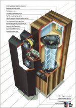
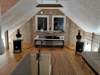
Speakers: Linkwitz LX521.4. Full dipole, 4-way, actively crossed (DSP, IIR)
Source: TIDAL (Masters quality) running on Macbook Pro. 2 channel, 32-bit 768kHz through USB (UAC2)
USB to I2S converter: JLSounds I2SOverUSB with ultra low noise ultra high PSRR power supply (LT3045 based DIY).
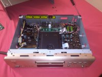
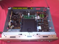
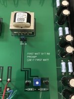
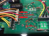
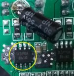
DSP/Crossover/Dac/Preamp: WAF-Audio Najda (slightly modified and with LT3045 based power supplies), fed by the USB to I2s converter. Najda has 4 dual opamps in DAC output stage for eight channels. My current setup uses 4x LME49720HA metal can opamps which I consider to be the most detailed and neutral opamp I have heard. When I want more feeling and life to the sound I switch them to 8x OPA627
Subwoofer amplifier: NAD T975, 4 channels used, one for each woofer driver
Lower mid amplifier: Primare A33.2
Upper mid and tweeter amplifier: Primare A30.5
Other: Power conditioner, DIY based on improved John Risch design


Preparing the equipment and the listening session

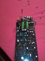
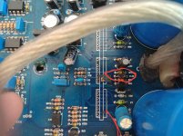
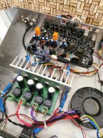
When the opamps arrived, I decided to try if they even fit to my modified Najda board. The board had all the electrolytic capacitors close to the opmaps replaced by Wima MKS film capacitors. I didn’t consider this as an upgrade, by the way. Bursons did not fit the modified board, so I had an good excuse to go back to smaller sized electrolytic capacitors. Replacing them made just enough room to make the Bursons fit.

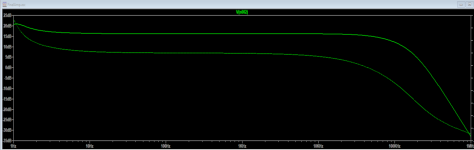
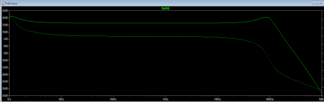
Before listening I burned the opamps in for 92 continuous hours. After that, I fine tuned the speaker positioning based on some in-room measurements using REW (Frequency response, Waterfall and Spectrogram). I also EQ’d some lower room modes. Though, the room still requires more acoustic treatment but I’ll leave that for another day.

Since the Najda requires 4 dual opamps and I only had two Burson V6 classic duals, I listened each track at least twice, once with Bursons on lower frequencies and LME49720HA on high freqs and right after that the second time the other way around. It took me around 30 seconds to switch the opamps safely and restart the song. So, I’m reviewing the low + lower midrange and upper midrange + tweeter separately.


Comparison track by track

Dire straits: Brothers in Arms. Lossless CD quality
This is my all time favourite test song. This is what I first listen to after any change in the setup. I know this song very well.
Mid to high: I immediately got a feeling that the Burson has some micro details missing compared to LME. At the same time I noticed that the sound is somewhat more pleasant, more round and smooth, not as detailed as LME but more life to it. I also noticed the difference in soundstage. Burson seemed to have focus farther away which is generally a good thing but I wasn’t sure this time because at the same time the soundstage width seemed to decrease and the focus was too far away to make a real effect of 3D depth, if it makes any sense. I decided to go for next tracks.
Low to lower mid: Not much difference here but I got a feeling that the extension might be better with Burson. I need another track to confirm.

Tori Amos: '97 Bonnie & Clyde. Lossless CD quality
Mid to high: This closely mic’d track confirms the feelings from the first track. LME was more present and had all the micro details without beeing cold, more on your face in a positive way. Burson was good, a bit warmer but again soundstage was more focused on one point farther away. Still the Burson sounded very pleasant but the micro details were not as clear. It was maybe a bit more pleasant that LME.
Low to mid: There is not lows in this track

Rush: Tom sawyer, Lossless Master Quality
The bass is more real with Burson in this track. Bass kicks better and somehow easier to follow. The margin is really small though.

Stanley Clarke: Tracks #1&2 from album “East River Drive”, Lossless CD quality
With both opamps the bass is superb in these tracks. But the battle here goes again for the Burson. The bass has better kick, it is tight and has bit more authority. Also teh bass imaging and mids are now better with Bursons. Perhaps the LME is bit too detailed here.

ZZ Top, La Grange, Lossless Master Quality
With Buron the bass more pleasant and more present. LME is more lively in soundstage. At the same time the LME is more detailed and maybe too neutral. Burson has more feel and personality to it.


Overall impressions

Even though I was able to pick some differences between the two opamps, the differences are mainly very small and they are both very nice opamps.

With few words, V6 classic is warm, smooth, yet relatively detailed and never harsh. I recommend it. I’m tempted to pair these (on lower frequencies) with the V6 Vivids in the highs.

Overall, Burson was more pleasant in the whole frequency range whereas the soundstage is more focused on one relatively tight spot which is farther away. This makes the feeling that the soundstage is narrower. But don’t get me wrong here, there is width to it but the sounds coming from far left and right are also closer to the listener than the middle, thus, they sound a bit separated from the main soundstage. With LME there is never this feeling, specially with LX521 which are known for making the speakers disappear. This is something I haven’t yet decided which one I prefer, or more so, which was the intention originally in the recording studio. Perhaps this different focus in the soundstage together with the smooth sound character makes the Burson easier to follow and more pleasant and winner overall. Also, I think Burson is more analogue and engaging sounding which is a good thing. LME might be just a bit too neutral in comparison.

These are definitely keepers and will stay in my system for lower frequencies. Now, I’ll have to get me a pair of those Vivids and try them on mid to high frequencies, where I believe those would make a perfect match for the Classics on the lows in this setup. I think the Vivids will give me what I’m missing with the Classic.

In the near future I’ll replace most of the amplifiers with class A amplifiers which I hope will improve the system further. I’ll probably redo this comparison. Also, I’m planning to soon go back to fully analog signal processing, then I’ll compare this setup with fully opamp-less system and let you know the results.

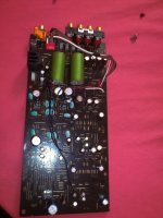
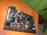
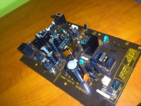
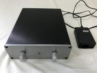
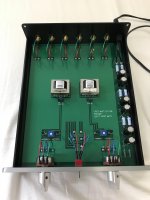
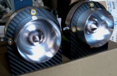
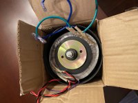
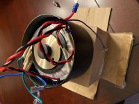
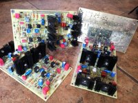
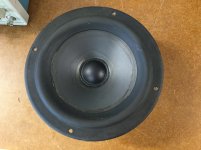
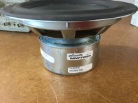
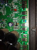
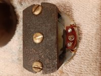
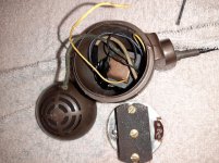
Attached are a couple of photos of the system

Attachments

  • IMG_20200107_191722.jpg
    IMG_20200107_191722.jpg
    340.7 KB · Views: 588
  • IMG_20200106_192923.jpg
    IMG_20200106_192923.jpg
    934.9 KB · Views: 546
  • IMG_20200106_193033.jpg
    IMG_20200106_193033.jpg
    523.8 KB · Views: 534

Jolida 801a Triode Mod

I've gone through my Jolida 801a and feel like I've made some worth while modifications. I swapped out the diodes, coupling capacitors and signal resistors. The last thing I'd like to do to this unit is convert it to triode mode. I've attached the photo below as reference. My understanding is to disconnect the UL tap from pin 4 and solder a 100r - 1k resistor between pin 3 and 4. Can I just depin the wire going to pin 4 (SG1 and SG2) and isolate that from the rest of the unit? Then solder directly to the socket a resistor? If so what watt and value resistor should I consider? Thank you in advance!

Attachments

  • jolida.jpg
    jolida.jpg
    633.1 KB · Views: 299

1.3V DC offset on computer audio output causing severe distortion at low volume

So this problem all started 2 years ago when i first got into electronics and tried building a small transistor amplifier on a breadboard. I accidentally shorted 9V to my computers audio ground connection and then after that day, the audio was distorted badly even at low volumes. There is a 1.3v offset from the L and R channel to GND

I can only get the sound to be listenable again if i take a wire and connect it to another ground point of the computer such as the USB ground, and join it to the audio GND. I have even created a special cable with a USB port and a 3.5mm plug just for connecting the grounds together.

2 years later, i'm trying to fix this by looking for schematics and testing components on the motherboard. The Audio Codec used on motherboard: Realtek ALC262. I could not find the schematics for how it is setup on this my computers motherboard. The only other components with info nearby are diodes DA4 and DA5 which have the label CC5 69 . I cannot find the datasheet for these diodes, but they are 3 pin SMD diodes with two internal diodes.

After some testing i've found out something strange with the diodes
The jack is of the 4 pin type, ( L , R , GND, Mic ) . One diode is connected to the GND pin and the other to the Mic pin. diode DA4 has a seemingly normal 0.7v drop from the middle pin to the right pin and from the left pin to the middle pin. however Diode DA5 has a 0.2v drop instead of the 0.7v drop that DA4 shows.

sadly, i couldn't take any pictures of the motherboard ( terrible camera )

The diode is probably damaged. While the easy fix is to replace the whole motherboard, it costs above $500 USD to do so ( CPU and GPU soldered onto motherboard ). I need to get some help on this matter.

Computer referenced : Dell Inspiron 15 7567

Assistance Request

Hi all,,, I just scored a rather pricey microphone very cheap because he couldn't verify that it work. After moving an internal jumper that allows phantom or battery op. BUT, the on/off is worn & to get it to work, I need to find that sole single spot somewhere between on & off. See my pic of the switch, & the 6 contacts beneath the board. I want to jump some wires to the correct points to have the mic ON, forever. The manufacturer even suggests to leave it on when attached to phantom power, & the rechargeable 9v's will always get a trickle, & never drain. So, can I do what I think is possible? It's a simple 2 way switch, but with those 6 contacts.
Thanks in advance for your assistance.

Attachments

  • 20200827_223306.jpg
    20200827_223306.jpg
    169.8 KB · Views: 122

Another amplifying stage, inspired by Blowtorch

Hello,

I opened this thread to answer questions on the amplifying stage, inspired by Blowtorch. The project was published in Audioxpress, July 2020, pp.44-49. Schematic and PCB files in ExpressPCB format, BOM, gerber files can be downloaded from Audioxpress web site.

I have a couple sets of fully stuffed and tested boards, which I can lend to interested parties for auditioning. You should have 30V bipolar dc supply to power it.

Thank you,
Dimitri

Attachments

  • IMG_5491sm.JPG
    IMG_5491sm.JPG
    406.4 KB · Views: 514

MW7009 Driver for RT5 (RT8)

This driver suffered a magnet shift. It was in a set of Polk RT5s shipped to me without proper packing. I bought a nice replacement driver for the RT5 and set this driver aside. Later, I got ambitious and decided to repair it. The repair turned out reasonably well, but I don’t have a need for it.

I don’t want to oversell this driver. It appears to have been worked on before. You can see the residue from that work on the cone. That work seems fine but I’m not sure why it was undertaken. At any rate, after the repair I installed it in the RT5 cabinet and listened to it for a few days and I can’t tell that it sounds any different from the others.

I paid 60 bucks and shipping for the replacement driver mentioned above. I’m thinking perhaps half that for this one given its history. Mostly, I like to see it go to a good home. As you can see, it’s good enough for the garage speakers but otherwise I’d probably leave the grill.

Check the photos carefully. The adhesive you see is the prior work. I removed the dust cap but I did not separate the cone from the surrounds. The excess epoxy you see around the magnet is intentional as it’s there to help lessen the chance of another magnet shift. In my book that’s considered a good idea on any Polk driver. I used Arleene’s tacky glue for the dust cap and to attach the surround to the basket. Devcon epoxy to reattach the magnet.

Attachments

  • 313D6B0A-F926-4198-BCA9-91BECDB4187A.jpg
    313D6B0A-F926-4198-BCA9-91BECDB4187A.jpg
    806.2 KB · Views: 78
  • 9DF55EC1-2434-4CFA-BFD0-016B045957EC.jpg
    9DF55EC1-2434-4CFA-BFD0-016B045957EC.jpg
    816.3 KB · Views: 95

modifing 6DJ8 kit for DAC output stage

Hi All,


I have a 6DJ8 tube preamplifier kit that I would like to modify to perform as a tube output stage for a AD1862 DAC chip using a passive ressistor for the I/U conversion.
the AD1862 output is 1ma (+/-).
I'll appreciate your suggstions for optimizing the following schematics.


Cheers

Attachments

  • 6DJ8 from Ebay modified.jpg
    6DJ8 from Ebay modified.jpg
    65.9 KB · Views: 363

First DIY mod - Zobel Network on old bookshelf speakers

First off thanks for all the great info on this forum. Work from home gave me the opportunity to get back into the audiophile world but this time not buying my way in (though I did get some nice Schitt gear and a 660s Sennheiser for the home office). I was going to upgrade the speakers for my desk too when I thought about my college speakers in the crawl space, a pair of Infinity RS2000 from the 80s with foam that was dry and brittle. Found out I could refoam the speakers so I got that done, pretty easy fix. The sound was sooo much better than the crappy computer speakers from BestBuy. While doing my refoam recon, came across a Zobel network mod, basically a 4 ohm 10 watt resistor in series with 24uf (22+2.2) caps (in parallel) installed across the terminals on the woofer to improve the bass. I think it zeroes out the high frequency from the woofer voice coil but I'm not 100% sure. Might be the placebo effect but I think it sounds much better, more bass which is what the RS2000 were missing. Next up is a class D amp and a Sex kit from Bottlehead for the holidays. Will need to work in some DIY 3 ways as well. Only flicked hot solder on me once! Stupid 2 size female disconnects on the tweeter, needed reverse polarity on the tweeter and tried to solder them to the terminals...stupid is as stupid does

Dared DV -6C tube rolling

Hi all,
I own a Dared DV-6C that i have done extensive tube rolling on the 12ax7 family, I was looking to experiment with 12hb7/ 6N6P / ECC99but don't know if i will run into problems because of the higher heater current draw.

In annex is the schematics for the circuit if someone can take a look and give an opnion.

The Dared DV-6C review with more schematics
6moons audio reviews: Dared DV-6C

6moons audio reviews: Dared DV-6C
Thanks

Attachments

  • schema_tube_big (1).gif
    schema_tube_big (1).gif
    274.1 KB · Views: 220

A player's ability to Delight the listener

I have all my music, ripped from CDs, on a NAS. As such I can access it from multiple devices. I have one in the garage, bedroom, living room, etc.

The one in the garage is based on a linux box and happens to have "Clementine" for a player. I noticed an option "Play 50 songs at random" so I tried it. Played some stuff I didnt even know I had, albeit in a strange mix!

So if the NAS music collection is simply a database, there must be different ways to access the data in the way you want. Are there players that can do this in a sophisticated way?

If Clementine can play 50 songs at random, how about 50 songs by Miles Davis at random? I didnt see that option...

How about 50 songs released between 1972 and 1976? Turn my NAS held collection into a 70's radio station for a couple hours?

How about 50 songs all in the key of "G". 50 songs with so much bass content? 50 songs with all female vocals? 50 songs recorded in monaural? 50 songs that are instrumentals? 50 songs that were digitally mastered? Play me a set of 50 songs that (insert whatever you can think of)

I realize in the day of Spotify, Tidal, Qobuz, Pandora, Beam_me_up, Scotty, there may be no commercial potential for anyone to create such a player for personal, closed content on a home system. It would only be "nice to have".

On the other hand, why isnt one of my powerful PCs busy figuring out all the different ways it could present the content of my music data base - for all my players to make use of - while it sits there basically doing nothing as I type this? I went through a few of the LMS "categories" - stuff like "jazz rock" which is apparently different than "jazz-rock" and found most of the populated selections to be a joke - as in c'mon, you're kidding me.

Anyone know anything that comes even remotely close to what I'm thinking?

Thanks!

DIY mosfet power amp kits from china

I see several offers from ebay of diy or assembled lits of mosfet power amp pcb.
some looks interesting and i'm questioning about if some of you have tried them.
Here's one:
NEW LJM L15 300W Assembled Amplifier IRFP240 IRFP9240 MOSFET Audio Amplifier DIY | eBay


It's got complementary outputs IRFP240-IRFP9240 is a plus.
Claimed THD is low, but what about reliability and more important sound quality??
There's even some PASS copy of V5 pcb's.
I have a nice beefy power supply and case with big heatsinks.

FS: Analog Crossover Network Basic Kit from DIYAudioStore

I bought this when it first came out, it's still in original packaging. Includes PCB, JFET's and matching resistors.

Analog Crossover Network: Basic Kit – diyAudio Store

It's listed as being out of stock - so there is probably someone out there looking for one.

Asking $49.00 and I'll cover shipping in the US - if you are not in the US, you cover shipping.

Icepower 125ASX BLT Question

This may seem a very stupid question.. but my knowledge is limited and i want to be sure.

I am building two Icepower 125ASX2 amplifiers and I have a question about the wiring in BTL mode figure 17 in the data sheet (see attachments).

Does the little triangle (-1) means that Vin Channel 1 is to be connected to the Negative (3) on the XLR connector (see Attachment).

The longer I look at it the more I doubt, so a conclusive answer would put me out of my misery..

R.

Attachments

  • Figure 17.jpg
    Figure 17.jpg
    21 KB · Views: 371
  • XLR+Connector+Pinout+Diagram+Rear+Pin+2+Hot+v2+green.jpg
    XLR+Connector+Pinout+Diagram+Rear+Pin+2+Hot+v2+green.jpg
    92.4 KB · Views: 375

Amp design critique

Hey folks,

Posting here again, this time asking for specific advice. I'm new to tube amps and have a very fuzzy general education in analog electronics from a couple of decades ago that I never used - mostly digital and software.

I started off trying to make a 12AX7/KT88 hi-fi amplifier a few months back(with a lot of pointers from you guys). I built a prototype on plexiglass and IMO it sounds pretty good. I don't have too many ways to objectively measure its capabilities other than eyeballing sine waves on the oscilloscope. My ears were not offended though.

So after building that and running it off an old iPhone, and then off another device(boombox radio headphone output) with a stronger output signal, I could see that there was room for improvement in terms of overall gain.

That schematic is long gone, especially since I did so many in-flight tweaks on the prototype. I wanted to add another stage and I'm back in LTspice land for a while. The current schematic I know has several flaws, but the old circuit was roughly the same, minus the 12AU7 stage, the 12AX7 stage was biased using an IR LED, and the feedback loop was local around the KT88 and not global.

I have a couple of specific questions, and I'd preferred not to be spoonfed, I genuinely want to thoroughly understand this so I don't keep asking dumb questions.

BC3BcGw.png


1) How should I measure gain with this? I'm using an 8ohm resistor on the secondary of the OT and using the .ac op to get frequency response. The gain measured from that point comes out to a little over 16dB, but this is after a 25:1 volt reduction on the OT. Where would you folks measure this in LTSpice?

2) Speaking of looking at the gain, here is the frequency response as reported by R10(the 8 ohm):
attachment.php

One thing to note is that the rolloff at higher frequencies is only because of C3 on the feedback loop. I feel like this is unnatural and would not work out if this was under a reactive load. Here's the response without C3:
attachment.php

I've found that this roughly 85kHz bump was introduced after the first 12AX7 stage. If I break the feedback loop completely, it goes away, but the frequency response starts to roll off around 18kHz-ish(-3dB) which is no good.

I can alleviate this by increasing the feedback resistor value, but then I run into another problem.

3) I asked this in another thread, how much negative feedback is too much? The problem is that I had a good thing going with my original 12AX7/KT88 design, but I got greedy and wanted just a little bit more gain, because I empirically was able to see it had more headroom without much compromise, and I'm trying to make that a "natural" part of the circuit. Now I have too much gain and I'm using a lot of feedback to keep it from clipping each stage, and it seems this is negatively impacting my frequency response and phase.

Anyway, I would appreciate any pointers on the 3 questions, plus any gentle feedback(but not too gentle) on the design itself. It's still a WIP and I still haven't done a final once over on the math besides biasing and voltage swings yet. Definitely point out any WTFs!!

Thanks folks.

Attachments

  • 6aa.png
    6aa.png
    49 KB · Views: 596
  • 6bb.png
    6bb.png
    30.7 KB · Views: 616

Feedback/noise when sharing power source with amp

I have completed a 19.6v speaker build. Audio quality is great. It has a voltmeter with a built in USB charger.

If I use a bluetooth receiver with independent power connected to the amp audio is great. As soon as I try and power the bluetooth receiver from the same battery that powers the amp, I get very loud static/noise.

I know one answer is separate power supplies, but this is not practical. Is there another was I can prevent this interference when sharing power?

If I use a phone or tablet and power that from the speaker there is no interference. Only when I use a bluetooth adapter (I've tried a couple). I have a pre-amp coming and assume that will also have the same issues when sharing the power supply with the amp.

Pole-Zeros

Could anybody please help to explain me how “pole-zeros” in control theory associated with speaker’s crossover network design? I’ve heard an audio engineer talk about it, though, I could not find an exemplification in speaker application. Would someone kindly lend me a hand for providing an example? Thank you in advance.

Help with TA3020 V2a / V2b boards (connex)

Hello.
I use amps with TA3020 V2a and a V2b boards from connex.
http://connexelectronic.com/wp-content/uploads/2017/08/TA3020_Audio_Amplifier_Module_v2.pdf

I have 2 questions, maybe you can help me.
I mailed connex 10 days ago, but didn´t get an answer.
I have tried it once more today.

1:
I inspected the boards and noticed a burnt C on the underside of the V2a board. I want to replace it. But it is not numbered an not specified in the schematic.
Anybody know the value of this C ?
I attached a picture of the board and the burnt C.


2:
Setting gain factors.
The boards have different gain (V2a has apr. 8dB more gain). I´d like to set them to the same gain.
The manual says "changing the value of the resistorsR16,andR19."

edit:
The manual numbers are wrong.
see my answer #7


Michael

Attachments

  • V2a unten.jpg
    V2a unten.jpg
    519 KB · Views: 120
  • gain.jpg
    gain.jpg
    215.8 KB · Views: 114

Music Hall Trio CD Receiver - SSR Mod.

Hello everyone!

In my livingroom/secondary Stereo set (which I use for Satellite TV & Radio tone, some occational Phono, CD and streaming) I usie a MusicHall Trio (original version, not mk2!). The really cheap Omron relays in this receiver need replacement from time to time which brought me to the idea to use SSRs instead of adapting good but expensive Relays.

The SSRs as such are not between me and success, but the schematic of the Power Output section seems not available anywhere. MusicHall themselves do not cooperate at all. So, if anyone has or knows where to get a schematic, please drop me a private message!

If schematic fails, I'll have to continue reverse engineering the output section which is partially done. Interesting outcome is so far: The Muting function uses a dedicated (Stereo) relay just at the power amp outputs, then loooong PCB traces lead to a speaker terminal board (with a connection cable) which switches two Speaker groups: A/B/A&B. Effectively, for each speaker two Relays' contacts are connected in series! 🙁

I don't understand the rationale behind this, as in my view doing Group switch and Muting could be done with simple logic ICs or even with software: Currently, the sytem control Microcontroller outputs directly connect relay drive Transistors to switch the Relays...

Long story cut short: I want to get rid of the cheapo-Omrons and the weird Mute/Group logic, but would like to verify my ideas with the schematic. So if anyone can help, please PM me.

Thanks and Regards,
Winfried

PS: If there's interest expressed in my project, I'm willing to share here 🙂

Need advise on amp to convert an old docking station

Hi, I'm new to this forum, to be simple I have a Logitech Pure-Fi which is bricked (firmware seems to be bricked) that I want to use as a pc speaker so I decided to find an amp to replace the older board, however I'm a bit exigent because I want :
- Good quality sound, with bass present but not too much, stereo of course
- No white noise when nothing is playing and the device is not off (in idle state)
- Something that works with any 12v DC PSU
- Jack 3.5mm audio input (I have good sound card on my computer, the only issue could be a bad audio cable)
The setup is two 4 ohm speaker in series for each side (so it's like an 8 ohms single speaker for each side) and the older amp was a TDA7491LP, a 5+5w amp, which was enough for me, however it was doing a white noise at idle that was very annoying for me, there is a picture of the setup :
https://cdn.discordapp.com/attachments/330939099752169475/748831360591986728/IMG_20200828_105817.jpg
My goal is to find an amp for 10~15€ (I usually buy thing from ebay or aliexpress), I can solder the thing so I don't care if it's only a kit, I have some 16v 470uF Rubycon caps (if those included are crap), size should not be an issue and that's pretty much it, which amp do you guys recommands me buying ?
(Please don't advise me to replace the whole thing 🙂 )
Thanks you

Some suggestions for my tiny speaker project

Hello all. I'm in the process of making a pair of spherical speakers with size and price as the first priorities.


The enclosure are these tiny balls that picked from a thrift store for 1 euro:
20200820_085219.jpg
Their diameters are around 10cm. My idea is to cut out a small section and mount a full range driver there, eventually having a speaker that looks like an eye-ball :happy1:


With that in mind, I have couple questions and I appreciate your feedback:

  1. What driver do you suggest? I think it should not be anything larger than a 2~2.5 inches. Ideally, I like it to have a rounded edge (unlike e.g., TC7FD00-04 that has a squared frame). But I'm willing to compromise here for better sound quality.
  2. Speaking of sound, I don't thank it makes sense to have a port, or am I wrong? I'm not experience at all and I just have a gut feeling to fill the enclosure with sound dampening material. Any suggestions about the enclosure?
I want to keep this a cheap built and prefer not to pay more than 15 euros-ish per driver.

If it matters, I don't really care about high SPL or laud bass. Instead I prefer to have something flat-ish and a clean response (I have no illusion that such an enclosure and cheap drivers will get me nowhere in terms of sound fidelity. But between the SPL/Laud and flat I prefer the latter...)

Thanks a lot for any feedback.

P.

Denon 2900

Hi all, I have problem with my denon 2900 DVD that play very well on DVD but it does have problem of reading the CD redbook or copy CD or SACD. Where should I start looking at? Any one in here have the schematic for sale? or where should I buy ? should I do some upgrade? like start to change those opamps? remove the caps ? change those diodes?. Thanks for any help in advance.

tube fail: what is the worst thing that can happen?

Hello,
I plan to make my very first tube amp.
I bought two hammond 1609 and a bunch of 6p15/sv83 (as they are very cheap).

The main difference (beside internal wiring) with el84 is that the g2 voltage is "maximum 150V".
Here and there on the interweb I see a lot of people using them exactly like el84, in ultra linear, with the g2 at a higher voltage than the anode (more than 300V). And they didn't complain about something.

So, my question is, what is the worst thing that can happen if a tube really deeply fail ? I guess it can short, and melt the weakest point in the path from B+ to the ground (the transformer primary?)

Would I see the screen glow before failing ?

Quite often, on UL configuration, the screen is connected directly to the transformer, what about using a resistor or a zener to lower the voltage?

I dont mind destroying some few tube experimenting, but I'd love to know how to limit/prevent damages.

Afterward if I am happy with my amp, I'll buy some fancy $15ish proper El84 🙂

Other question, what fails when no load is connected to the secondary of the OT? The secondary becomes a simple inductance and the tension can rise beyond limit? It might destroy the tube or the bypass cathode cap?


Thank you very much 🙂

Denon AVR-3200

Hi all,

I found a Denon AVR-3200 in dumpster, pretty well condition, not tested yet.
I'm looking for the service manual, I want to know whats inside the amp I will probably use it for parts.
Hifiengine has it but I can't download it because new user registration is not currently available.

Any ideas whare to get this manual, for no charge ?

thanks

Too much local negative feedback?

Note: This is more of a general question and not specific to a circuit, so there is no schematic.

Is there a point where there can be too much negative feedback in a stage?

My thinking is that if you had an ECC83 and used one half as a pre-amp stage feeding into the other half as a driver, but the pre-amp stage may have way too much gain for the driver stage to handle. I guess you could technically use a lot of negative feedback to really push it down, to save adding another physical tube, but what is the cost?

The alternative would be to use a lower gain tube for the pre-amp stage like a ECC82, and use reasonable values, but again would require another physical tube.

Any thoughts on this?

First time 3-way active crossover with class D amp boards

Hi everyone,

I want to use class D amplifier boards to build an amplifier to power a pair of DIY 3-way towers using a MiniDSP 4x10HD as an active crossover. I'll be using a Sure 4x100W board for the mid and highs and a Sure 2x 200W board for the bass drivers.

Sure Electronics AA-AB33184 4x100W TDA7498 Class-D Amplifier Board

Sure Electronics AA-AB32281 2x200W Class D Audio Amplifier Board - T-Amp

Can anyone who has done something similar give me some tips? e.g. Should I or can I include a volume knob or just leave that up to the miniDSP?

The manual for the amp board says 'never equip a pre-amplifier to the audio input'. Wouldn't the MiniDSP be functioning as a pre-amp?

Thanks for you help, let me know if I'm in the wrong part of the forum

Dumpster Diving, Yard Sale and Thrift Store Speaker Quick Assessor

I've found many a good speaker at such places - including Tannoys, JBLs, LS3/5As and Klipsch (with blown tweeter in one). None of which I could afford to keep! The ebay prices of those early Pioneer and Sansui 15s!

Yet sometimes I'm reluctant to drag home another piece of junk, particularly if I'm not sure of its functionality. Many times, hunting for a 9V battery and a couple pieces of wire for a "click test" - I've got something better!

Start with a $5 amplifier off ebay;

MP3 USB Flash Drive Micro SD TF Card Player Decoding Amplifier Board Module USA | eBay

...that happens to be able to play .mp3s from a microSD card. Load the card with one of those "15 minutes of pink noise" files. Put that with a portable 5V phone recharger with two 18650 batteries inside from Costco. With a couple of clip leads attached, there's a portable electronic noise source in a zip up case.

By ear. If / when you get good at it, you can tell if something's right simply by listening to the candidate speaker.

If you really want to get technical, there's many an app for your phone which can do the listening for you - and present the results in real time on a nth octave display. I paid $15 for mine, the "spectrum-eye" running on my iPhone 6.

The first graph shown is the amplifier output spectrum, taken using REW with a TASCAM US-122L ADC across an 8 Ohm, non inductive resistor. Not bad for a $5 amp and certainly suitable for initial assessment purposes. The plots in green are the spectrum-eye display, showing how a couple different junk speakers I have laying about sound different. These were measured outdoors.

It's not a stretch to find a pair of KEFs (multiple times...) at some yard sale, wonder if they are OK - and go fetch this thing from the car glovebox. Easy, peasy yay-or-nay data point to help decide. I've seen some sets where the seller was just asking too much, for the risk of trusting a "they work" claim.

Attachments

  • Ebay amplifier.jpg
    Ebay amplifier.jpg
    57.8 KB · Views: 226
  • IMG_1227.PNG
    IMG_1227.PNG
    183.8 KB · Views: 213
  • IMG_1228.PNG
    IMG_1228.PNG
    179.8 KB · Views: 215
  • DSC02526.jpg
    DSC02526.jpg
    655.1 KB · Views: 182

Adcom GFA-555II Bridged Mode

The amp works great in stereo.


Clips at 210 watts both channels driven at 1kHz.


I've been listening to the amp for about a year now. I purchased it non-functioning on ebay. Replaced 3 or 4 transistors (I forget which ones) and the small electrolytic caps. THD is good on both channels. So are DC offset and bias adjustments.


I decided to put it on the bench again and test it in bridged mode.


With the input at about 275 mV and an output of just under 20 watts it begins to clip, see the attachment below.


I haven't started probing thru it yet, because I have some questions.


Can some one point out the signal path in bridged mode? It looks like the only signal going to the right channel is from the left channel feedback. Is that correct?


Doesn't the right channel signal need to be inverted somewhere?


I read thru the service manual but it doesn't describe the operation in bridged mode.


Has anyone come across this before?


Thanks
Gary

Attachments

  • SDS00002.png
    SDS00002.png
    23.7 KB · Views: 118

Head unit choice for Subaru Legacy 2012

So confused with the options available and seller on Aliexpress is not helpful with answering questions. Seeking out on this forum for help with some questions.

Looking for an Android head unit which can support ADAS, CarPlay and Backup Camera.

1. Not sure if this head unit will fit my car. Seller says it will work. Current head unit of my car is attached.
JMCQ T9 8 Cores RDS DSP Car Radio Multimedia Video Player For Subaru Outback 4 Legacy 5 2009 2014 2 din Carplay GPS Navigaion|Car Multimedia Player| - AliExpress

2. If #1 works fine, which option is better? Thought android 9 is better than 8.1, but system offered with 8.1 seems to have better processor/memory.
3a. T9, 8 cores, 4GB RAM, 64GB ROM, Android 8.1, --> $253.22
3b. T3L+, 4 cores, 2GB RAM, 4GB ROM, Android 9 --> $145.86

Attachments

  • Subaru OEM head unit.jpg
    Subaru OEM head unit.jpg
    260 KB · Views: 76
  • T3L with ADAS.png
    T3L with ADAS.png
    682.4 KB · Views: 72
  • T9 with ADAS.png
    T9 with ADAS.png
    703.9 KB · Views: 79

Mosfet Amp resurrection

Currently in the planning stages of my old mosfet amp rebuild.


A couple of questions regarding wiring to the good folk of DiyAudio


Specifically Internal cabling;


Reservoir caps to the output boards ? conductor size ? Twisted, parallel or separated.

Is single core wire better than multi-strand cable ?


Boards to speaker terminals ? conductor size ? Twisted, parallel or separated.
Is single core wire better than multi-strand cable ?


Inputs, sockets to boards ? twisted pair or coax ? Twisted, parallel or separated.
Is single core wire better than multi-strand cable ?


Cheers and thanks in advance


David

Damping factor explained - or not?

I know - the proverbial horse beaten to death. And thought I knew it all.
Yet, when trying to explain it in simple terms I found I didn't know enough detail to do that 😉

Most explanations come up with an example of a kick-drum pulse that all of a sudden stops, and the speaker which continues to move, unless 'braked' by the low internal impedance of the driving amp. In moving, the speaker generates EMF that has to be absorbed by the amp. The lower the output impedance of the amp, the better it is at braking the speaker (plus a few other issues but this is the gist of it). So far so good.

But then I thought: the speaker generates EMF because the coil moves in a magnetic field. So I would expect the speaker to generate EMF continuously and not just when the kick-drum stops!

That leads to a realization (I think) that when you fix the speaker moving part and stop it from moving, the amp sees a different impedance then in normal operation. So the amp damping and speaker EMF generation is a continuous process and not just with impulsive signals.

Am I correct?

Jan

Through the floor manifold question

To best keep peace in the house, I need to move my subwoofer into the basement and have it fire back up into the living room from whence it came. Rather than have one large vent, I am looking at making the manifold into a ‘U’ shape and the exits will be through two smaller vents along the wall under the television. The vents would be separated by one floor joist bay that houses an HVAC duct and from what I can see two vents will help cancel nodes due to the sound emanating from two separate locations.

The bottom of the ‘U’ is where the driver will mount. I like to tinker and try different types of subs, so the driver mount will be somewhat universal. The opening will be large (19” x 14”) and there will be 4 large bolt studs so that, with a simple adapter plate, pretty much any speaker/enclosure combination (<= 15” driver) can be bolted to it – sealed, ported, infinite baffle, etc.

My question is this… Since the path lengths of the vents are in the 22”-24” range, would I be running into a 140Hz peaking issue? Or would this be easily taken care of with the crossover? I am not sure how prominent the peak will be.

Any help would be greatly appreciated.

Attachments

  • Basement_Manifold2.jpg
    Basement_Manifold2.jpg
    95.9 KB · Views: 241

Rockford Fosgate 800a2 repair

I'm looking to repair a RF 800a2 amp with one catastrophically blown channel. I believe the other channel is still working (it's been a while since I tested it & I will confirm soon). I'm reading dead shorts across all output FET outside legs on the right channel. If I'm remembering correctly and the other channel still works properly, is it safe to assume the power supply section is fine and I only need to focus on the output section of the blown channel?

I've been reading other repair threads here gathering information (and being impressed by Perry Babin's knowledge & generous willingness to help). I haven't pulled any of the FETs or source resistors yet, but from previous threads I've put together a parts list of what I see being needed so far. I'd like to know if these parts have the correct specs for the typical parts needing replaced. I've done other smaller repairs on these amps, but this is the worst one I've attempted so far.

Attached are some pictures of the board and my current parts list. The quantities listed are for multiple reasons - trying to get matching date code FETs, price break cost, and for potential future use in other amps.

Attachments

  • parts.jpg
    parts.jpg
    192.6 KB · Views: 295
  • image001.jpg
    image001.jpg
    542.2 KB · Views: 282
  • image002.jpg
    image002.jpg
    421.6 KB · Views: 260
  • image003.jpg
    image003.jpg
    582.3 KB · Views: 270

Most powerful amp for 20v

Hello everyone,

This has probably already been discussed at length but I don't feel like I can clearly get the answer.

I'm building a DIY boom box from MDF and vinyl. It's designed to be a bluetooth and USB speaker utilising my JBL GT608C component car speakers left over from another project. Ultra compact - the main drivers are to be in sealed compartments about 1.2 litres each. I cut the parts from MDF using a water jet cutter at my workplace.

These speakers are rated at 210W peak, 70W RMS per speaker, 4 ohm.

I thought I'd be tricky and power the thing with a cheap eBay single DIN head unit. So I bought one of these
1DIN Car Stereo Radio Bluetooth Handsfree SD/USB/AUX/FM Head Unit MP3 Player AU | eBay

However I wired it up very roughly to one speaker to test and the speaker sounded really woeful and barely any power. I guess the head unit's power output isn't much. The chip seems to be a Toshiba 2969HQ which is apparently 47w x4 but I don't think the circuit is up to much, there are barely any components on its board.

So my question is, would I be best to use a tpa3116d2 Bluetooth board or similar? Ideally I'd like enough power to get the best out of those speakers. Would a tpa3116d2 be plenty (at 18v supply) or maybe dual tda7293?
TPA3116D2 120Wx2 Wireless Bluetooth 4.0 Audio Receiver Digital Amplifier Boa DH | eBay
Durable Dual Channel Stereo 2.0 Audio TDA7293 DIY Metal HIFI Amplifier Board Set | eBay
The tda7293 seems very powerful but I'm hoping to run it from my Ozito drill batteries which are 18v 2.0ah (I have three of them), would powering the tda7293 be too much of a headache? Would they even be much more powerful than tpa3116d2's at the same supply power? Or would I be better to get a basic brand name single din head unit (much more expensive)?

F5 Turbo v2 Stereo Amp Illustrated Build (my first amp build)

OK. This has been a long time coming. I joined in 2013 and planned to get on to building shortly thereafter. But then I moved around the world a couple of times, a few different cities, and even more houses within the cities. Throw in a couple of kids and a couple of renovations and 2020 rolls around. Even then, it took an international pandemic to give me time to do the build.


Firstly, I want to thank everyone on this forum for the questions, answers and photos. I have read extensively, learned a lot and there;s still more to learn - and build. Thanks to everyone who has answered my questions as well.


In particular, I want to thank 6L6 for taking the time to talk to me (I think that was in 2014 when I was in NYC) and also for your illustrated build guides. With this guide I am following your lead and hope that this can give back to some other new diyers. So thanks Jim.


Also many thanks to Nelson Pass for providing the designs and articles for the amps, and being an avid supporter of diy. It is very much appreciated.


----


This thread is a work in progress. I will add photos and words and edit them over time. Today (23 August 2020) is the "first draft" if you will. I will try to bring in what I have learned from lots of different threads and add notes on things I found useful especially from someone who had no electronic/lab equipment at all.


On to the build....(see next post)

  • Locked
Loud buzzing on Ferguson 3020/Garrard 3000 Vintage Record Player

Hi,

When I turn this 1960's (?) Record Deck on, it gives a loud buzzing noise over the speakers. It increases with volume. I can plug my phone into the radio jack (and play music), and play a record on the deck, and the sound comes out, but there's always the loud buzzing noise.

I've got the speed changer, and turntable etc to work, and would like to get it cleaned up and fully working, as it could look lovely. However I don't have the electronic ability to fault find it. I do have the ability to use a multi-meter and do the odd bit of soldering etc, so would like to "have a go".

Does anyone think if I change the capacitors in the attached photos I may stand a chance of curing the buzzing noise? I don't want to throw a lot of money at it, or sub it out to someone (and have to pay them), and if it stands a decent chance, I'd like to give it a try.

I'm going to also put a copy of this post in the transistor amplifier section, as there may be a lot of experience there too.

Thanks, Rob

Attachments

  • DSC04160.jpg
    DSC04160.jpg
    571.7 KB · Views: 80
  • DSC04161.jpg
    DSC04161.jpg
    644.6 KB · Views: 83
  • DSC04163.jpg
    DSC04163.jpg
    570.9 KB · Views: 89
  • DSC04164.jpg
    DSC04164.jpg
    558.8 KB · Views: 74
  • DSC04165.jpg
    DSC04165.jpg
    731.3 KB · Views: 89
  • DSC04166.jpg
    DSC04166.jpg
    740.4 KB · Views: 59

The barbeque....

Well the barbeque is on full production..
The valve amp is thrashing bass lines out...booze flowing oh yes..
About time..the sun is out...Oh yessss about time..😀
Thought the weather would never change..what happened to the hot summer nights.....
Stuff it ...I'm going to buy a motor bike and go to the isle of mann for the TT..its been far to long..😀

Regards
M. Gregg

Elementary question about B+ semantics in articles

I read tube amp project articles in my down time, and have always had this little hole in my knowledge as a newbie. These articles will often describe the power supply after describing the amp circuit, usually with a separate PS schematic...

In the PS description If I see the author say something like... "You'll need a 270-0-270 transformer and with this filter circuit your B+ should come to about 315 volts"... If no other info is given... Should I assume the 315 volts number pertains to the power supply measured completely unloaded, or should I routinely make the assumption that I will have 315 volts after the supply is hooked up to the amp? In this case the amp schematic didn't have an explicit B+ value named on it, class A. Similarly when I see an amp schematic that names 250 volts as the B+, this means I have to design the PS to supply 250 volts at max expected load correct? So a supply that measures 250 with no load would not be appropriate, I'd have to make sure my supply settles at 250 with the max load, correct?

Seeking guidance for LCD projector

My apologies if I end up asking a lot of redundant information, I'm reading through the stickies and other posts on the forum but wanted to specific guidance areas.

My intended application is business presentations. I do contract work designing human/machine interface systems (HMI) and as part of that work I have to showcase the system as a design it. The problem I'm increasingly encountering is that they want the system designed at 1920x1080 but when I go to present it their projectors at nowhere near that resolution.

The projectors I've seen on the market can easily run up to 1000+ dollars. I just need a professional looking display at HD resolutions in classroom type rooms (I should be no further than 10-20 ft from the surface I'm projecting onto)

I've chosen a lot of the equipment I plan to use.

For the screen I've picked the B101UAN01.7 10.1" 1920x1080 typical response time of 25ms and supports 16.7 M colors.

I've chosen an appropriate LCD driver module for it (the T.VST29.03)

I'm planning on using a 100w LED (with heatsink and driver) as the light source.

I've downloaded the focal calc program and have gotten a basic idea for the distance between each component, however I'm still at a loss on several key points.

1. What's the difference between a split fresnel and unsplit fresnel? I've read the google explanation, but how do I know what I'm dealing with when it comes time to purchase it?

2. What are the basic guidelines for Fresnel size? I've seen it should be "slightly" bigger than my lcd display, but is there a more precise guideline?

3. What color light is best for my light source? I was leaning towards warm white.

4. What sort of guidelines should I look when it comes to the triplet focus lens?

5. The distance to the projection surface will vary from location to location, do I need to do anything special to compensate for that fluctuation, or will the triplet lens allow for that kind of focusing?

Thank you in advanced for any assistance you can provide!

GB for EU: 8 pieces matched Toshiba 2sk170 BL grade Jfet’s

TL,DR: 10 new Slots - each with 8 matched 2sk170 BL Jfets - price 50 Euros per set plus 6 - 15 Euro shipping - price went up due to big amount of work with matching those fets and bad calculation of the first 15 Slots


ALL old SLOTS GONE: Total 15 Slots – each with 8 matched 2sk170 BL Jfets - price 40 Euros per set plus cost of shipping

Hello,

inspired by the GB that was rocked by diyaudio user JeffreyJuice, I want to run my own group buy for matched octets of original 2sk170 Jfets.

I will buy the stuff from the same reliable source that Jeff used for his group buy. It is one of the last known sources for original Toshiba 2sk170 parts in the whole wide world. Buying in the US does come with some downsides. I will have to pay import tax and customs. Thats why the cost for a tight matched set of 8 transistors will be 40 Euros, plus shipping.

As I am located in Germany, shipping costs will be cheaper if you live in the EU rather then the US. I want to avoid shipping overseas (US, NZ, AU) but I will do if you ask me and pay the actual cost of shipping to your country. Shipping to Germany will be around 5 Euros, most other countries in europe 10 Euros. Please ask for shipping costs to your country.

I will buy an unopened bag of 200 transistors and match them for Idss and Vp using the following method:

Greatly+Improved+JFET+Matcher+II.png


I use to sort the values using a spreadsheet to get the best possible sets of matched jfets. I have some experience with this method and I know that it will produce reliable results.

When all 15 slots are gone I will ask you for payment. When 10 slots are paid for, I will order the bag of transistors. It will take some 10 to 14 days for them to reach me and another free weekend for me to match them. After matching, all orders will be shipped as soon as possible.

You will get 2sk170 from the BL Range – so Idss could vary between 6 mA and 12 mA. But if you give me a hint which Idss range you need I will try to solve it.

I hope I did not made any mistakes here and that no forum rule is violated by my post. Please PM if there is any problem. Or if you just want to participate in my GB.

s-l1600.jpg

Old Microphone Question

Good evening all,,, Pardon for posting this on another DIY Forum, but wasn't sure where to go,,,but this cool mic came with an old Webster Electronics amp, & look what I see when I open the capsule,,, diaphragm & internals seems to be all there, but the 2 wires coming from the small tranny, are disconnected from the 2 solder joints at that wafer beneath the magnet. How would I determine which wire goes where? I s'pose one way would be is to wire it & see if it's OOP with another known 'correct' mic,,, but is there any other telltale sign from before my time?
Thanks all & be well
Kenny

Attachments

  • 20200825_203858.jpg
    20200825_203858.jpg
    970.4 KB · Views: 152
  • 20200825_203816.jpg
    20200825_203816.jpg
    1,022.7 KB · Views: 145

What is the best way to replay mono LP on a stereo system?

I have a handful of mono LPs in my collection, too few to justify a dedicated mono cartridge or listen with only a single channel active. My phono stage does not have a mono input. Assuming normal listening to dual channels, I can think of a few ways to configure the phono stage input:

1. Stereo cartridge outputs to to dual phono input (normal stereo).
2. L or R cartridge output identically to dual phono input (single channel mono)
3. L+R summed cartridge outputs to dual phono input.

I have only used option 1 and the drawback is very audible. The occasional surface noises/pops/clicks can appear to be in the L or R output and are a distraction when all the signal is meant to be dead centre. The vertical out of phase component can cause a spread to the central image. With option 2 the vertical component will appear mixed with the mono central signal. With option 3 the vertical component should be cancelled, assuming perfect gain and phase matching of L, R channels. What are the opinions on the pros and cons of these options and are there any others I have overlooked?

Need Help Designing Smaller Version of Apollo-7 MTM Center Channel

I'd like to upgrade my center channel for my home TV/Theater setup.

I have about 8" of space just below the TV for the center channel (it's a built-in cabinet, so I can't simply move the TV up higher).

The Apollo-7 MTM by DIYSoundGroup looks awesome , and I've built a few kits from them already. But it's a 10" tall speaker box. So I was thinking I could create a very similar setup, but with the Anarchy 5.5" speakers.

What I'd love to know is:
1. Does this seem like a good solution?
2. How do I figure out the box size?
3. Could I use the same crossover as provided for the 7" drivers?

Thanks in advance! I've been having a blast getting into DIY speaker building, but designing my own box is definitely going to be a first.
Projects by fanatics, for fanatics
Get answers and advice for everyone wanting to learn the art of audio.
Join the Community
507,829
Members
7,889,954
Messages

Filter

Forum Statistics

Threads
406,328
Messages
7,889,954
Members
507,829
Latest member
Apfelbau