Hello,
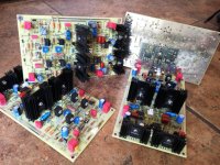
I opened this thread to answer questions on the amplifying stage, inspired by Blowtorch. The project was published in Audioxpress, July 2020, pp.44-49. Schematic and PCB files in ExpressPCB format, BOM, gerber files can be downloaded from Audioxpress web site.
I have a couple sets of fully stuffed and tested boards, which I can lend to interested parties for auditioning. You should have 30V bipolar dc supply to power it.
Thank you,
Dimitri
Attachments
you can simplify the servos and cut the number of opamps by having out- control just points A and B, and out+ controlling points C and D.
Hi Dimitri
i would like to Audition it - what should do to get it for audition/ return- do you want me send you a PM?
thanks
Kannan
i would like to Audition it - what should do to get it for audition/ return- do you want me send you a PM?
thanks
Kannan
Hans, thank you
Kevin, I concur, I'm using two opamps per balanced stage for other projects
Kannan, please send me PM
Kevin, I concur, I'm using two opamps per balanced stage for other projects
Kannan, please send me PM
Dimitri,
Many thanks for sharing.
Did you perform any simulations before building and testing ?
Cheers,
Patrick
Many thanks for sharing.
Did you perform any simulations before building and testing ?
Cheers,
Patrick
No, I didn't do any simulations for this project.Did you perform any simulations before building and testing ?
When there is large difference (>0.5V) between input voltage and voltage across capacitor, then diode is conducting and capacitor (dis)charges through resistor.
When the voltage difference is small diode is not conducting and effectively disconnects resistor from capacitor. Capacitor holds the charge.
This is conventional technique for condenser/electret microphone input stage.
When the voltage difference is small diode is not conducting and effectively disconnects resistor from capacitor. Capacitor holds the charge.
This is conventional technique for condenser/electret microphone input stage.
When there is large difference (>0.5V) between input voltage and voltage across capacitor, then diode is conducting and capacitor (dis)charges through resistor.
When the voltage difference is small diode is not conducting and effectively disconnects resistor from capacitor. Capacitor holds the charge.
This is conventional technique for condenser/electret microphone input stage.
Thanks, nice tip! I love these practical things I've never seen in common literature..
Btw about "cap multiplier" you're using mosfet/bjt, why not just irf610 type mosfet, or darlington connection instead? All the variations have similar performance, is it about the sound?
Cheers, Borko.
Member
Joined 2009
Paid Member
mosfet has high input impedance, bjt provides best transconductance as a follower and if needed it can be used with lower voltage drop. Higher transconductance means better sound. Mosfet conductance is less of an issue at high current.
mosfet has high input impedance, bjt provides best transconductance as a follower and if needed it can be used with lower voltage drop. Higher transconductance means better sound. Mosfet conductance is less of an issue at high current.
Ok, I know that part, as i remember from the simulation, PSRR of cap mul. varieties is fairly similar, that's why I asked. Never tried to compare different cap. multipliers with low psrr gain stage, I guess there could be a difference..
That is correct. BJT also has a base current, which makes a voltage drop on RC filter resistor. Resistor value should be not too high for low voltage drop/power dissipation on transistor. For the desired time constant filter capacitor value should be high enough.bjt provides best transconductance as a follower and if needed it can be used with lower voltage drop
That is correct. BJT also has a base current, which makes a voltage drop on RC filter resistor. Resistor value should be not too high for low voltage drop/power dissipation on transistor. For the desired time constant filter capacitor value should be high enough.
That's all correct, but just checked in MicroCap, there is almost no difference between IRF610 or darlington BC546/BD140 as serial pass devices in the same type of cap.mult., darlington only needs 47K instead of 100K in the RC for the base current. In the simulation, you get (in both cases) about - 65dB PSRR and less than 0.8 ohms output impeance with alo similar bandwidth etc..
Do you think it's up to models?
Last edited:
Also Vgs of small mosfet used + Vbe of bjt is very similar to Vgs of a single IRF610, so I still don`t see, why extra parts..
Never mind I was thinking that this specific configuration was used for "sound properties" 🙂
Never mind I was thinking that this specific configuration was used for "sound properties" 🙂
Did you put something like 400 Ohm as a load in simulation?
What if you will place ac source in series with load and measure the voltage on the output (output impedance)?
What if you will place ac source in series with load and measure the voltage on the output (output impedance)?
- Home
- Source & Line
- Analog Line Level
- Another amplifying stage, inspired by Blowtorch