120Hz hum in my amp, and here is a scope picture.

I am trying to find the source of the 120Hz buzz coming out of my speakers. At least I think it is 120. Anyhow I disconnected all input to the amp and connected the end of the speaker cable to one of the inputs to the scope. The other input to the scope has a 120Hz from a signal generator. Be aware that I am a total newbie to this and I don't really know what I am seeing on the scope from the amp. I expected a much cleaner picture.
So, am I going about this in the correct manner ?
If not, which is likely, please guide me.

Attachments

  • IMG_0855.JPG.jpg
    IMG_0855.JPG.jpg
    72.6 KB · Views: 527

TL subwoofer - vent on diff surface from driver?

I'm planning a TL subwoofer on a napkin, so just doodling.
I've noticed that most TL subs seem to have their vent existing on the same surface as the driver, generally just below it, but Im wondering whether this is absolutely essential?
What I want to do is fit the 15-inch driver to the front of a tallish box, near to the bottom so it is roughly at one-third of the line distance (at S1/S2) and the vent would then exit out of the base, so to speak (so the sub would need to be raised up on feet).
Alternatively, if i flipped it, the driver would be near the top of the front surface facing the listener and the vent would exit out the top towards the ceiling.

Or does this mess up the 'merging' of the front and rear waves?
On first principles, I'd expect no problem with such a design but what do I know?

No sound Yamaha CD-S700 to DacMagic 100

I'm curious about the digital output (optical & coaxial) from a Yamaha CD-S700 as when hooked up to a Cambridge Audio DacMagic 100, there is no sound even though the correct sample rate lights up on the DAC indicating a locked signal. There is a direct mode on the CD-S700 that turns off the display and digital outputs and have that turned off but have tried both ways. There's no clues in the service manual and there's no menu in the player to play around with settings.

I did read a user on a Dutch site had a similar issue but there was no answer to his question.

The CD-S700 does digital output to my Yamaha AVR with no issues and all other equipment such as TV, CD players, DVD and BD work with the DacMagic 100.

The DAC will not be used with this CD player as was installed for other equipment but has me very curious as I thought digital outputs either optical or coaxial would be standardised.

Attachments

  • CDS700_Dout.jpg
    CDS700_Dout.jpg
    40.6 KB · Views: 322

Help me work out a solution for these mid tops

Hi there,

I'm relatively new to the world of pro audio. I've built a pair of subs and a pair of kick bins that I absolutely love, but I've been using a pretty ratty pair of Eons as the mid tops. I wanted to change that, and threw together a pair of cabinets using the extra birch I had from the kicks and subs. I've attached an image to give you an idea of what they'll eventually look like.

Each cabinet will contain two Eminence Delta 10A speakers sharing the same enclosure volume of almost exactly one cubic foot (and a compression driver/horn in a separate chamber above). I got a great Ebay deal on these four drivers with the intent of building something comparable to the "Small Vented Cab" described by Eminence here (except with two drivers and roughly twice the enclosure volume): https://www.parts-express.com/pedocs/more-info/290-412--eminence-delta-10a-cabinet-design.pdf

My dilemma is that I can't find anywhere sane to put the two 3" ports! My only real solution would be to mount them in the back of the trapezoid, but I've read that ports shouldn't be behind drivers if you can help it. I've also looked at using up to four 2.5" ports on the baffle, but the length of these would be very short to maintain the 95hz tuning frequency of the box I'm going for, and I've read that air velocity is a concern.

One thing worth noting is that I'm designing these to be high passed at 200hz--I think having them play down to 125hz as is possible in the linked Eminence cabinet design might be nice if I need it (say if I were to pair it with just my subs instead of my subs + kick bins).

Sadly, I don't have a windows machine so I can't get WinISD. I'm hoping someone could kindly help me with modeling port air velocity with the four 2.5" (or even four 2") ports (maintaining a 95hz tuning frequency for the 1 cubic foot box) to see if it's untenable at any point 200hz or above.

Alternatively--since the two deltas will be used chiefly for midrange (and not being able to go down to 125hz wouldn't really be a dealbreaker)--should I consider just leaving their enclosure sealed with a volume of 1 cubic foot? I've seen something similar done in this plan, here: Speakerplans.com

If someone is able to model excursion and frequency response in particular, that would be amazing. I'd also love to hear any general opinions regarding vented vs sealed enclosures for PA midrange.

I'm really thrilled to be building speakers and will be certain to keep this community apprised of my progress!

Attachments

  • rBWC2o5OTfaj70gjBM5OCA.jpg
    rBWC2o5OTfaj70gjBM5OCA.jpg
    1,008.5 KB · Views: 223

Memphis Audio 16-ST500D protection curcuit help.

I repaired the power supply and 2 shorted irf640's on this memphis amplifier. However something is still damaged. Regulated is +-15, the power supply runs smoothly without the rectifiers. With the rectifiers in curcuit the amplifier flashes in and out of protection, the amplifiers draws about 2.5amps of current then not. Its fast the ammeter just swings as it attempts to power up. I could use some help identifying the problem in this protection curcuit.

Attachments

  • 16012357575212244078443883246476.jpg
    16012357575212244078443883246476.jpg
    1 MB · Views: 131
  • 16012357936691862112750237872792.jpg
    16012357936691862112750237872792.jpg
    1,007.7 KB · Views: 110

Elekit 8200 DX in Triode Mode

I’ve had my 8200 DX for a few months and have loved every minute of it. I kept the amp in ultralinear mode since I first plugged it in and loved the sound. I decided to try triode mode this weekend, which is accomplished by cracking the case and moving a small jumper for each channel. Wow! The sound got even better, at least to my ears. I’ve read that amps using triodes tend to have a gorgeous mid-range but a less taut low end. That has been my experience as well with the 8200DX, but the bass sounds quite defined and satisfying all the same. Piano and horns, though, sound like they are in the room with me. The whole sound of my albums is fuller and richer. Maybe I’ll switch back to ultralinear mode in the future, but right now, I am loving how my albums are sounding.

Capacitor doubt

hi all,

I have this amp with shorted output transistors for one channel.
There is a capacitor that connecting rca input positive signal to the secondary ground via a resiator. The designation on the board shows as it is ceramic disk type capacitor but I found 10uf 16v caps. I found those caps burst for two channels. Others two values gone too low. I expecting if somebody had interfered with them or I dont know if it is factory itself. Attaching image of C301 and C401.
Please suggest what to use.

Attachments

  • 20200929_081953.jpg
    20200929_081953.jpg
    740.7 KB · Views: 126
  • 20200929_083033.jpg
    20200929_083033.jpg
    561 KB · Views: 122

share your experience on sound of hybrid amps

I've seen some interesting hybrid amps about but very little information on how they sound. I'd like to get a bit of a feel for how different approaches to hybrid amps have on the sound.

By hybrid I don't mean some sand somewhere in amongst the glass (such as a CCS plate load) - but something more substantial such as SS gain stage feeding tube output via OPT, or tube gain stage feeding SS output buffer.

Thanks.

TL431 as CCS for phase inverters or cathode resistor.

I was designing a part of my power supply when I was running trough the datasheet and the basic application notes of the TL431 and I found two images that particularly interested me.

One is a "precision shunt regulator" and the other one is a "precision current limiter".

Firs I want to talk about the current limiter. its essentially a really good constant current source or sink when you use it that way. Its a two wire contraption and it fits perfectly into old tube amplifiers as a CCS to directly replace a resistor because its a two wire device. Doesnt need any power to power a op amp none of that nonsense.
I know its not as easy a a depletion mosfet cascode or a speciffic component meant for CCS. Most of the CCS components are limited with minimum current 8mA and the voltage and so on. (the IXS something something part number if you look in its datasheet more in depth the limmitation is there. Doesn't mean it wont work but its not ideal or bordeline stable)
This could basically work with practically anything. the TL431 is not dependant on the voltage across the entire device so you dont fry it not even if you were to put 600V across it because all the work would have been done in the transistor(dont take this literary because it does not work below 2.5V and some current to open the transistor so there is a lower limit to this). You can put this in the anode or the cathode of any tube. You just need to do some little math to figure the resistor values and voila got your 100% accurate current source / sink.

The second image is the shunt regulator. This one interested me because of a other topic here on the forum where we discussed instabillity caused by drifting bias on the cathode resistor at high loads. I realised we can use the 431 as a shunt regulator so we can set the bias of the tubes on a cathode biased amplifier just like we would in a fixed bias enviroment.
Trained eyes that know something about the 431 would relise that even a EL34 amp like the mullard 5-20 would exceed the voltage capabillity of the 431 (I found the bias voltage on 470R resistors with mine at 450V B+ to be 35-37V and the 431 is maxed in 33). Simple solution put a 15V zener between the 431s anode and the base of the transistor now you got the voltage range extended by the zener voltage so you can even run larger tubes like this. Even KT88s.
And this would be best of all also a drop in two wire replacement for a regular old cathode resistor.
(in the schematic replace the input resistor with a power tubes cathode and VI as the vacuum tubes anode voltage and there you go now you have a rather precise bias that should never fail.) Its like putting zeners in the cathodes but better because you can infinitely adjust it in a certain range. Also the curve of this contraption should be A LOT SHARPER than that of a regular old zener. For stabillity reasons I would leave in the cathode bypass capacitors or replace it with something a lot lower cappacity and something that will never ever go bad (1uF MLCC cappacitor and yes you can get these SMD caps in this capacity at quite the voltage ratings or a film 1uF capacitor, maybe even a SMD tantulum would be okay. It wouldnt be stressed so much anyways.)

All sounds ideal so Ill make this real in full SMD except the power transistor for the shunt regulator. The CCS even at 10mA in a phase inverter (lets say 120V on the cathodes is just 1,2W so I can easily get away with a D2PAK and some heatsinking pads.

Attachments

  • 1_QBmZLDzmlGGc9IgpKhqamw.png
    1_QBmZLDzmlGGc9IgpKhqamw.png
    54.8 KB · Views: 437
  • 4024.tl431.JPG-550x0.jpg
    4024.tl431.JPG-550x0.jpg
    18.2 KB · Views: 449

Nomex 164 -My DIY experience on a 2.5 way

Hi Happy Xmas to all members.
This is my first experience building a 2.5 way based on Nomex 164 designed by Troel using Peerless HDS midwoofer renamed now Tymphany 830875 and ex Peerless HDS tweeter 810921 now remaned Scanspeak D2608 91300.
In the past I have experienced only 3 ways with 10 in woofer. So I will probably have to tune my ears to bass coming from 6.5 driver asnd hope I shall not be disappointed.

First project - FAST / WAW like

Hello all,


I am considering a FAST-like speaker with :

  • Full range Fostex FE126En
  • Woofer Monacor SPH-220HQ in 30 litres sealed enclosure
  • Monacor SAM-300D plate amp for the woofer
I would like to reach down to 40Hz.

I am afraid that would be misusing the woofer, because when simulating it (WinISD) in a sealed 38 litres I hit xmax with only 15W (out of 100W admissible) with 100dB SPL. Further more, the SAM-300D includes a 3dB bass boost at 40Hz, which adds a little excursion, reducing admissible power.

Is that a design flaw ?
Is the 100dB SPL too low ? I suppose that is RMS value, so what margin does it leave in terms of crest factor headroom, could I actually play music at 100dBrms SPL ?

I don't particularly play music loud, I just want to avoid an undersized system (FWIW the room is about 5m x 5m 3m ceiling, open into a 2nd room the same size, open into a third).

Thanks for your advice and input.

Tang Band W6-1914SB as a Fullrange?

What do we know about the W6-1914SB? I ran across this 6in honeycomb diaphragm neodymium motor midrange today. I looked at the response curve and it seems wide and flat and with decent sensitivity. I think it won’t make much bass but could be a good top for a FAST/WAW.

attachment.php


attachment.php


attachment.php


Code:
Resonant Frequency (Fs)70 Hz
DC Resistance (Re)6.5 ohms
Voice Coil Inductance (Le)0.073 mH
Mechanical Q (Qms)7.19
Electromagnetic Q (Qes)0.37
Total Q (Qts)0.35
Compliance Equivalent Volume (Vas)0.39 ft.³
Mechanical Compliance of Suspension (Cms)0.399 mm/N
BL Product (BL)10.23 Tm
Diaphragm Mass Inc. Airload (Mms)13.97g
Maximum Linear Excursion (Xmax)0.5 mm
Surface Area of Cone (Sd)140 cm²

Data sheet:
https://www.parts-express.com/pedocs/specs/264-905--tang-band-w6-1914sb-spec-sheet.pdf

Overview X-XA-XS-Power Amp Series - Elcaps using both in large and small Outline-why?

In power amplifiers of this series are to find two kind of electrolytic capacitors behind the rectifier :

A. Large can versions with screw terminals and low-ESR e. g.
FTcap (F&T) GMB 47310075145 (Ø 75mm x 145mm, ESR = 3-4 mΩ)
%product-title% kaufen
or similar like Mallory, Cornell-Dublier or Sprague
NOS Mallory 10,000UF 75VDC CGS103U075V3C Electrolytic Can Capacitor.
https://static6.arrow.com/aropdfcon...f45da10ee14f2ad1ac33/3632267624208725550c.pdf
Sprague 36DE213G050BB2A 21000uF 50V Aluminum Electrolytic Capacitor: Amazon.com: Industrial & Scientific

The following models use this kind of capacitor
1) X-150 (not X-150.5)
2) X-350, X-350.5, X-350.8
3) X-600, X-600.5
4) X-1000 (from X-series first amplifier ever)
5) XS-150 (two devices /each channel due to outdoor power supply)

B. Small versions (mounting type "Snap-In") with high capacity in large quantity e. g.
Panasonic ECO-S1HP103CA (Ø 25mm x 50mm, ESR = 36/27 mΩ)
Blocked
or similar:
Nichicon LLS1K472MELA/LLS1J682MELA/LGU1H682MELA/LGU1J472MELA
https://uk.rs-online.com/web/p/aluminium-capacitors/8526298/
https://eu.mouser.com/ProductDetail/Nichicon/LLS1J682MELA?qs=CTiUoleKpMEAuBr9VqiAJg==
https://uk.rs-online.com/web/p/aluminium-capacitors/1671486/
https://uk.rs-online.com/web/p/aluminium-capacitors/8466962/
EPCOS B41252A8478M000
https://uk.rs-online.com/web/p/aluminium-capacitors/7714721/
Vishay (formerly BC) MAL225631682E3
https://uk.rs-online.com/web/p/aluminium-capacitors/1730638/
KEMET (formerly BHC-Aerovox) ALC70A472BD063
https://mt.rsdelivers.com/product/k...μf-electrolytic-capacitor-63v-dc-snap/1813462

The following models use this kind of capacitor - at least according the top view images without cover:
1) X-150.5 (not X-150)
2) X-250, X-250.5, X-250.8
3) XA-25
4) XA-30.5, XA-30.8
5) XA-100.5
6) XA-200, XA-200.5

The great advantage of using large can versions are lowest ESR, very reliable and very long life time 10000-15000 hours) so as best possible sound results in all respects.
Disadvantage here is high space requirement and very high costs, even when considering volume discounts.

The great advantage of using small versions is very low cost and the very little need of space required with a very high total value of capacity. Disadvantage here is the short life time around 2000-4000 hours -at least according the datasheets and poor dynamic behavior in listening tests compared to bulky and space-consuming capacitors with screw terminals.

And now my questions:
1) What is it based on, when to use the small (Ø 25mm) caps (small cv product) and when to use the large capacitor cans with screw terminals?
2) When buying X-XA-XS power amp devices in used condition, it is better to prefer the ones with screw terminated can electrolytic cap versions ?

Thank you very much for an advice.
In the attachment images from X-150 and X-150.5

Attachments

  • X-150.jpg
    X-150.jpg
    174 KB · Views: 408
  • X-150-III.jpg
    X-150-III.jpg
    130.4 KB · Views: 387
  • X-150-II.jpg
    X-150-II.jpg
    203.7 KB · Views: 397
  • X-150.5-1405051382467592935.jpg
    X-150.5-1405051382467592935.jpg
    178.3 KB · Views: 383
  • X-150.5 1405051383840670566.jpg
    X-150.5 1405051383840670566.jpg
    172.2 KB · Views: 374
  • X-150.5-1405051382507977113.jpg
    X-150.5-1405051382507977113.jpg
    214.5 KB · Views: 175
  • X-150.5-1405051383909817040.jpg
    X-150.5-1405051383909817040.jpg
    184.4 KB · Views: 189
  • X-150.5.jpg
    X-150.5.jpg
    79.5 KB · Views: 191

Hammer Dynamics Super 12, Full Range Speaker Kit

--- Hammer Dynamics Super 12 Speaker NOS speaker -- KIT -- for sale asking $599.00 - A great Full Range Speaker KIT!

-- 97 db Speaker - works well with Tube or Solid state

--Full Range Driver

--Small coaxial mounted Tweeter

-- Kit actually cost -- $ 1,260.00 in it's final year .

http://www.audioheritage.org/vbulletin/attachment.php?attachmentid=32729&stc=1&d=1212251296

Denon PMA 1060 cuts out at quarter volume

Hi all,

First time poster here. I just recently bought a Denon PMA 1060 stereo amplifier which has an issue. The audio will cut out at about quarter volume. The actual volume varies slightly with different music (louder music will cut out at a lower volume, quieter music will cut out at slightly higher volume). I have to power cycle the amp to restore audio but if I go too loud again, it will cut out.

I'm guessing the protection circuit has kicked in but don't know why.

I've checked for stray strands of speaker wire, but I use banana plugs and don't see any stray wires.
I have tried left and right channels connected by themselves, with no change.
I have tried the second (B) set of speaker terminals, no difference.

The speakers connected are Aaron ATS4, rated at 160W at 6 ohm so should be able to handle the power. The amplifier I replaced but is still working doesn't cut out with these speakers at quite loud volume.

I do have a multimeter, but am not strong with amplifiers or analog electronics. I've measured the voltage across the speaker terminals and there does not appear to be a big DC offset voltage on the terminals. I've found a service manual online and there is a procedure to adjust the idle current, but I don't think that would cause this issue, would it? From what I've read, too high idle current makes the amp run hot, and too low affects sound quality. I don't think either of this is happening in this case.

I'm wondering if anyone knows what the issue might be? I can take it to a repair shop who seem confident on what the problem is, but wondering if it's a cheap and/or common fix, or more complex!

Thanks in advance.

Anyone using a car audio amp in a home stereo set-up?

Hi ! sorry if i jump in but i really need some advice on car audio amps.
First of all i have absolutely no experience with car audio.
I do not listen when i drive for safety reasons (the music distracts me a lot).
Anyway ... i see many car audio amps around ... new and used.
So i thought about using one of them as a power amp in my stereo system.
I have already bought this to power it ...

LEDMO 12V 20A Alimentatore Interruttore AC 110/240V to DC Trasformatore di Alimentazione 240W: Amazon.it: Fai da te

One thing that i like very much is the gain control that can be found on i guess all car audio amp. I have a preamp with a high gain and that attenuator could be very useful for me.
So the question is ... what to buy ? i really need only 20-30 Watt/channel but with good current
Any advice and suggestion would be very welcomed and appreciated.
Kind regards, gino

Parasound HCA 1000A Bias

Hello, I'm fairly new to the world of solid state amps, more of a tube guitar amp guy. A buddy brought me a Parasound HCA1000A which needed new filter caps. The amp seems to be working fine now but I would like to verify that the bias is correct. My understanding is that the bias calculation/adjustment procedure is to measure voltage across output transistor emitter resistors then use ohms law to drive current and adjust for 30-40 mA. So I'm measuring voltage on the
0.33 ohm emitter resistors on the big 2SC3519 and 2SA1386 transistors but I measure 0V on all of them. Is there something I'm doing wrong?

J.

Attachments

Wavecore MTM project (after lockdown)

This project is going to take a long time, but I've given it a huge amount of thought, on and off for the past few years. I've designed many a theoretical possibility with Visaton drivers, but even though they're very good, and I've had really good experience with them, I want to give something else a try. Something with maybe slightly lower Q, I don't know. But what I do know is that I want to base the speakers on < 6" drivers. I can't seem to find properties I like of the W130S, and I don't like the FR or price of the Visaton aluminum drivers.


I want to keep with the MTM I've enjoyed so much. I've looked at many drivers, and I really like the CSS 7", but for MTM, they're a little big, and they're > 6" anyway. So it was a choice between Wavecor 4 3/4 paper drivers and 5 3/4 glass fiber drivers. The 4 3/4 paper cone has a dip in the FR between 1 and 2 kHz, and that won't do for me. So after all that, I've decided to design with:


MTM

Wavecore WF146WA06
Peerless DX25TG59-04


Does anyone know, firstly, anything about the Wavecor drivers, and whether they're any good (especially for $80 each), and then more importantly, that Peerless tweeter? I like the FR because the tweeter crossover will usually level it off nicely. I want to make it a 50L vented box.


I'm thinking of crossing over at 2 kHz, but I'll figure out the exacy frequency when I've had more time to see how far spaced the drivers will be.

Parasound HCA-2200 flatening sinewave at ~10W

I'm working on a Parasound HCA-2200 (MKI). It is flattening the bottom of the sinewave in both channels at the same time, around 10W.

I've recapped the unit, except for the main filter caps. Someone had done a partial recap before. They had added an electrolytic cap across D105/106 and 205/206. I pulled it and didn't note the value. Probably should have. Not sure if it was supposed to be there and they had botched the wiring of replacement RCA jacks so I wasn't confident in their work. And was trying to fix a buzz (which was because I still hadn't gotten the RCA jacks wired right). Could it have been there for this reason? EDIT: looking at pictures in another thread where the caps are there. Guess I screwed up not keeping track of them. Anyone know what value they might be? I could email parasound again I guess. EDIT #3: In the MKII schematic it looks like there is 1uF capacitance here.

Where should I start looking?

Are the two trimpots at the input offset settings? If so how do I set them since there is two? EDIT AGAIN: Post #7 answers (Parasound HCA-2200 problem - need some help)

Schematic attached. Only the MKII schematic was online so I emailed parasound and they sent the MKI schematic.

Attachments

Leave it on

I've heard from many that leaving on your electronics isn't always bad and sometimes it might be in your advantage.
More specifically in solid state amps the burst of power during the power on period can cause more Harm than the "fatigue" components might experience when having electricity flowing through them all the time. You also don't have to wait for them to heat up for the best performance.
Is this true in your opinion? I get that class d are also very efficient so you aren't even waiting a lot of power but what about class a-ab?

Marantz PM7200 repair: lacks power?

Allô everyone, thanks for this forum and your attention.

This Marantz PM7200 cuts out the sound on both channels for a half a second on transients, and recovers. Until the next transient.
It will do it as well on not very dynamic music with volume pushed, at the slightest peak.

It does that on any source. It does it running in class A. It does it with "source direct" selected (no bass/treble controls). With that Tone Board in function, cutting the bass lessens the problem.

So my first thought was: lack of power reserves, so, bad capacitors?

(Amp draining test tune: Schonherz & Scott "wishing well" on Windham Hill https://www.youtube.com/watch?v=BAwxJg7mEr8)

And it also does it on headphones (Sennheiser HD518, 50ohms), no speakers fed. Which is a big relief as it takes the lovable Elipson 1303 out of the equation.

No hum, no relay clicks when sound cuts, no thumps from speakers, no hiss, no distortion.

As for distortion, i hear a certain "granularity", but i usually evaluate sound quality wearing headphones, and that headphone test was done playing a .mp3 from a Samsung phone...

(((
(i moved the Marantz to the bench to sneak inside. Replaced it (only to hear the Linux Pc used to stream live Radio-Canada 'cause we can't afford the Cable/Satellite Scam) with given to me STK powered Pioneer VSX515. Please everyone use that as last resort. It's awfull...even without headphones)
)))

...so i don't rely on that. Add to that that i don't hear much above 10Khz.

As for relay clicks, i can hear a couple relays clicking on power up sequence, but the speaker relays clicks are very faint. Maybe these click when the sound cut happens and i don't hear them. Anyways the sound always resumes after .5second without cycling Power, until the next transient.

On speaker out (without speakers plugged, no input, Vol at Min) i measured -2mv DC on R, -20mv on L. Same in class A. I did not do the other measurement (quiescent current?) yet, i need probe clips for those hard to reach test points.

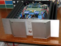
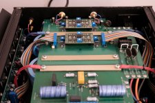
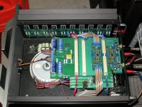
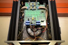
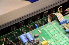
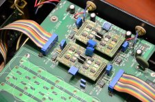
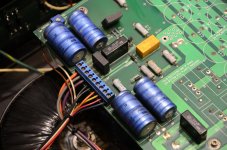
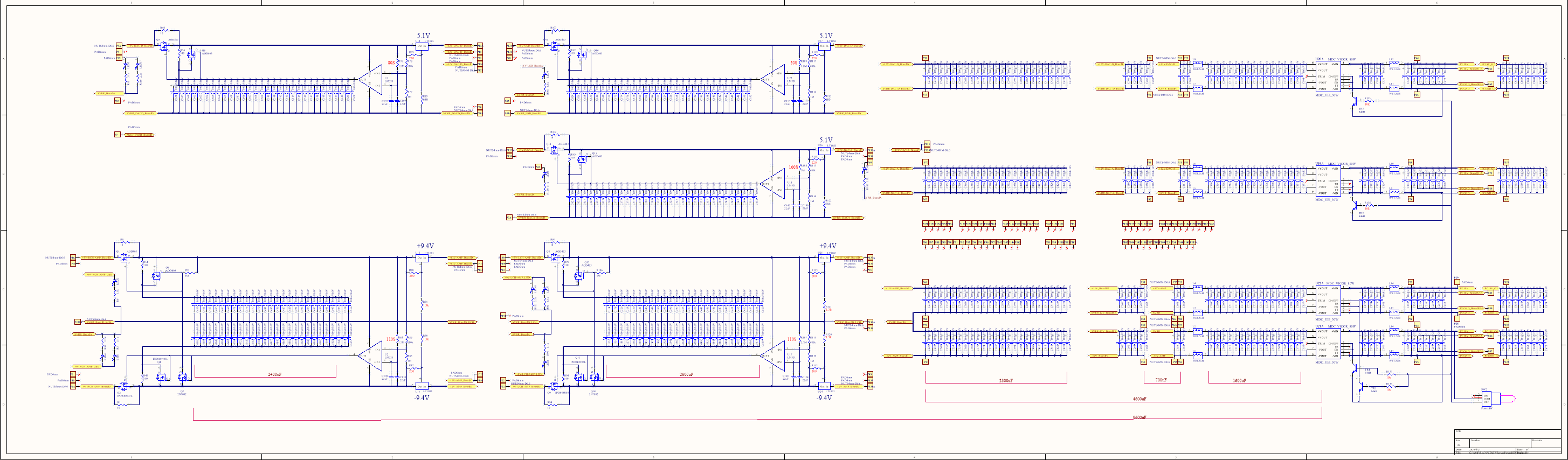
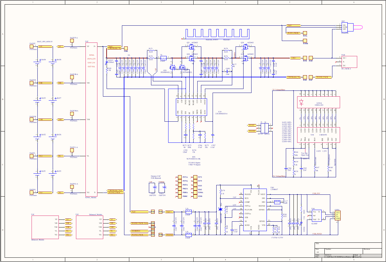
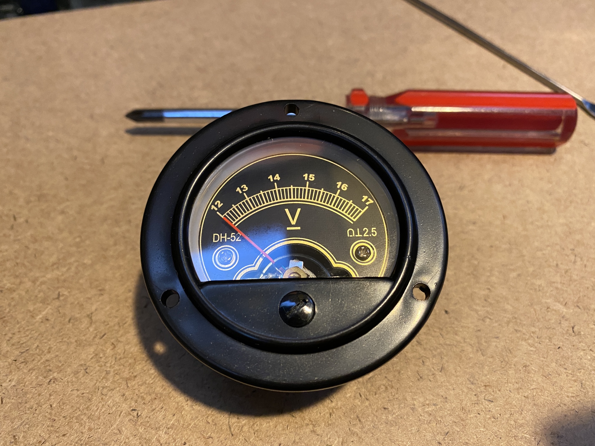
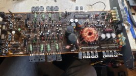
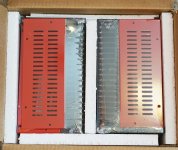
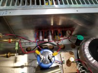
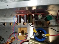
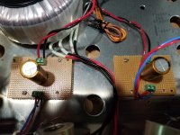
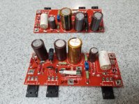
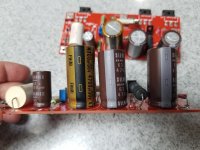
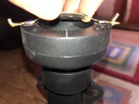
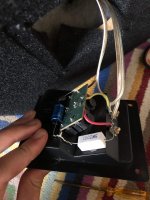
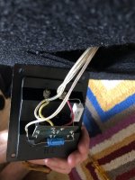
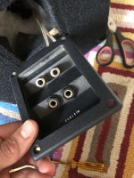
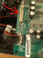
On visual inspection (no dismantling, though) i didn't see any burns, bad traces, or bulging or obviously leaking caps. I only saw 2 suspect electrolytic capacitors, with whitish powder nearby on the board or on top. #2203 and #2204 (470mF and 2002mF) on the Tone Board.

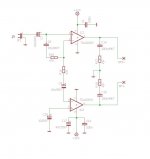
And i was surprised to see on the schematic (if i'm reading right) that AC (what voltage??) is fed to that ToneBoard, direct from the main transfo, going through 4 rectifier diodes and to those 2 caps. So i wonder if they can be involved (if bad) and how, as the sound cut happens even with that ToneBoard out of the signal path (source direct).

That fault developped and got worse with time. It was not there when i first used the amp (bought used, 2-3?? years ago). Which makes me hope that some weakness was already present whaen i first played it, for i immediately missed my precedent music companion HarmanKardon PM660. The Marantz lacked the "Ooumph" (what a nicely eloquent audiophile term ;-) ). I was even more sorry when i played a vinyl on it, but i now know i can correct that wrong capacitance on the input, thanx to knowledgable inhabitants of these forums (fora? fori? forae? pardon my poor Latin).

I should also mention that i seldom put the marantz on Standby, it was On 24/7 :headbash: <slapping own fingers>.

I researched bad capacitors (i now know how to discharge before testing, for one thing) and sound cutting and related stuff for a week. Apart from surface mount, i can manage a soldering iron (i remember replacing diff pairs on the HK, the Marantz will be a joy to work in) and multimeter and basic safety measures (grrr, i need probe clips), so throw it at me ;-)

Sorry for the verbose precision, i think i told you all i observed.

And thank you all for your insights and help.

service manual:
https://www.hifiengine.com/hfe_downloads/index.php?marantz/marantz_pm7200_service.pdf

Need a lot of help please.

Hi I am new to this community and plan to build my first pair of speakers soon and just need a ton of help. This build will most likely be 1 of 2 build I want to do, both will be 3 way builds without crossovers. My plan is to get a hivi 3.1 kit to practice on with the dsp, learning what I can then build my second pair with what I learned. Kinda feel stupid asking these questions but at this point I am desperate to learn and try!

Q1: How are crossover less or dsp speakers wired? Do they still need internal circuits?
Q2: How do you match speakers in a 3 way build.
Q3: what determines how much power goes to each speaker.
Any links, advice or book recommendations are welcomed.

Thanks in advance.
Akil.

3.5mm AUX to stereo speakers

This question is way to complicated for me to try to Google so I thought I'd try here.

I'm making a DIY Bluetooth speaker from woofers, an amp, and a Bluetooth card. The audio goes from my phone to Bluetooth card, to amp then to speakers. However, the only way to connect the bluetooth card to the amp is over 3.5mm AUX, and I'm struggling to figure out how to do this.

On the bletooth card there are 2 positive and negative ports (origionally sdesigned to go straight to speakers, but there going to an amp first now bevase the speakers are bigger.)

So does anyone have any suggestions on how to wire a set of stereo speakers to an AUX port? This AUX port was a solution to another problem someone here solved for me so I think it should be possible. Thank you in advance. (Also the amp will be here tomorrow so I'd like to get started)

Not So Fearless (or, How I Learned to Love the Fan)

Mr Pass often talks of "fearless amplifier builders". I have to admit, I am not quite so fearless. Maybe it is my naturally cautious nature, I don't know....

I built a pair of F5 Turbo monoblocks with a couple extra output drivers to handle the crazy loads from my ESLs, and it runs warm. The temp gauge shows 50degC at idle, and up to 60degC when driven. For my own peace of mind, if nothing else, I would prefer to to run a tad cooler.

I have seen a thread before where someone put a fan in the middle of a board and set his amp onto it. Sounded like a good idea, so I did the same. I hated the fan noise. That was much worse than the uneasiness of hot amps. But it did work really well.

So, to reduce fan noise, I took three approaches:

1) find a really quiet fan to begin with. There are some very good ones that have feathered back edges on their blades and good engineering that are very quiet. This helped greatly, but not enough.

2) I made a simple fan controller using a Cypress PSoC running a fuzzy logic algorithm that varied fan speed by temperature. The lower the speed, the lower the fan noise. Basically a simple thermostat with a few different fan speeds based on temperature and whether the temp was rising or falling. This was almost enough. The fan noise was very much reduced. But, like most engineers with a problem on their mind, that was still not quite what I wanted.

3) When fans beat against the air, the blades create an air vibration (noise) based on fan speed, number of blades, etc. This is generally a single frequency plus some harmonics. To counteract this, I added a pseudo-random speed delta to the speed controller. This spread the fan noise out over a range of frequencies. I have not verified this yet, but I believe the total noise to be the same (area under the curve) but the greatest amplitude is very much reduced. Even on the highest speed, I have to be within a couple of feet of the fan to hear it.

With these three in place, from my listening position, I am unable to hear the fan, even when the music is silent. And, the amp now runs at 40-45deg, a level I am much more able to live with.

Attachments

  • inuse1.jpg
    inuse1.jpg
    470 KB · Views: 359
  • inuse2.jpg
    inuse2.jpg
    290.8 KB · Views: 355
  • topview.jpg
    topview.jpg
    769.6 KB · Views: 359
  • cutting1.jpg
    cutting1.jpg
    574.7 KB · Views: 350
  • cutting2.jpg
    cutting2.jpg
    840.1 KB · Views: 350
  • gluing.jpg
    gluing.jpg
    392.9 KB · Views: 193
  • routing.jpg
    routing.jpg
    419 KB · Views: 204
  • faninstall.jpg
    faninstall.jpg
    603.3 KB · Views: 211

My first amp!

I didn't expect this to be so fun!

I came across this article about a really simple class A follower, by Greg Szekeres:

https://web.archive.org/web/2002061...com/projects/showproj.php?file=szeke1_prj.htm

Having gotten some electronics experience lately (I took the contextualelectronics.com course about using KiCAD to design PCBs), I decided to whip one up, Manhattan style, just for kicks.

Surprisingly, it worked!

Before constructing, I did throw it into LTSpice just to be sure the mosfet and resistors wouldn't get too hot.

The FETs are just 2N7000's.

The input caps are Kemet 1uF film caps.

The output caps are 330uF OS-Cons (this was a guess, I had no idea if they sound any good, I just guessed they'd be better than stock electrolytics due to better ESR).

The regulator is a 7809, with a 100uF electrolytic on the input and on the output. I was tempted to go with a fancier output cap for the regulator, but if you go too low with the ESR I've read you can cause oscillation in these simple, old regulators.

First I tested with 100 ohm R4 (the FET bias resistors), but everything was barely warm to the touch so I stepped up to 47 ohms, and that seems fine.

Producing a working result on my first try is very encouraging, but there's a lot more I feel I need to learn. For example, I only know enough LTSPice to simulate current levels and heat levels. What do people use to simulate what the actual THD will be?

Also, I was surprised I couldn't find much material on single-ended class A FET headphone amps which use small FETs (e.g. TO-92 package). I'm sure there are FETs which sound better or worse than the 2N7000, but I had trouble finding info like that. Again, I'm assuming that if I had some sort of software which had the IV curves for these FETs, I could simulate and find the THD?

Attachments

  • photo (4).JPG
    photo (4).JPG
    129.6 KB · Views: 563
  • Screen Shot 2014-06-15 at 8.56.55 PM.png
    Screen Shot 2014-06-15 at 8.56.55 PM.png
    122.5 KB · Views: 545
  • szeke2.gif
    szeke2.gif
    6 KB · Views: 547

Philips GA222 - replaced power switch and platter spins at warp speed

My turntable has been in storage for decades, but it worked perfectly when I stored it. Unfortunately it spent time in an attic that gets hot, so I'm thinking something might have been affected by the heat. I followed a tip I found online for replacing the poorly-designed original power switch with one from a computer. The two power leads went to the top terminals, the brown transformer lead to the bottom left, and the blue transformer lead to the bottom right. The new switch worked perfectly, but when I start her up, the platter spins like a washer on spin cycle. Anyone have any ideas how I might troubleshoot this? I don't even know where to start.

FS: Matched pr type 45 triodes

Hello all.
Up for your consideration.

Super Silvertone Type 45 vacuum tubes matched and guaranteed AS NOS

This is the actual heading from the Ebay listing that I purchased these. These were purchased from a respected established Ebay dealer.

I paid $ 150.00 for the pair. Will take $ 25.00 off and sell for $ 125.00/pr.

I cannot post pics on this site. Send me your e-mail via PM and I will send pics and detailed pertinent data directly to you.

Here's the deal. For US buyers, shipping on you. I'll cover insurance.
International buyers, shipping and insurance on you. Please understand that I will only ship internationally if it can be insured, which leaves out the cheaper USPS method. Also I will not lie on a customs form.

This price is good for PayPal Friends and Family payment only. If no FF then PayPal fees will be added.

Thanks for looking and be safe

Cheers, Crazy Bill

Crossover ??'s on Prosound 2 Way

So I have a SoundTech 2 way 15" woofer with horn loaded compression driver tweeter. Looking at the crossover looks like it's not optimal to me. Treble is soft with a simple 1st order crossover at around 7-8Khz that I can tell. It uses a 2.2uF series cap in tweeter circuit. Tweeter is 8ohm. Also has a 16ohm padding resistor across tweeter. So am I miscalculating the crossover point and shouldn't it be more like 2-4 Khz?

Toroidal Transformer VA and Capacitance required for LJM 20.5 amplifier board?

Hello,

I am looking to build a dual mono amplifier with a pair of LJM 20.5 amplifier boards,

2 PCS L20.5 Ultra low distortion 0.0015% Power amplifer board KTB817 KTD104 200W|Amplifier| - AliExpress

and I am wondering what value VA toroidal transformer (35V-0-35V) I should use?

I was going to use a transformer from Parts Express,

toroidal 35V+35V - Parts Express Ships Fast and Ships Free.

My best guess is that 250VA per side should be fine for this amplifier at this voltage.

Next question, What overall capacitance value at what voltage do you think this amplifier requires?

These are the boards I am looking at,

A pair of these,

2PCS L15D/L20D/L25D and L/MX50 Series mono rectifier power supply board With speakers DC protection board|board|board boardboard power supply - AliExpress

or,

LJM 8 X 63V 2200UF Power Supply Board DIY PSU kit for Power Amplifier|kit supply|kit kitskit diy - AliExpress

I'm thinking the first board at 63 volts should be fine.

If you have a suggestion on a single power supply board and transformer VA value, please leave a reply as I am not married to the dual mono plan.

Thoughts, comments, suggestions?

Thank you,

David.

Need TV7 data setting for EC88/6DL4 (Not ECC88/6DJ8)

Hi,
New member here. Just a quick thread to see if any members had TV7 tube testers. I specifically need the data setting for a TV7 for a EC88/6DL4/6522/8255/E88C triode tube. The EC88/DL4 is not related in any way to a ECC88/6DJ8. I just acquired a quad of these made in the early 1960's by Amperex and they need to be tested. I've downloaded all the addendum updates for the TV7 series including Nolan Lee's and this tube is not listed in any of the documentation under all 5 of these tube type designations.
Would greatly appreciate any members feedback,
thank you in advance!
jim

FS: Unbuilt Amp Camp V1.0 Kit with Red/Black chassis

For Sale : Unbuilt DIYAUDIO store original V1.0 Amp Camp Kit with beautiful Black Red Chassis. This is a complete Kit with PCB/Components/Hardware and Power Supply - photos show one but the other one is also included in this sale. You can modify the kit to match the present Version higher output and it will require different power supply

Picture of the kit for sale. Prefer US sale as it is easier to ship but willig to ship world wide. PM me for price / shipping etc. I spent 296 USD and expect that as a base price plus shipping/paypal fee

Attachments

  • DSC01733 (2).jpg
    DSC01733 (2).jpg
    701.1 KB · Views: 377
  • DSC01734 (2).jpg
    DSC01734 (2).jpg
    628.5 KB · Views: 377
  • DSC01735 (2).jpg
    DSC01735 (2).jpg
    686.5 KB · Views: 350
  • DSC01736 (2).JPG
    DSC01736 (2).JPG
    921.6 KB · Views: 340
  • DSC01737 (2).jpg
    DSC01737 (2).jpg
    1 MB · Views: 354

Bi-amped Acoustat

I just spent a while re-building 4 sets of interface for my 2+2's.
I went through all the mods I've seen here, the C-mod, a high voltage 0.22uf across the zener string, different values of final output resistor, from 100M to 500M.
The original design was just about spot on, all the latest "mods" dont really do much, give it a bit more tizzle if anything, which some will interpret as detail.
Even the original design with the 220uF crossover cap is pretty good, ( replacing the 220uF with a new piece brings it back to life, maybe the tales of it being necessary to replace with polyprop cap aren't exactly true)
A refurbished interface is about as good as you will get, whether its the old 220Uf design or the C-mod with 47uF polyprop.

BUT, there is a way to get a drastic improvement in clarity, open-ness, bass tightness and all round musicality, although in theory it shouldn't work.
Separating the inputs to bass and HF transformers, ie, providing two sets of speaker connectors and using two sets of amps, one for bass transformer and one for HF transformer, really makes the Acoustat a superb loudspeaker (which it already is, but now its even better.)

Now I know that the two transformers get blended at the HV section feeding the panels, and I agree that bi-amping shouldn't make any difference, but it surely does, and I just cant listen to the single amped version now.

I'm using very powerful amps, so I dont think its just a matter of doubling up with power, maybe it is, but whatever, if you get a chance to try this its very worthwhile.

But having said that, I have enormous respect for the original design and dont want to infer that there is anything wrong with it.

For me, bi-amping is the ultimate way to listen to Acoustats, despite my brain saying it shouldn't be so.

TDA 2003 bridged schematic, any comments?

Hi guys.. welcome comments, remarks, suggestions or criticism of the wiring diagram for TDA 2003 chip amp in bridged mode. I am not the author, just a long time ago, I redrawn the wiring diagram on a piece of paper, the author was of German origin ..the wiring diagram was published in the magazine Hobbielektronika / if my memory serves me right /...

Attachments

  • TDA 2003 bridged schematic.JPG
    TDA 2003 bridged schematic.JPG
    35 KB · Views: 146

UDIO-8 with Audiolense getting started routing, speaker check connections.

I know this is niche but I am hoping a few people might have experience with the UDIO-8 with Audiolense. So far I have set the UDIO-8 in ASIO4ALL as playback device and my external sound card/microphone as recording device. And then chosen ASIO4ALL in Audiolense as both playback device and recording device. And no sound in check speaker connections. I have also enabled output channel override.

I have the PC>UDIO-8>two separate DAC's one for high frequency and the other for low> into two separate amps > woofer and compression driver

All to no avail, just can't seem to get any pink noise for the speaker check connections. Any ideas?

I can't imagine it being different from a multichannel DAC.

Help with dsp bass

Hello, sorry if my english is bad. I have build a boombox with a minidsp 2x4 and 4 Tpa3116 is really loud but im triying to upgrade this with a ADAU1701 because i want to use Superbass algorythm and a compressor for bass when the volume is high but i dont know how to implement it in sigmastudio, i'll use the minidsp for crossover and parametric EQ so the ADAU will be between the bluetooth module and the minidsp.

Can you help me with the schematics?
Thank you.


This is one video of my boombox but with the old midwoofers from car audio, now he has 3 Lavoce wsn102-00-8-ohm 10-inch Prueba de sonido altavoz Proyecto Integrado - YouTube
I hope you like it.

Attachments

  • WhatsApp Image 2020-09-27 at 19.55.28.jpeg
    WhatsApp Image 2020-09-27 at 19.55.28.jpeg
    173.2 KB · Views: 81

FS: Power Follower 2014 Populated PCBs

For sale are two working Power Follower 2014 amplifier PCBs.
Requires 30v to 42v DC, rectifier bridges and small reservoir capacitor.
Installed are Nichicon, Mundorf and Elna Slimic II caps. By-pass caps not included. Reservoir cap PCB included. Will include 18v protection diodes currently not installed.

Selling because I have 3 other power followers amplifiers and need the case for a large amp build. It is a very good sounding amp, which takes its sound cues from which ever high-gain preamp is in front of it.

More information here: the Power Folllower

Asking $50US, plus paypal and shipping.

Thanks for looking,

Vince

Attachments

  • PF2014_00.jpg
    PF2014_00.jpg
    473.9 KB · Views: 149
  • PF2014_01.jpg
    PF2014_01.jpg
    242.1 KB · Views: 155
  • PF2014_02.jpg
    PF2014_02.jpg
    215.1 KB · Views: 154
  • PF2014_03.jpg
    PF2014_03.jpg
    259.6 KB · Views: 137
  • PF2014_04.jpg
    PF2014_04.jpg
    265.7 KB · Views: 149
  • PF2014_05.jpg
    PF2014_05.jpg
    192.9 KB · Views: 105
  • PF2014_06.jpg
    PF2014_06.jpg
    213 KB · Views: 85

Tpa3116 + CSR8635 EQ/DSP Settings

Hello,
This is Sreenath, And been a member here for a long time. Hope you all are fine.
Actually I am facing a problem where I bought this TPA3116 Bluetooth Amp with CSR8635 on it, & after I had it installed for my speakers i thought why not I adjust the EQ/DSP to sound perfect.

But, now for some reason I tried to run the PS Tool & Rom Configurator for it and it worked without a problem. But for Some reason the Parameter Manager is not Working.

I tried the CSR8635 ROM Series A03 UFE(CVC) on Win 10 & 7 32bit and it showed this error - The algorithm connected to USB SPI (1003432) identifies itself as E00C @ 44100 Hz, for which there is no available support.

If anyone reads this post please help me get a appropriate Parameter Manager to Control the DSP of CSR8635.

Attachments

  • 61OyB9vr6-L.jpg
    61OyB9vr6-L.jpg
    68.5 KB · Views: 206

Frugel Horns with Foster FE163 drivers

Hey Folks,
I am going to be building a set of frugal horns for these drivers. I have been in touch with Dave D. and he has a set of plans for them. I'll be getting them soon. I will keep this thread updated as I go along with pics and questions.

For now I do have a few questions. My limited reading has me suspecting these will be some really good horns with the exception very high and very low roll off. The low I think I can deal with using a good sub and filters. However, I am not sure of the highs. First, does anyone have a guess asto what frequency I should look at for roll off? 8K, 10K, 12K, ???? Next what spl would be a good level to mate to the horn, 95db/spl/watt? Lastly, Dave reccomended a horn tweeter as best suited to match the horn. Any reccomendations?

My drivers are rated at 5w RMS or 10 peak, so power is not an issue. I will likely run these with an el84 pp tube amp - capable of 5-7 watts RMS clean power.

Thoughts anyone?
mark

PRP PR9372 0.1% resistor kit for Twisted Pear Ivy III

Hello All...

I'm planning on ordering 0.1% 1/4 watt 50 PPM PRP 9372 resistors for the TPA Ivy III. Normally this tolerance is not stocked by anyone and the price prohibits ordering one or two sets. Each set will include the following resistors with a cost of $45 plus shipping with a 4 week lead time. I need only 5 people to do it. If more join the price should drop if we get 16 or more. Just reply to this thread if your interested.

750R Qty 4 .25W 0.1% Precision Metal Film
390R Qty 8 .25W 0.1% Precision Metal Film
180R Qty 4 .25W 0.1% Precision Metal Film
2K2 Qty 12 .25W 0.1% Precision Metal Film

Thanks

My DIY BT5.0 headphone amplifier

Hi everyone

I'm Murasame Yui

My full time job is high power LEV/EV battery PCB designer
Also DIY is my hobby.
So i design a battery wireless amplifier myself.

All the circuit and mechanical and PCB are design by me.

I only build one and will never mass production.
because it's too expensive.

It's spent me over 10,000 USD and 3 month.
(sorry for typing mistake, It's 10,000 USD not 100,000)

USB to Headphone
USB=>Adum3160=>CM6631A=>74HC32=>
AK4399=>MUSES72320=>AD815=>Headphone

BT 5.0 to Headphone
CSR8675=>CS8414=>74HC32=>
AK4399=>MUSES72320=>AD815=>Headphone

Battery capacity Li-po 4000mAh 4S6P = 355Wh

Amplifier
49799581168_40cf9f09a9_o_d.png


Isolated power supply
49800127311_966df64de5_o_d.png


Battery & Charger
49799581188_4ab75ae684_o_d.png

4uHUpN3y21apGazXhRF00S.png


Finish PCB Transparent view
49853538822_7b32f457ea_o.jpg


Use TexasComponent ASM2575 resistor
48HIBJGrKrBzu84WK9zrdo.jpg


Old stock military wet Tantalum capacitor
1VAg3bpB4PPUvBryEeArEm.jpg


VICOR isolated DC/DC converter
2XtpgljBA1BXty5MyTZ2us.jpg


Furutech RCA socket
2JP38Njbq8RSSCpRVv5Q5X.jpg


Building 3D model
55AWS8YMWaNHVnAMbjBdCf.png

49835419533_e935390b2d_o.png

49835419328_0c0650cf25_o.png


Use 3D model to calculating total weight
4pCpHMtVSEp0SA0wYu8wid.png


Use VICOR DC/DC module constant power to heat wet tantalum capacitor
49844793226_ffd07b302d_o.png


Start building battery
2VzKCZablxh1IimnozvvDq.jpg


130W High power discharge test
26d1xzMvSNTsl4iUoLBjFk.jpg


Battery pack building
Also modify the analog voltage meter display range from 0~20V to 12~17V
The 4S Li-po battery empty at 12V and fully charge at 16.8V
5xtSFN1iz4ldOL4qZV0Tfj.jpg

C3Ux4CIL5JDXRWr8TmYrf.jpg

3F1Pecij9Ke3UiCEJ2CsAz.jpg

3cIbumMLopgLtAO4N00v3t.png

73HcqAH8b18O4NatkbLvuE.png


Building VICOR Isolated power supply module
5YTW4nCs1UJt0eg0jlyY6h.jpg

5Zb8hk4x4pIsUrBj8kL7mr.jpg

6jjJal0jnzxNs40eQqEak7.jpg


Building display panel
6bpf6shzUvwehu7QBHoNRQ.jpg


Look the-same with 3D model
5o2BlUM5SY4sx8YaFYrlru.jpg


USB link success
4xiOO6VXrmnAc0mC7EGMCp.jpg


BT5.0 link success
68PbbkR2RJvyNLTBdimMcT.jpg


Building AK4399 DAC / MUSES72320 digital volume control and Amplifier board by hand soldering
JF66rwMaRsf7NtzoTIn13.jpg

2I74I3P5ZnlEjtG4ASzomF.jpg

1DDItM4becgboTt0HactiG.jpg

2yyRPQz32YtatuNZahkUoR.jpg


Add shielding case for DAC/Digital volume/amplifier chip
7wT7aenCN72nb9tfV7rSWC.jpg


Final test
5ZfZXAW4qvKMrKn1aepf54.jpg

12SVMObFocUR0xOR0ulxTw.jpg


Lighting in the dark
rKhcLJb0f0o4qRuF2VVIf.jpg

1ARrs6cZm3yHV0kfkJiCht.jpg


Connecting with SONY BT LP player
23MHdyK0LdmzCyTTVJbu8J.jpg


And this is not the end.
I'm building the Aluminum case now.
I will finish this amplifier end of August.

Hope everybody enjoy my DIY process.

Thank you for watching.

Onkyo Grand Integra M510.

In another post this amp was discussed. I've decided to start a new thread just for this amp because its so unique.

A Schmatic is Available. Its not a great schmatic but its complete.

This is not a amp to start learning audio amplification with... :whazzat:

With 14 TB34's per channel in the last stage, it would double as a arc welder.

Below is the spec sheet in complete pdf format.

Attachments

  • servicemanual.jpg
    servicemanual.jpg
    63.5 KB · Views: 1,386

Ne542n Dual low noise amp replacement

Hello,

First post 🙂 I have had a good search but nothing is jumping out that has “live parts” I have a creek audio 4140 that’s only playing mono on the phono input. I think the CD player that was used with it shorted and blew the pre amp. It’s currently using a NE542N

I think I can get an old replacement, I just wondered if anyone has any recommendations / previous.

Cheers

SLAPS for bass.

Time to start the design of the next SLAPS application.

This time I want some more power to drive the bass speakers in my four-way setup.

The speakers are Acoustic Elegance TD15H, so they are relative high efficient at 94 dB/ 1 W.

Desired frequency range is roughly 20 Hz to 1000 Hz and desired output power is roughly 40 W.

I got this first suggestion from Circlomanen:

An externally hosted image should be here but it was not working when we last tested it.


Distortion according to the LTSpice simulation is -68 dB for second harmonic and -80 dB for third at 60 Vpp over 8 ohm, that is 56 W.

First I need to wind a bifilar coil...

Boundary woofers and Dutch & Dutch

I’ve been following the extremely positive response to the D&D 8c with great interest.

One of the more intersting features, IMHO, is the rear firing woofers. I believe these are intended to couple with the rear wall.

This seems to be a similar theory to the Lyngdorf boundary woofers, and others here such as Wayne from Pi audio... ie let the bass be handled by stereo woofers butted up against the front wall and eqed for response and delay.

I’ve been doing this for a while with my current speakers with good results, and I’m wondering how it can be improved.

Choosing an amp for a mobile speaker

I have been trying to find an amp that fits some speakers that I have lying around but the more I read about it online, the more confused I am.

I had a Denon Envaya mini speaker that broke a while ago. I opened it up and took out the speakers. I have no idea what the detailed specs of the drivers are, other than that it says 4W and 4ohms on the back.

I have been looking into getting an amplifier board that could power the speakers without destroying it but I have no idea what to choose. I looked on the PCB of the original speaker and there's a TPA3118 chip, but when I look it up online, all the boards with the TPA3118 outputs 2 x 30W. Is that not too much power?

What amplifier boards should I be choosing?

It's my first time trying to build a speaker so any into is really appreciated! 🙂

Can someone please help me with splitting PS?

Forgive me for asking pedestrian questions. I am new at this. I am reading a lot online and my head is starting to spin. Most of the articles I am finding refer to much lower voltage power supplies that I have here (like 12v arduino things, etc.). I have a powersupply that is giving me roughly 410v with the current transformer and for this project I need to get roughly 265 and 285. Is it a fool's errand to try to split this into two rails either with this or a lower value transformer or should I scrap it and start over. Is there a link or article someone could recommend that addresses putting together the voltage divider circuit in an accessible way and how to determine which resisters and diodes to use?

Please recommend some vintage models

Hi all

I’m looking for suggestions for spectrum analyzer that has the following
- high Z input ( but i guess i can get active probe)
- only need up to 11 or 12 Mhz
- tracking generator in box or support for external one is a must.
- 1 measured channel , 2 channels nice to have but not required
- vintage unit to keep my budget low unless modern USB units can do this
- Must measure THD, markers and 3db points
- would need to store one scan and compare with a second like A/B Or display both simultaneously for visual matching and measuring
- export via gpib to print or save or maybe some software out there (usb if modern unit)
- support to display on a larger external screen would be nice like vga out for example or other means

This is for hobby work not a business so can’t cost too much <500 hopefully that’s possible.

Myself i only know hp 3585a that meets the need and still over my budget so looking for others.

Thanks
Paba

Understanding NFB into LTP

This is my 6J6-based LTP. For the time being, try to overlook the tail, cathode, and plate resistors - I'm still working out bias and balance after scrapping the CCS.

My question is about NFB, which is coming in via the 8k2 and getting divided by the 100R. That's only pushing 1.2% of the OT signal into the lower grid. For comparison, Fender AB763 uses 820R and 47R for about 5.5%.

The question is, if I want to increase the NFB, should I reduce the 8k2, or increase the 100R? The former would put more NFB onto the tail resistor, while the latter would push up grid and cathode voltages (albeit only slightly). Or should I drop them both down ala Fender? Is there a best practice here?

AJLKRge.png

my no name speakers with bassreflex suck

after some listening and comparing bass reflex speakers (the one with the hole) and fully closed i must say that the bass at bass reflex is really rubbish.

the bass goes at 1 and only frequency loud and you do not hear any other bass frequencies because they are not audible. it is really boring to listen to.

what is your experience? do you like bass reflex? or is it a common knowledge that it sucks?

________________________________________________________________________________________________________

:cop: Moderators Note: The title of this thread was changed around the time of post #36, from "bass reflex sucks", as it didn't convey the topic well enough according to e3k. :cop:

Blown Tweeter replacement with unknown crossover

Hi all,

So a while back I picked up two speakers second hand, from what I can work out they're custom built and probably minimum 10 years old. Recently had a party and a drunk friend turned on the mic mid-set, massive feedback loop and tweeter on one speaker completely gone.

Have opened it up and was hoping the tweeter would have a model No. or something but the entire loudspeaker seems to be unbranded. Am wondering what the best way for me to determine a replacement would be? I'm like 90% sure that each loudspeaker is 8ohm impedance and 300W but thats all the information I have.

I've attached pictures of the broken tweeter and the wiring on the crossover, also something that has caused confusion to the few people I've shown it to. So far have not managed to work out what the use of the jack inputs is, as have just been hooking it up to amp using speaker wire.

Also while here, as there was a huge surge due to mic and damage to speakers, is there a chance that the amp could be damaged too? and if so is there any way to check? from what I could work out through testing it sounds pretty ok.

Attachments

  • IMG_0049 copy 2.jpg
    IMG_0049 copy 2.jpg
    503 KB · Views: 153
  • Crossover back 2.jpg
    Crossover back 2.jpg
    557.5 KB · Views: 159
  • crossover back.jpg
    crossover back.jpg
    552.8 KB · Views: 155
  • Outside back.jpg
    Outside back.jpg
    619.6 KB · Views: 142

Line Level Output Denon AVR-E300

My Denon AVR-E300 does not have pre-outs. I'd like to add pre-outs so I can use the receiver as a line source for my active speakers.

Is there a way to bypass the amplifiers to create pre-outs?

The digital board with the DACs has a plug that might be a candidate. Also, the amplifier board has white plugs next to the pots. Are those pre-amp line sources Denon built in but didn't connect because they saved them for their higher end receivers?

As an amplifier this receiver is useless to me. If I could remove the entire amplifier and just run the receiver as pre-out/pre-amp only I'd be a happy clam.

Attachments

  • ink.jpg
    ink.jpg
    227.3 KB · Views: 137
  • ink2.jpg
    ink2.jpg
    347.1 KB · Views: 138

Primary on Dyna PAS fried after increasing heater voltage to 12.6v

I installed a new voltage doubler to power the signal tube heaters, that used schottky diodes. A few days later, the primary melted down. Nothing connected to the secondaries was damaged. Post mortem, testing with an external supply, currents still seem in spec (600ma for all 5 tubes)

Simulating, I noticed spikes as high as 6 amps in the heater secondary, though using generic silicon diodes instead showed similar spikes. Could that have fried the transformer, or was it a coincidence?

Bose - amp 3510 C5

I have a Bose - amp 3510 C5 - AUDI A6 OEM Bose Amplifier 265 030a 3510 C5 (found as "Bose R12" on some sites) I think the pinouts for 25-pin plug are the attached but I don't know what's connected to 4-pin plug.

Any diagram / service book / pinout details ?...

Attachments

  • bose connector-06-the correct one.jpg
    bose connector-06-the correct one.jpg
    42.8 KB · Views: 2,774
  • Bose 4 pin connector-00.jpg
    Bose 4 pin connector-00.jpg
    286.9 KB · Views: 2,013
  • Bose 4 pin connector-01.jpg
    Bose 4 pin connector-01.jpg
    262.2 KB · Views: 1,322
  • Bose 4 pin connector-03.jpg
    Bose 4 pin connector-03.jpg
    171.6 KB · Views: 2,287

Speaker to mic to Amp return testing

Simple test to check speaker and its direct frequency spectrum via amp return with my cinema THX crossover monitor.

I matched the levels so they appear the same the mic distance I can alter it, move it closer inwards or move it further back place another mic near to bass reflex port along with mic directly on axis with JBL 4647, centre channel LF JBL 2226.

I can see the amp return direct showing the LF range I can alter the Behringer DCX2496 crossover and watch the freq spectrum changing.

I had a lead patched into the computer with few alligator-clips to the 3.5mm jack. One output to input was the microphone the other output to input was the THX monitor amplifier return, good as if I connected that directly to the amp it blow the computer up.

I opened two windows of TrueRTA as I was using an audio mixer preamp for the Behringer ECM8000. One window TruaRTA for left channel Amp return and second window for TrueRTA right channel microphone.

I can measure the speaker vs its power input.

Attachments

  • 117764673_10158462158115149_1651675669911671384_o (1).jpg
    117764673_10158462158115149_1651675669911671384_o (1).jpg
    71.7 KB · Views: 108
  • 117806372_10158462166235149_6387436459077477574_o.jpg
    117806372_10158462166235149_6387436459077477574_o.jpg
    48.3 KB · Views: 113
  • 117827847_10158462169255149_5051607123127009847_o.jpg
    117827847_10158462169255149_5051607123127009847_o.jpg
    89.5 KB · Views: 106

Is the Gough´s Speaker a transmission line?

Hello,

i found this Gough´s speaker enclosure and i love the concept of refletion of the sound.

but im wondering if it will sound good and if its worth to build one

its a transmission line?

because has a paralell tube but it has no stuffing


somebody heard one of this cabinets?


here is a website dedicated to this cabinet:
History - GOUGH SPEAKERS ARCHIVE


and here two videos video of one :

All hail Jabez Gough and the 1957 vacuum-tube hi-fi - YouTube

Old-school hi-fi with a Gough speaker - YouTube

Attachments

  • Vintage-controversial-Jabez-Gough-reflecting-loudspeaker-excellent.jpg
    Vintage-controversial-Jabez-Gough-reflecting-loudspeaker-excellent.jpg
    311.9 KB · Views: 285
  • Vintage-controversial-Jabez-Gough-reflecting-loudspeaker-excellent-_57 (2).jpg
    Vintage-controversial-Jabez-Gough-reflecting-loudspeaker-excellent-_57 (2).jpg
    188.4 KB · Views: 321
  • DSC05039.jpg
    DSC05039.jpg
    56.9 KB · Views: 284
  • Vintage-controversial-Jabez-Gough-reflecting-loudspeaker-excellent-_57 (6).jpg
    Vintage-controversial-Jabez-Gough-reflecting-loudspeaker-excellent-_57 (6).jpg
    434.2 KB · Views: 275
  • content (2).jpg
    content (2).jpg
    639.9 KB · Views: 273
  • content.jpg
    content.jpg
    555 KB · Views: 144
  • content.png
    content.png
    308.8 KB · Views: 142
  • image028.jpg
    image028.jpg
    68.7 KB · Views: 163
  • PlanRear.jpg
    PlanRear.jpg
    144.8 KB · Views: 182
  • image036.jpg
    image036.jpg
    42 KB · Views: 192
Projects by fanatics, for fanatics
Get answers and advice for everyone wanting to learn the art of audio.
Join the Community
507,915
Members
7,893,480
Messages

Filter

Forum Statistics

Threads
406,478
Messages
7,893,480
Members
507,915
Latest member
joenxxx24