Allô everyone, thanks for this forum and your attention.
This Marantz PM7200 cuts out the sound on both channels for a half a second on transients, and recovers. Until the next transient.
It will do it as well on not very dynamic music with volume pushed, at the slightest peak.
It does that on any source. It does it running in class A. It does it with "source direct" selected (no bass/treble controls). With that Tone Board in function, cutting the bass lessens the problem.
So my first thought was: lack of power reserves, so, bad capacitors?
(Amp draining test tune: Schonherz & Scott "wishing well" on Windham Hill https://www.youtube.com/watch?v=BAwxJg7mEr8)
And it also does it on headphones (Sennheiser HD518, 50ohms), no speakers fed. Which is a big relief as it takes the lovable Elipson 1303 out of the equation.
No hum, no relay clicks when sound cuts, no thumps from speakers, no hiss, no distortion.
As for distortion, i hear a certain "granularity", but i usually evaluate sound quality wearing headphones, and that headphone test was done playing a .mp3 from a Samsung phone...
(((
(i moved the Marantz to the bench to sneak inside. Replaced it (only to hear the Linux Pc used to stream live Radio-Canada 'cause we can't afford the Cable/Satellite Scam) with given to me STK powered Pioneer VSX515. Please everyone use that as last resort. It's awfull...even without headphones)
)))
...so i don't rely on that. Add to that that i don't hear much above 10Khz.
As for relay clicks, i can hear a couple relays clicking on power up sequence, but the speaker relays clicks are very faint. Maybe these click when the sound cut happens and i don't hear them. Anyways the sound always resumes after .5second without cycling Power, until the next transient.
On speaker out (without speakers plugged, no input, Vol at Min) i measured -2mv DC on R, -20mv on L. Same in class A. I did not do the other measurement (quiescent current?) yet, i need probe clips for those hard to reach test points.
On visual inspection (no dismantling, though) i didn't see any burns, bad traces, or bulging or obviously leaking caps. I only saw 2 suspect electrolytic capacitors, with whitish powder nearby on the board or on top. #2203 and #2204 (470mF and 2002mF) on the Tone Board.
And i was surprised to see on the schematic (if i'm reading right) that AC (what voltage??) is fed to that ToneBoard, direct from the main transfo, going through 4 rectifier diodes and to those 2 caps. So i wonder if they can be involved (if bad) and how, as the sound cut happens even with that ToneBoard out of the signal path (source direct).
That fault developped and got worse with time. It was not there when i first used the amp (bought used, 2-3?? years ago). Which makes me hope that some weakness was already present whaen i first played it, for i immediately missed my precedent music companion HarmanKardon PM660. The Marantz lacked the "Ooumph" (what a nicely eloquent audiophile term ;-) ). I was even more sorry when i played a vinyl on it, but i now know i can correct that wrong capacitance on the input, thanx to knowledgable inhabitants of these forums (fora? fori? forae? pardon my poor Latin).
I should also mention that i seldom put the marantz on Standby, it was On 24/7 <slapping own fingers>.
I researched bad capacitors (i now know how to discharge before testing, for one thing) and sound cutting and related stuff for a week. Apart from surface mount, i can manage a soldering iron (i remember replacing diff pairs on the HK, the Marantz will be a joy to work in) and multimeter and basic safety measures (grrr, i need probe clips), so throw it at me ;-)
Sorry for the verbose precision, i think i told you all i observed.
And thank you all for your insights and help.
service manual:
https://www.hifiengine.com/hfe_downloads/index.php?marantz/marantz_pm7200_service.pdf
This Marantz PM7200 cuts out the sound on both channels for a half a second on transients, and recovers. Until the next transient.
It will do it as well on not very dynamic music with volume pushed, at the slightest peak.
It does that on any source. It does it running in class A. It does it with "source direct" selected (no bass/treble controls). With that Tone Board in function, cutting the bass lessens the problem.
So my first thought was: lack of power reserves, so, bad capacitors?
(Amp draining test tune: Schonherz & Scott "wishing well" on Windham Hill https://www.youtube.com/watch?v=BAwxJg7mEr8)
And it also does it on headphones (Sennheiser HD518, 50ohms), no speakers fed. Which is a big relief as it takes the lovable Elipson 1303 out of the equation.
No hum, no relay clicks when sound cuts, no thumps from speakers, no hiss, no distortion.
As for distortion, i hear a certain "granularity", but i usually evaluate sound quality wearing headphones, and that headphone test was done playing a .mp3 from a Samsung phone...
(((
(i moved the Marantz to the bench to sneak inside. Replaced it (only to hear the Linux Pc used to stream live Radio-Canada 'cause we can't afford the Cable/Satellite Scam) with given to me STK powered Pioneer VSX515. Please everyone use that as last resort. It's awfull...even without headphones)
)))
...so i don't rely on that. Add to that that i don't hear much above 10Khz.
As for relay clicks, i can hear a couple relays clicking on power up sequence, but the speaker relays clicks are very faint. Maybe these click when the sound cut happens and i don't hear them. Anyways the sound always resumes after .5second without cycling Power, until the next transient.
On speaker out (without speakers plugged, no input, Vol at Min) i measured -2mv DC on R, -20mv on L. Same in class A. I did not do the other measurement (quiescent current?) yet, i need probe clips for those hard to reach test points.
On visual inspection (no dismantling, though) i didn't see any burns, bad traces, or bulging or obviously leaking caps. I only saw 2 suspect electrolytic capacitors, with whitish powder nearby on the board or on top. #2203 and #2204 (470mF and 2002mF) on the Tone Board.
And i was surprised to see on the schematic (if i'm reading right) that AC (what voltage??) is fed to that ToneBoard, direct from the main transfo, going through 4 rectifier diodes and to those 2 caps. So i wonder if they can be involved (if bad) and how, as the sound cut happens even with that ToneBoard out of the signal path (source direct).
That fault developped and got worse with time. It was not there when i first used the amp (bought used, 2-3?? years ago). Which makes me hope that some weakness was already present whaen i first played it, for i immediately missed my precedent music companion HarmanKardon PM660. The Marantz lacked the "Ooumph" (what a nicely eloquent audiophile term ;-) ). I was even more sorry when i played a vinyl on it, but i now know i can correct that wrong capacitance on the input, thanx to knowledgable inhabitants of these forums (fora? fori? forae? pardon my poor Latin).
I should also mention that i seldom put the marantz on Standby, it was On 24/7
<slapping own fingers>.I researched bad capacitors (i now know how to discharge before testing, for one thing) and sound cutting and related stuff for a week. Apart from surface mount, i can manage a soldering iron (i remember replacing diff pairs on the HK, the Marantz will be a joy to work in) and multimeter and basic safety measures (grrr, i need probe clips), so throw it at me ;-)
Sorry for the verbose precision, i think i told you all i observed.
And thank you all for your insights and help.
service manual:
https://www.hifiengine.com/hfe_downloads/index.php?marantz/marantz_pm7200_service.pdf
At first glance and taking into consideration that you say the power supply doesn't turn off .
Fact-- you run it 24/7 in Class A and there is a warning in the manual about overheating if the ventilation is blocked then its not completely Thermally Stable under all conditions .
I would think that you have a high resistance soldered connection --probably relating to the output devices that becomes a full disconnection when driven hard ---IF that is the case then it will take a bit of locating.
Of course it could be various other things but I have come across this many times in power amps so its a percentage probability .
Re-flow of all power output devices is a start to at least eliminate this type of fault.
If still occurring after this then any resistor connected to the feed of the output devices should be checked.
No, not in class A. The Elipson are too thirsty. It was left ON, but in class B. And well ventilated, top of the stack sitting on the cd player.
But your suggestion makes sense, will check that out.
After i deal with the leaking water pipe i discovered this morning ;-((((
Thank you!
But your suggestion makes sense, will check that out.
After i deal with the leaking water pipe i discovered this morning ;-((((
Thank you!
Thank you all for your suggestions (i'm open to more!).
As mentioned, i will get back to investigating once i fixed the plumbing here. 2x 25 feet lines in the basement's ceiling ii have to replace. And the cracked toilet bowl and leaking jet pump fittings decided to join the party 8-(((((
As mentioned, i will get back to investigating once i fixed the plumbing here. 2x 25 feet lines in the basement's ceiling ii have to replace. And the cracked toilet bowl and leaking jet pump fittings decided to join the party 8-(((((
Ah, yes. That's the board i thought you were talking about.
You win my first attempt at repairs. Since it happened to you.
(toilet replaced, one 25' pipe replaced, jet pump fittings tefloned, one pipe left to replace when i get the PEX Tee i need) Then the Marantz gets my attention ;-)
thanx!
You win my first attempt at repairs. Since it happened to you.
(toilet replaced, one 25' pipe replaced, jet pump fittings tefloned, one pipe left to replace when i get the PEX Tee i need) Then the Marantz gets my attention ;-)
thanx!
Tomorrow i hope. You'll be the first to know ;-)
In preparation:
Did you replace all electrolytics on that speaker protection board?
What is that hot diode you mentioned? no diodes on that board.
And since i wont have the caps i need (i do have "spare" never used caps, but oooold), i was wondering if i could briefly test with that board removed? Those relays it drives, are they normally opened or closed?
Thanx
Any update ?
I did some measurements, boad in place, exploring RS232 's suggestion.
On the relay output of that speaker protect board, i read about 1V when there is sound. I was expecting 0V?, but 1V is below "must release" (1.3) of the MR62-24SR relay it drives.
When sound cuts i read about 4.5V on that line, with a digital multimeter that i guess is not fast enough to display the real value. The "analog" bar graph does go higher, to the 30 mark (30 V??).
And i now hear those relays click when sound cuts. Only that small red one (MR62-24SR) with earphones fed (or not) and speakers off, and those big VB24MBU as well when speaker selectors switches are on.
I read -10mv on the DC input line with no input, that value varies when music is playing (to the 5 mark on the bargraph).
So i'll be taking that board out and testing components later today.
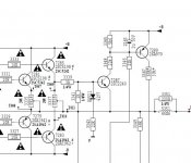
It would be nice if someone could point me to the suspect, as i'm not good enough at reading schematics to see the guilty party. BTW, are these grey 1W resistors (3364, 3358) fusible?
Thank you for reading everyone.
Last edited:
Bic410 on HiFiEngine suggests cap 2278, i'll start there.
Please anyone enlighten me as to how it (cap 2278, bridging DC input to ground) could be the culprit: in my limited understanding of electronics, if that cap is short it will send everything to ground (and that poor 7289 transistor would be overworked?). Nothing would get to the dc sensing input of the chip, so no relay output. Right?
If it's open, DC and AC will get to that input. Is there AC on that DC line? If yes (i think so, as i see nothing blocking AC to those 2 transistors downstream of the oouput stage), would that AC "cheat" up the value of the DC sensed, so tripping the relay ?
It might be not the proper place here to educate me on basic electronics, so i won't mind if i stay intrigued ;-) and everyone's time will be better used to help others.
Aren't we talking about the DC detection circuit ?
Isn't it just a smoothing cap for it ?
Will try to did out the service manual to have a look is was a few years ago so have to check.
It sure looks like a smoothing cap on a DC input line for a detector.
https://www.hifiengine.com/hfe_downloads/index.php?marantz/marantz_pm7200_service.pdf
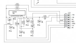
datasheet TA7317P
Thanx for looking
Last edited:
You could have a situation where the overload protection circuitry has become too sensitive.
As first thing I would replace the 1uF capacitor 2283 - these small ones tend to dry out to the point of losing capacitance completely. Once they have lost their capacitance they will pass the spikes (from thransients) to the TA7317 input.
If it were my personal amplifier then I would probably reduce also sensitivity of this particular function and put a 2.2uF capacitor there instead.
Perhaps I would double (at least) the capacitance of 2277...
Attachments
Last edited:
You could have a situation where the overload protection circuitry has become too sensitive. {...}
Ah, interesting, and to the point. But i'm now at the "not broken, don't fix" stage. See my other today's post (and be entertained?)
But i'll bet you could tell me how to change the hinge frequency of the bass tone control. It sounds like it's at 150Hz (tenor voice, and most boosted frequency of not too good speakers/earphones), i'd like it at 80Hz (guitar bottom string). Doable?
But i'll first have to adjust DC on speaker out, quiescent current, and capacitive load on the Phono input....
Thank you for your insight!
Ok, the speaker protect board is fixed. No more sound cutting. Thank you RS232 (and Bic410 on HiFiEngine)
But there were 2 surprises:
Component 2285 is not on the schematic, but it's there on that board. Right next to and in line with cap 2278 (on PCB assembly drawing (p.20 of the PDF), it would be just above the "tz" of the word "Marantz"). Connecting DC input line (pin 2) of the chip, and ground.
That would put it in parallel with cap 2278, correct?
AND dear cap 2278 was misplaced 1 hole to left, both legs on ground. I was quite amazed. It makes me wonder where is part 2284 (2283 is on main board), and what other "customisation" there is in my amp ;-)
My digital multimeter could not measure (out of circuit) capacitance of cap 2278: the display was overrange, alternating between nano and microFarad. Strangely (to me in my inadequate experience), the DC voltage test gave a few mv, a lower value after shorting the cap, and the ohm test was normal (growing).
The surprise 2285, i thought it was a resistor (did not notice its number and symbol on the PCB, dummy me). It measured like an open resistor. And resistance was not going up as on a capacitor (film) that it is.
So i replaced both capacitors, putting the 2278 cap in its proper place. I used 20 years old NOS, 2278 capacitor not reformed but it did not heat up or explode ;-)
I had trouble deciphering the color bands taking up all the space on the ever so tiny film cap. I read: Red Black Orange Black Brown, so opted for 22nano because of the barely perceptible (almost imagined) gap between Black Brown. Does that make sense in that context? Or would the reverse reading 10nano be better?
And i wonder why would that film cap would be put in parallel to the 47microF 2278? The only thing i learned, google overdosing, would be to divert more high frequency "noise"??
Anyway, it works. Sound is steady, no cutouts. It worked with the the new 2278 and 200ohms resistor i put in before realising 2285 is a cap, it worked without the resistor and only the replaced 2278 cap, and it works with the replaced 2278 + the 47nano i put in for 2285. Which is the closest I had in my NOS stash (Mouser is far away), a Philips orange Chiclets thing (mica??), 10% 100V. Am I in trouble??
Thank you all for your suggestions, they all make sense and i took note of all of them.
(and for those googling "sound cuts out" or "speaker protection" or "bottoms out" or "transients" or..., the chip used here for speaker/overcurrent protection is TA7317p (but was not involved))
But i'll bet you could tell me how to change the hinge frequency of the bass tone control. It sounds like it's at 150Hz (tenor voice, and most boosted frequency of not too good speakers/earphones), i'd like it at 80Hz (guitar bottom string). Doable?
Doable? yes, simple simulation in LTSpice.
But you are writing too much - sort out the vital issues, then return with this problem.


- Status
- This old topic is closed. If you want to reopen this topic, contact a moderator using the "Report Post" button.
- Home
- Amplifiers
- Solid State
- Marantz PM7200 repair: lacks power?