SainSmart 6N3 pre for Pass ACA

Hesitate to ask for fear of being flamed, but…

I’m building Pass ACA mono blocks to mate w/ some of the single full range driver speakers I have built, so I need a pre. I use a passive pre w/ the Dynakitparts ST-35 I built a few tears ago, but the input impedance of the ACA seems too low for this approach.

I’m not a hard-core electronics guy like most of you, nor do I have lots of cash for this project. So I want to do something quick dirty to get up & running. There are some folks on another site who seem to like the SainSmart 6N3, so I ordered one. (see: http://www.amazon.com/SainSmart-Ass...qid=1463360213&sr=8-1&keywords=sain+smart+6n3 ) I also picked up some NOS GE JAN 5670w tubes to use in place of the stock Chinese tubes.

My concern is that the transformer is labeled as 110 v. input. My wall sockets measure 124 v. (most of the time). Output from the transformer measures correspondingly more than the 6.3 v. for the heaters and 170 v. for the plates.

What to do?
1) Use it ‘as is’ & burn through tubes?
2) buy a new transformer? buy a step down transformer? (but I have no clue what to buy)

Any advice would be appreciated!

Thanks, Jim

My hobby room sale - amps, speakers, heatsinks ,parts, enclosures...(adding slowly).

I am cleaning out my hobby room, and need to clear out the shelves for new projects. I will be adding additional items in the next few days. Feel free to contact me for more information or photos.

1. Leach Amp, two modules, unfinished & untested, Panasonic FC, Wima, silver mica... 20€ SOLD!
2. PSU with speaker protection. Never used and untested. 15€ SOLD!
3. Daytona Sound Exciter NXT, just tested. 10€ for pair.
4. DC ampere and volt meter, US made. 8€
5. 6x heatsink - 10x7,2x12cm HWD, one is black anodized, 1,2kg each. 40€ for all. UPDATED to 15.1
6. 1 x heatsink - 16,4x16,9x8,8 HWD, 3kg. 20€
7. 4x spikes - gold color, 32mm diametr. 6€ for all.
8. 2x Leach Amp PCB - 10€ SOLD!
9. 2x Hifisonix Multiplier Cap PSU PCB - 20€ SOLD!
10. Hifisonix 28W Class A CFA Power Amp - 2x kx Ampifier + PSU - 20€ SOLD!
11. 4x NJW3281G and 4x NJW1302G - new from Mouser - 25€
12. 2x OPA549T Operational Amplifier - 20€
13. 2x 2SC5200 & 2x 2SA1943 Toshiba - soldered but newer used - source Farnell - 10€
14. 2x 2SC5200 & 2x 2SA1943 Toshiba - new - source Farnell - 15€
15. Dual Power Supply PCB - 5€ (8 for pair)
16.1 2x OPA541AM - just tested - 10€ for pair UPDATED to 16.1 SOLD!
17. 2x heatsink 250x76x33mm - 0,72kg - 15€ pair SOLD!
17. 2x heatsink 130x70x38 - for TO-3 transistirs - 0,38kg - 5€ pair
18. Superphon SP100 line buffer PCBs - 2x buffer and power supply - 10€ SOLD!
19. 2x speaker protection - newer used - untested - 4€
20. 2x Focal 7K415 - original box - new - 120€ pair
15.1 12x heatsink - 10x7,2x12cm HWD, one is black anodized, 1,2kg each. 60€ for all.

Plus shipping. You can pay with Paypal. Selling as is.

Attachments

  • 2020-05-09 16.34.02.jpg
    2020-05-09 16.34.02.jpg
    258.5 KB · Views: 1,781
  • 2020-05-09 16.34.21.jpg
    2020-05-09 16.34.21.jpg
    277.9 KB · Views: 1,778
  • 2020-05-09 16.34.43.jpg
    2020-05-09 16.34.43.jpg
    251.2 KB · Views: 1,753
  • 2020-05-09 16.36.06.jpg
    2020-05-09 16.36.06.jpg
    261.3 KB · Views: 1,753
  • 2020-05-09 16.36.15.jpg
    2020-05-09 16.36.15.jpg
    256.3 KB · Views: 1,729
  • 2020-05-09 16.36.32.jpg
    2020-05-09 16.36.32.jpg
    267.7 KB · Views: 322
  • 2020-05-09 16.38.39.jpg
    2020-05-09 16.38.39.jpg
    358 KB · Views: 331
  • 2020-05-09 16.38.53.jpg
    2020-05-09 16.38.53.jpg
    582 KB · Views: 289
  • 2020-05-09 16.48.29.jpg
    2020-05-09 16.48.29.jpg
    173.9 KB · Views: 272
  • 2020-05-09 16.48.40.jpg
    2020-05-09 16.48.40.jpg
    198.5 KB · Views: 242

FS: Hypex 2x UCD400ST amp with linear power supply.

For sale: 2x Hypex UCD400ST amp with linear power supply.

XLR inputs.
Power supply: 600VA with additional 12V/2A output, dual bridge, 4x Nippon Chemi-Con 10000uF
Aluminum case.

200€ plus shipping (EU only).

Attachments

  • 2020-06-21 09.29.14.jpg
    2020-06-21 09.29.14.jpg
    233.6 KB · Views: 678
  • 2020-06-21 09.29.38.jpg
    2020-06-21 09.29.38.jpg
    463.4 KB · Views: 678
  • 2020-06-21 09.29.56.jpg
    2020-06-21 09.29.56.jpg
    362 KB · Views: 663
  • 2020-06-21 09.30.18.jpg
    2020-06-21 09.30.18.jpg
    369.2 KB · Views: 675

MEGA AMP...150 pounder for P/U in CT

Anyone want a huge rare amp that needs some work?


It's an NRG model A201S. 200 WP Class A stereophonic amp. Weighs somewhere around 150 pound. The toridal transformer is the size of a wheel of Wisconsin Cheddae


Google will give you some info.


This has sat for 14 years in a climate controlled storage room since being un-exported back to this country from London. Wired for 220v. An easy conversion back to 110V? I am not a tech.


Made in Walled Lake Michigan. This amp was sent to England, then brought back here by the Brit owner...and then it sat in Scarsdale, NY until today when I picked it up as part of a large trade.


One of the photos show a Will Vincent Dynaco MKIV sitting on tip, ust for a sense of scale. This amp is huge.


I blew out some dust and took some pix. $1500, picked up in Bethel, CT. Bring a friend to help you load it.


Thanks,
Jefferson Kolle
Bethel, CT 06801
203-313-9158
kolle1@comcast.net

Attachments

  • IMG_7955.jpg
    IMG_7955.jpg
    981.3 KB · Views: 574

Where to start with Class D?

Hi there -

I know this is a DIY Audio forum, so asking for commercial devices might not get me very far, but hopefully someone here can help.

Increasingly, searching for electronics online has become a confusing slurry, further complicated by language and geographic divides.

Essentially, I'm looking for the cheapest, best-sounding stereo amplifier I can find, around 100W-per-channel (or higher). I would veer more towards "cheap" than "great sounding", but I'm not sure where those trade-offs are in Class D amplifiers.

I don't want to design it myself, but I could assemble from kit, if necessary.

My only hesitation with the kit approach is that, once again, I'm at the mercy of hundreds of different trade-offs and details that I don't have the time or money to experiment with.

At the moment, I'm operating under the understanding that a Class D amplifier will be the way to go - but that different Class D chips produce very different qualitative results with regards to audio fidelity. Those differences are further exacerbated by the wide range of designs in the world. Beyond that, it seems like power supplies are a whole other area of inconsistency and trade-off.

This seems like a place where people know this stuff, inside and out. Can anyone make some suggestions for me?

Thanks!

Octave DOWN pedal?

I have been looking at building or purchasing an Octave Down pedal which is simply a frequency divider. The biggest problem that I keep reading about is that they are ok for single notes but not chords and they have a lot of "fuzz" accompanied with them.
This has me wondering if anyone has tried to simply run a guitar signal through a variable high frequency bypass filter (say a 1MFD cap and pot) then run that through a preamp circuit to boost what is left of the signal back up and then to the guitar amp?


This would give a true frequency just without anything above say 400hz. It would not affect the chords like dividing frequencies does. Would it?


Is this feasible? Has anyone tried it?

Severe hum issue on my last project... Tube phono + line preamp. Advice needed.

Hello everyone,
so i started this project during lockdown... Already changed the components layout two/three times, there's an issue I can't solve.

Line preamp works, minor (mains) hum at full power (or gain, or volume).
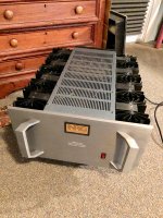
As a power amp I use my marantz 2235b at "main in" input.

Before delving in pictures and stage analysis, long story short: I've got a 50 Hz hum on both channels, controllable with the volume pot, only when the phono stage is on and working. Line preamp won't hum.
I think there's some ground loop issue, or at least some error in the grounding scheme.
As i power off the system, the hum stops.
Disconnecting the signal cable from first tube grid makes the hum disappear.
Hypothesis there is that the shielded cable (shield soldered at one side only) is captating mains EMI, but moving the cable doesn't bring anything.

Now let me dwell upon my worries, and let's have a look.

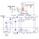
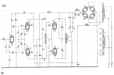
PSU + Phono schematic

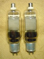
PT is 390-0-390 100mA, 3x 6,3V 5A custom made.
PSU is stabilised and regulated DC only for heaters (LM317), anodic has 6x5gt tube + RLC network rectification. Ls are 50mH.

Here there are 2 upper tubes (Vk ~147V +6,3V) and 2 lower tubes (13V+6,3V), in the lower all i can get from the PSU is +3V regulation. Possible hum source.
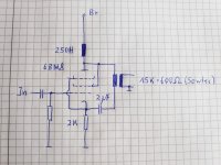
Line schematic

Totem pole, yet it works (and sounds) pretty well. 280V anodic.
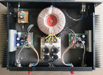
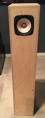
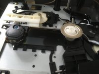
Costruction.
PLEASE if you note something wrong, give me some hints. I know it is not in order and messy, yes I do know.

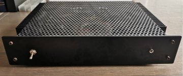
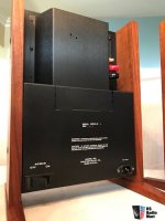
1mm steel plate (brown varnished) under, wooden frame, top will be covered with 4mm aluminium plate, with valves in the open air and power transformer on it.
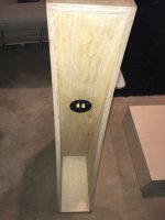
Back and front (RCA inputs and command buttons) on 4 mm aluminium. Both these plates have been grounded (i could receive radio stations with no grounding of them)

Since it is a variable eq (for LPs with deemphasis other than RIAA), i put different RC value for the first and second passive RIAA stage, those are activated by rotary switches in the front panel:


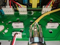
The power transformer is for the moment outside, secondary common goes to first caps' negative:


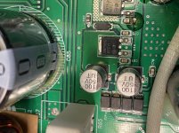
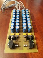
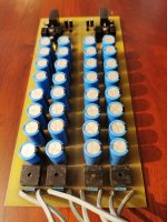
and here a picture of the PSU board:


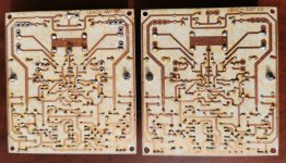
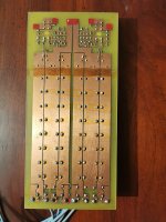
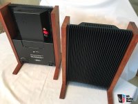
This is the boards layout:
there are three panels, two in plexiglass for rectifier and pre line, one in metal sheet (at the beginning was plexiglass as well, but wanted to try my luck against hum) for the phono part:


Input selector switch.


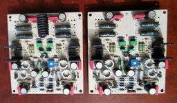
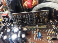
And now to the boards:
Line preamp , a normal totem pole. Volume pot common is grounded on this ground bus.


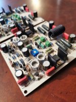
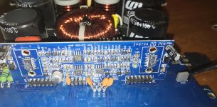
Phono preamp itself.
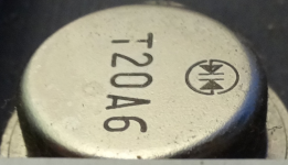
A first amplifying stage of a 6dj8, two 6sn7gt cascoded, and the last stage a cathode follower with a BJT current sink polarized with a red led. This latter stage has only the purpose to lower the output impedance.
At the moment, signal comes steady from MM RCA input sockets, for testing MC board has been left there not plugged to its switch.


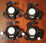
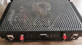
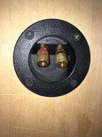
Input/output connectors:
All RCA connectors are isolated with a washer.
Tube ground is isolated from aluminium plate and goes to chassis.
MC in goes directly to MC board, ground shared with MM in connector sleeve, then chassis. However MC is now unplugged.
MM in goes directly to tube grids, cable shielding is soldered to the lower connector sleeve (yes, on one side only - wrong?), grounded to chassis
Phono OUT - comes from output caps in the phono board. Shielding to the lower rca connector. This is left ungrounded, since i connect this phono out with one of the six line in connectors and wanted to avoid a ground loop.

Line ins, shield soldered to one side only, both channels sleeves are grounded to chassis.

Line out, shield soldered to one side only, both channels sleeves are grounded to chassis.

Question: should I've soldered the signal cable shielding to both channels? I don't think so.
Question #2: I prefer to make different paths to ground for input and output rca sleeves, as well as for phono and line connectors. Is this right, or unnecessary?


Outer world connections:


And now, the dire straits (but not their music, actually 😀 )
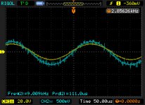
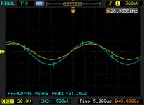
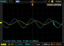
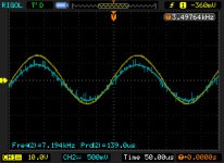
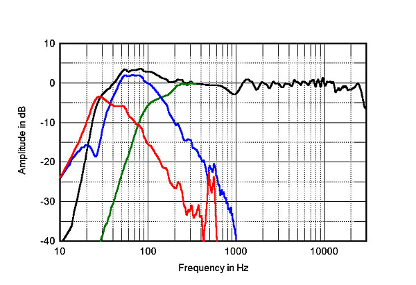
Phono on and connected, shorted inputs or turntable connected (with its phono ground): 50 Hz hum steady, rises and falls with rising and falling volume. It is visible on the scope. It is equal on both channels.

Phono on and connected, input cable detached from V1 grid: no hum.
Power transformer and inductors are quite away from the shielded (and grounded only at one end) input cables.
Yes, tried with metal tube cover grounded, anything happens.

Phono off, only line preamp: no hum and sound pretty good.

Grounding scheme:
line and phono boards are attached through a cable to the PSU ground bus clean end. The dirty end is coupled to chassis with an RC 100 Ohm/3W 10 nF/600V. Chassis is earthed to the IEC's third prong.
At the IEC, i measure 50mV between earth and neutral, 235V (european) between earth and live.

At the moment, but I'm aware it's wrong, connectors ground goes directly to chassis (and no, didn't want to try Sakuma's 😀), yesterday hadn'the time to plug them to the clean end.

Phono ground, metal front and back panels go to chassis, so does the 20v DC common for the led in the front, so do the two MM/MC and phono/line DPDT selector switch metallic cases (I grounded each tiny piece of metal there is, this thing is so sensitive to anything)

Now, my next thing will be to succeed to get LO ref up to 13V instead of the actual 3V, but however this is DC so it shouldn't hum.

So please, now it's up to you. After 2 months spare time trying to solve this hum, I'm well exhausted, I have no ideas left (apart of course the RCA grounds to the bus), and I had a couples of dreams (or nightmares 😕) at night.
Go with your suggestion, ideas, critics, praises, compliments, disapproval, but pleeeeeeeaaase some input (possibly shielded and grounded 😀😀😀)

PS. I know it's messy

25 LED Chaser Transistor Outputs.

Hello,

I have made a 25 LED Chaser, However I want to have more current for my LED displays. Which transistor will give good current I was thinking of BC547's Or the 2N3904. Also could anyone tell me If this Is correct but on a schematic I saw that a 2N3904 collector was put on a positive supply the base was to the outputs from the IC's and then the emitter went to the LED's, Is that correct ?

Thanks,

Digital.

B&C DCX464 build

Hey guys I want to give building my own speakers a try. I’ve done diy subs in the past and even build several kit speakers but never a complete diy speaker. Based on my readings here the DCX464 seems like the best candidate to build the ultimate end game towers that can double for both HT and critical listening. If any one is familiar I would like to build something like the Diysg 1299s or realistically more like the JTR 212HT. Due to the size requirement of horns to fully load the 464 I am considering crossing it much higher than the 300hz it’s rated for. I can’t seem to find many build using this setup. Has anyone here built any speakers around this CD? If so I would love to hear your experiences and what you learned in the process.

Mini turret boards?

I am building a simple circuit. It were will have 2 small diodes , 1 resistor and a small power rail. Would g10 epoxy board be overkill? I want to make the board 1”x2” approximately. I want it to be a small point to point board. I would think 1/16” would be sufficient? I would like to use small turret lugs that would fit snug. Can anyone help with where to get these things?

Higher frequency application, no coils

Hello everybody,

Please pardon me, for posting in a diyAUDIO forum about a non-audio topic, but there seems to be so many knowledge floating around here, that I hope you might be able to at least tell me, if my idea has a chance to work.

We do not drive speaker coils with our application, but charge ions in liquids by capacitive coupling. So we have square signals of different voltages as signal shape. We need frequencies of up to 130kHz to change from one voltage to the next, but at very small power levels. Until now we use a classic class A/B op-amp. Trying to cramp this into a small voume box, we run into thermal problems. Active cooling is difficult due to the space constraints.
So the idea is, to use a class-D amp instead of class-A/B, to reduce the power consumption.

Problems I see:

  1. I did not find any ICs on the vendors' shelves that allow output frequencies of up to 130kHz (instead of the typical 20kHz in audio); so we probably have to tackle a discrete design. Is there anything available for our purpose that I did not spot?
  2. Our first thoughts are to go up to 20MHz frequency to be able to shape the edges: We are however afraid that this would lead to massive losses due to the capacitance of the transistors. Can this be solved with dead time? Are their suitable transistors available with low capacitance?
  3. With regard to the low-pass filter we have no speaker coil to be used as inductance. Worse, we have capacitors as load. What would be your approach to handle this?
  4. Can the problem be simplified by accepting higher distortions and imperfect signal shape? The only thing we really need in the end is the correct amount of ion charge; it is not important at which time of the loading signal period they ended up there. What we need are steep attack/decay on the signal edges of the rising flank and exactly the same amount of charge, i.e. very good reproducibility.
Can this be done, or are we out of luck and my idea is void?


Best regards

6J1 Preamp

Just got a 6J1 buffer preamp in the mail. Its the Little Bear preamp that uses 6J1 tubes. Cost was $30.

The Chinese 6J1 tubes are squishy sounding. After replacing them with USA 5654 tubes it came alive and sounds really great going into a solid state amp.

Looking at the schematic, the tube section is above ground, fed with +28 and -28 volts from a split rail supply.

Is this a way of getting a plate voltage of 2 x 28, or 56 volts on the plate? Or does it not work that way?

Attachments

  • 6J1 Preamp.jpg
    6J1 Preamp.jpg
    143.5 KB · Views: 849

  • Locked
FS: Frugel-Horn Mk3 w/Fostex FE126En drivers. Pro build

Selling a pair of Frugel-Horn Mk3 speakers with Fostex FE126En drivers. Professional CNC build with the driver mods to improve performance. Internally damped with the recommended wool sheets and fibre fill. Spikes installed in base.

Asking $375.

Located in DFW and prefer pickup but can ship at buyer's expense.

Also available as a bundled deal with a Sachiko backloaded horn speaker here
https://www.diyaudio.com/forums/swa...ckloaded-horn-custom-cabinet.html#post6208853

Attachments

  • fhMK3.jpg
    fhMK3.jpg
    369.6 KB · Views: 870
  • IMG_2878.jpg
    IMG_2878.jpg
    713.6 KB · Views: 848
  • IMG_2879.jpg
    IMG_2879.jpg
    391.6 KB · Views: 832

FS: Type 26 triodes

Hello all.
Cancelled my 26 line stage project, so I have the following available. All were bought off Ebay from established tube dealers. I have the vendors I bought from for each of the tubes.
I can't post pics on this site. If interested I will forward pics, testing info, and original Ebay seller directly to your e-mail that you supply via PM

First up:RCA Cunningham 326 26 Globe Tubes, Quad, Tested. I paid $ 60.00 for the quad. Will take 20% off the top. Sell for $ 48.00/quad. In white tube boxes from Arizona Supply.

Matched quad # 1: 4 x #26 Philco Tubes*NOS*NIB*Very Strong Quad*(M-R). I paid $ 140.00 for this quad. Again, 20 % off the top so $ 112.00 for this quad. Original Philco boxes.

Matched quad # 2:Vintage Philco 26 Vacuum Tube Unused All in Nice Boxes. I paid $ 128.00 for this quad. 20 % off equates to $ 102.40. In original boxes. 3 Boxes nice, 1 kind of crappy.

One New Type 26 Tube, Philco, New-In-Box. Paid $ 20.00, therefore price will be $ 16.00.Box kind of crappy.

PAIR OF NATIONAL UNION TYPE 26 TRIODE VACUUM TUBES TV-7 TESTED AUDIO AMPLIFIER. Visually appear brand-new. Paid $ 35.00, price now $ 28.00. In original boxes.

Westinghouse (RCA made) Type 26 NOS/NIB vacuum tube tested and guaranteed. Pd $ 22.00, therefore now $ $ 17.60. In original box

2 Matching ~TYPE 326 CUNNNINGHAM Globe Radio Amplifier 26 Vintage Vacuum Tube #1. Paid $ 35.00, now $ 28.00. No boxes

Please note the first sentence in each description is cut and pasted from the original Ebay listing.

Please note I deducted 20 % from what I paid for all these tubes.

Here's the deal. For US buyers, shipping on you. I'll cover insurance if needed.
International buyers, shipping and insurance on you. Please understand that I will only ship internationally if it can be insured, which leaves out the cheaper USPS method. Also I will not lie on a customs form.

these prices are good for PayPal friends and family. If you don't pay via FF, the PayPal fee will be added. Sorry.

Email with any questions and pic requests. Thanks for looking and be safe.

Cheers, Crazy Bill

Compressor time constants. How do I go from attack/decay times to db/ms?

Ive been designing a compressor pedal and run into a problem on the atck/dcay times. Trying to match the ssl bus compressor that has attack times of .1 1 30 ms and decay times of .1 .3 1s decay times. These times are only half the info. How many dbs does it compress in that time? The full 60db or a more practical number like 10 or 20db? The pedal design in LTspice shows db/ms. How do I relate these two?

Newbie need help building a subwoofer

this is the situation:

the project is a SW for a 2.1 system (2 DIY amazing DML speakers!) medium size living room

the amp of the sub is a20W mini amp (MUSE EX2)

I am building a box of maximum 21 L (concrete cast)

I have a: Dayton Audio SD215A-88 8" DVC Subwoofer
+ Dayton Audio DSA215-PR 8"

at the beginning I planed to put them on a sealed box and all is good. now after watching some WINISD videos I'm not sure at all what to do.

I have 2 main questions for you:

1. do I have to have a high pass filter because of the cone extrusion? if so can you show me a reference product? (Butterworth 40HZ N2 ? gave the best result)
2. the data I'm getting from WINISD is better when I use a ported style setup, not using a PR at all...is that make sense?

Tube sockets and audio grade caps

Hey folks.

I've finally built my amp after months of learning and feedback thanks to you folks.

Here's the final design(x2, since it's stereo).

mknTAeo.png


I think it sounds great, however, I have a couple of questions.

First, I had a problem with bass, especially repetitive like with four to the floor music. My speakers would "pop" very often. I'm not sure of how to describe it better. They would just jolt audibly and ruin the sound. Both channels would do it at the same time. I thought because I was using my prototype tubes(which I thought I surely damaged being a new learner), I'd swap them out. Still happened. I used a ECC81 in place of the ECC83S, same problem. I thought maybe it was a PSU issue, but even after switching off the AC it runs without distortion for at least 2-3 seconds, so I figured the tubes are sufficiently supplied.

I put the ECC83S back in and the problem never occurred again. As a software engineer by trade, I hate unreproducible issues. The only lead I have is that I have basically reseated the ECC83S and perhaps made a better connection.

I bought these sockets, as I heard porcelain was the worst for tolerances:
The Tube Store - 9 pin socket

They seem just as bad but I went with it. The pin alignment is wobbly and only fixed because I used solid core wire to solder to it. Do folks of this forum have a preferred socket that is solid and has no physical variance?

Does anyone think there is something wrong with my circuit that could otherwise explain this popping? (although I can't reproduce it)

Second part of my question. I have a partial bypass cap on the KT88 at the end. I used a run-of-the-mill electrolytic. In the books and online I've seen so many people say you should use an "audio grade" capacitor for bypassing, but they never say much more about it.

Can someone tell me exactly what qualities make a cap audio grade? Low ESR? Something else?

Well, another SS amplifier Chassis Idea...I kinda like this!

This makes building a SS amp chassis to another level. I kinda like it...got enough sinks, trannies, and other crap to build a F5 this way...

Whatcha guys think?

Its an Audio Audire amp....Class A too!

Would look perfect flanked to Magnepan Tympani T-IVa, yes?

Attachments

  • 1919461-974c81da-audire-noble-1-monoblock-amplifiers-75wpc-class-a.jpg
    1919461-974c81da-audire-noble-1-monoblock-amplifiers-75wpc-class-a.jpg
    35 KB · Views: 232
  • 1919462-87107e0f-audire-noble-1-monoblock-amplifiers-75wpc-class-a.jpg
    1919462-87107e0f-audire-noble-1-monoblock-amplifiers-75wpc-class-a.jpg
    45 KB · Views: 235

VOX style EL84 PP amp questions

Hello!

A friend of mine requested me to realise a Mojotone NC3015 for him, but im stuck with the question of what power and output transformer to use.
Here (Central Europe, Hungary) we have some available, made by Indel, after searching the net for clues, I saw that maybe an Indel TGL20/002 could be used for the output.
Is my assumption right?
He wants to stick with the tube rectification, I reckon that separate heater voltages should be used for the EL84s, the ECC83s and the EZ81 too. The Indel TSL100/001 seems the closest I can find here with 2x260V, 1x6,3V, 2x3,15V and 1x5V, altough the EZ81 also requires 6,3V heating as I see.
I can not find any info on how much is the anode supply on the original trafo used, I have a feeling that this is much higher than what originally needed. Is there a way to modify the circuit to fit these two transformers into it?

All of your help is appreciated, thanks in advance!

Attachments

Help with Diffraction Peak

Hiya,

I have been having some issues designing a work-around for a diffraction peak in a 2-way loudspeaker (Jordon JX92S, Vifa XT19).

The modelled response of the Jordan in-box is using Jeff Bagby's diffraction simulator.

W_DIFF.png

The measured responses on-axis, 15-degrees, 30-degrees and 45-degrees off-axis at 1m are as follows:

on-axis.png

15deg.png

30deg.png

45deg.png

These are measured using the UMIK-1 measurement microphone and analysed usine REW, using a Tukey 0.25 time-window of 2.2ms, which eliminates the floor-bounce and longer reflections.

I'm not concerned about the low frequency rolloff which is a combination of the baffle-step and the time-window and can be easily compensated with a low-frequeny shelf.

However, as you can see there is peak around 1.4kHz of about 3.5dB, corresponding more or less to the model. As the peak is in the model as well as the on- and off-axis responses, I think the peak is real, rather than a measurement artefact.

I'm planning on crossing over at around 2kHz. I can't go too much lower due to 2nd-harmonic distortion from the tweeter at around 650Hz.
TW_THD.png

I'm using Charlie Laub's ACD for modelling the responses and MiniDSP for the implementation.

I was aiming for a straightforward LR4 with digital delay for driver offset compensation, but as you can imagine, the 1.4kHz peak keeps showing up.

Any ideas? I suspect the peak will be audible. I guess a shallow notch could be an option, or perhaps lowering the Q of the low-pass crossover filter, so it starts attenuating a way before the Xover frequency? Unfortunately the box is designed and finished, so acoustic/physical mods aren't possible.

Am I getting this right or am I missing something - I suspect this must be a common issue?

Thanks!

Tweeter to match JX92S

I'm looking into building a MLTL design using the Jordan JX92S

http://documents.jordan-usa.com/Enclosures/JX92S-31-MLTL-MD.pdf

The JX92S is an excellent driver when used in a fullrange, but as is typical with many full-range drivers, has a poor off-axis response. I'm planning on adding a tweeter which can be optionally enabled with a simple (ideally first-order ) crossover. I will then be able to listen to them either full-range for superior imaging when listening directly in the sweet-spot, or as a 2-way.

Because of WAF, I don't want to increase the height of the enclosure too much. I'm also keen on mounting the tweeter as close as possible to the fullrange, as I would probably keep the crossover frequency high (maybe 6kHz) and I want to avoid lobing effects as much as possible.

Another factor is that the Jordan has a rising on-axis response, which means that it is better used off-axis. This means that the partnering tweeter should have a very good off axis response.

The question, as always, is which tweeter to use. I've shortlisted several models including
Vifa's XT25SC90-04, NE19-VTS-04, XT19TD00-04 and SB Acoustic's SB29RDNC.

Has anyone had experience of using any of these units?
My requirements are:
- small faceplate to allow close mounting
- good off-axis response
- excellent THD
- Good subjective performance.

I may also consider cutting the tweeter faceplate with a router to allow close mounting.

Any opinions gratefully received.

Ant

Sparkos Labs power supply kits?

I thought this was interesting - Sparkos (known for their discrete opamps and regulators) now is selling dual and quad output power supply kits. I have not tried to do a bom to see if their prices are competitive, but they seem ball-park reasonable.

Audio Power Supply For Audio - Sparkos Labs, Inc.

What seems a bit unconventional is that they place 1 Ohm resistors in series with the transformer leads "to reduce inrush". Seems like they do not subscribe to the use of varistors. Of course, you could just use varistors (typically on the primaries) and get rid of the resistors if you wanted.

Searching for an OB subwoofer

I tried the search function first but couldn’t find an answer, forgive me if my first post is redundant and please direct me to the post that will offer insight!

I’m in the planning stages of my first fully OB speaker. I’m searching for 12” or 15” subwoofers that will work well under 50hz, extend to 500hz or more and are easy to purchase in Canada. I found the AE brand, but they have no Canadian presence so buying gets very expensive after exchange, shipping and duties.
I also looked at the Eminence Alpha 15A, but I fear it won’t have good output down low. I even considered some car audio options, but they lack any lower midrange capability.

Can anyone offer me a few options to look into?

Thanks,

Help finding rail fuses in an old B&K power amp

Hi 🙂


I have a B&K ST1400 power amp from the 90’s (?) that is exhibiting signs of it’s age, and it is outputting really low level - no where near where it used to be.


Someone who knows about this stuff a lot better than I do, recommended that I change the rail fuses.


Are these them?


http://jeffreyhayat.com/temp/bk.jpg


Thanks in advance.

Attachments

  • bk.jpg
    bk.jpg
    447 KB · Views: 244

Changing box sizes with the same box liters?

Hello everyone I hope everyone is doing okay? I am looking at building a box for the Fostex FF85WK driver's. I am building my own boxes through trial and error. So let's say my box is 10" inch's tall and I want it 8 inch's tall. I can make up the lost height in the depth of the box or how wide it is? . As long as it match's the liters or Cubic feet the program put out? Is this correct? I am able to change the liter size and shape's with out having any drivers in the data base. It's so much easier and I am not fighting with the set box shape. I hope I am making sense here. I just need some help here. Thanks Jeff

Total noob with power supply noise

I built a portable class D amp with a TPA3118 and a preamp. It's powered by 8 AA nimh rechargeable batteries, but I added a power jack so I could recharge them without having to take them out. I know it's not the best way, but my plan was to recharge them with a 12v adapter.


Now, the amp works great on batteries, but gets awfully noisy when I connect the 12v adapter. I thought the voltage difference between the batteries and the adapter might be the culprit, so I took out the batteries: the noise persists. Then I tried my laptop's adapter: still the same, if not noisier.

So I figured this must be a common problem for amps, and there must be a generic way of filtering out this noise. But as a noob, I have no idea.

10 and 12 inch PA drivers for home use in 2 and 3-way designs €100-150

I’m looking around for some lower end / cheap PA drivers with decent performance in simple 2 or 3 way designs in combination with HF compression drivers for the most sensitive solution and possibly a small midrange of some sort which I can decide later. I’m looking at both 10 and 12 inch woofers, Klipsch Heresy and JBL43xx styles. Deepest bass is not necessary I’m happy with 50hz but I enjoy some body and power.

I have experience with Eminence coaxials and happy with those, and already have plenty of HF drivers laying around for this use. I have been looking more into the Eminence standard range Alphas, Betas, Deltas 10 and 12s etc, they get good review and seems like quality build but I don’t want to narrow my search to this.

I’m also considering Fane Sovereign series in particular 10-300 and 12-300, they are better priced in Europe than Eminence and I seem to get more for the money and I have good experience with Fane fullranges from earlier seems like quality drivers too.

Other brand that can get good prices on here is P.Audio and Celestion. The later is interesting, I’m wondering if their bass guitar drivers can be used for Kemal speakers as well? For instance the Pulse 10 and 12 looks very interesting.

Then out of nowhere a brand I have no experience with showed up while searching Celestion, Monacor? They have a few models that seems very interesting but I have no experience with them. A few examples is SP30/200PA, SP10A/302PA and SP-300PA which all looks fitted for my purpose just as much as the Eminence and Fane drivers I have been considering. Is Monacor a serious vendor and are their driver of good quality compared to its price and the competition here in Europe?

Are there other models in the 100-150 price I should consider? I’d like to have 94dB/w minimum in the area of 50-500Hz in a 40-50l box, preferably also flat up to 2k if possible so I can decide on midrange later.

Noise from bridge rectifier

Hi everyone,

Thanks for a great forum! I love to read and learn about DIY audio in this forum but it's still quite new for me, please bear that in mind 🙂

I have a couple of questions about a preamp I am creating.

The preamp is going to be powered by 17VAC (there's no other option) and I have made a full-wave rectifier with a couple of parallel 100uF reservoir capacitors. The voltage is measured to ~42VDC without load.
Under load, the measured voltage is 31.8VDC which is sent into an LM7818 which converts it to 18VDC.

- Is it correctly understood that the LM7818 doesn't take any damage from this voltage since it's maximum is 33VDC or is it actually being served the 42V and therefore burning out over time? Why does the voltage change when a load is present?
- I am using four 1N4007 rectifiers in my bridge. They make some noise when increasing the volume. Is it possible for me to remove the noise, e.g. with other rectifiers? I've read that MUR860 should be good for audio components. Would that remove the noise?

Thanks in advance and have a nice evening! :goodbad:

L7 MOSFET amp test 20-350kHz

Have a friend who has been asking me about about the MOSFET is not really can output 350 k sine wave. And attenuation is less than -3 db.

I take out the time to do a test.

From the test chart and see this is true. Can be achieved.

But it should be noted that the test I cancelled ZOBEL 10 ohm resistance.

Attachments

  • ????0.jpg
    ????0.jpg
    47.5 KB · Views: 864
  • ????1.jpg
    ????1.jpg
    45.9 KB · Views: 863
  • ????3.jpg
    ????3.jpg
    49.1 KB · Views: 841
  • ????2.jpg
    ????2.jpg
    47 KB · Views: 841
  • ????4.jpg
    ????4.jpg
    48 KB · Views: 819
  • ????5.jpg
    ????5.jpg
    48.3 KB · Views: 194

UN07 and UP07 JFETs

Anyone know anything about these JFETs or recall ever seeing some in any specific gear? Not sure who made them, but the packaging is TO-126. There is next to no zero info online about them that I could find. I've got 4 complementary pairs in each stage (line, MM, MC) of my Stax preamp (Echowars mentioned this JFET in the Stax's repair thread). The preamp also uses K117's, but those can still be found. As difficult as it might end up being, I'd like to track down some spares, or a good drop-in replacement. Just in case something ever goes wrong again, as it had an issue with a K117 in its last life. Worst case, I could move some around between the different stages, but then something would still not be working.

Any help would be much appreciated!

Adjustable distributed load discussion

I'm afraid the Hafler and Keroes paper is a piece of "!%*!*?*" that keeps getting quoted endlessly. It's a little overdue that this mess got cleared up.

I just worked out the output Z formula for UL and it essentially gives smooth variation between the triode Zout (or Rp) and pentode Zout as 1/U% ie. (43% UL => U%=0.43 => Zout = Rp_triode/.43)

The effective Mu for the circuit also varies as 1/U% from the triode to the pentode case.

All H & K's chart shows is the effect of a bad mismatch between the tube and output transformer impedance. If the transformer had been properly matched to Zout for each U% on the bottom axis of their chart, one would just get the normal expected performance for a triode with that effective MU and that effective Zout. There is NO optimum U%.

There is nothing special about the 43% or 20% in their charts except for the particular transformer and tube they happened to use for that test. The optimum point on their graph is where it just happens to be matching that tube.

Another serious fault launched by that paper is that one can get away with using the same DC voltage for the screen as for the plate B+. The sharp dropoff in plate current on the left side of all pentode characteristic curves is due to screen capture of plate current when screen voltage is near plate voltage.

Just using a tap off the output primary for the screen causes distortion to set in seriously just around idle conditions. This means the first watt is literally ruined. Hence the bad rap UL got for sound.

The screen should be lowered by at least 50 to 100 volts below the plate to avoid this distortion. A separate winding for the screens is one way to do this, but now-a-days one can just use a resistive divider off the plate driving a low capacitance MOSFET follower for the screen.

Sorry to sink a few sacred ships, but this needed to be corrected.

Don

Teac VRDS-7 Need Help

I take out the CD tray to change the laser pick up,after completed the job. Try to play a disc but the clamper is not going up , I turn the main gear manually let the clamper up . After play a disc , press the OPEN button ,the tray go out but the disc still hold inside-because the clamper not going down. I hard work a week can not solve.

Attachments

  • IMG_0593.jpg
    IMG_0593.jpg
    747.8 KB · Views: 239
  • IMG_0594.jpg
    IMG_0594.jpg
    848.9 KB · Views: 289

Seeking inductors 3uh and 22uh, yes for a Quad 405

I have another thread relating to PCB procurement for a Quad 405-2 but as this is common to many amplifiers I thought to create a new thread.
I require 2 inductors 3uh for the bridge circuit and a 22uh in the output circuit. From reading it appears the 22uh tolerance is not so important but the 3uh should be tight.
I do not know what the original current rating was for each item, a search on ANCO 440 leads here and nowhere else of use. I have thought about winding these myself on ferrite cores but the online calculators suggest something fairly huge if I specify 18AWG wire on the 22uf. If I wind them my work will be very accurate but I have no means to measure the resulting inductance so how accurate are the calculations transposed to wire and ferrite? Would it be possible to follow the recipe from the calculator and arrive at a tight tolerance or does someone who has built Quad clones have some product links?
There is another older thread related to this question, I do not consider it was resolved, there was also some contention.

VRDS 10 doesn't spin up

Hello,

I have seen some thread about VRDS10.
In my situation the tray is working fine. After power on the laser moves inside and the lens moves three-four time up and down as manual details.
With the cd inserted the mechanism push the cd up, the laser assembly goes inside but the motor doesn't run.
I checked ( with service manual) the test point but only the first step because the others must be verified with the motor running

Any idea?

There is a way to check the light of the laser?

Thanks

Walter

KT-88s: To the Pain

Apologies first for the cheesy Princess Bride quote, and second for starting a thread that will probably seem similar to several others here. I couldn't find anything exactly like this, so here goes...

My goal is to design the output stage of a music instrument amp using a pair of KT-88s. Subject to the limitations listed, I wish to extract every Watt possible from these tubes. Every. Stinking. Watt.

I wish to eliminate or at least minimize crossover distortion, so Class B is out.

Although I'm a fan of Neil Young, blocking distortion is also a no-no.

I wish a pair of tubes to have a lifetime measured in months (years if possible) and not hours, so super hot-rodded lab curiosities are out.

I do not wish to have any solid-state devices beyond diodes in the signal path. Sorry, source-follower lovers. I do not object to them elsewhere in the design, for example, in a rectifier.


Edited to add: I don't want to use any tubes that can't be found at your local music store. So, things like 12AX7, 6L6GC, El84 are fine. 300B, KT120, 6SN7GT, probably not.

Aside from that, anything goes. I do expect to be hitting this output stage with some severely clipped signals from time to time, and to sometimes drive it into clipping regardless of what comes in the front door. So, any topology that fits the above is on the table, such as screen drive if that fits. I may be interested in winding my own transformers, so consider impedences as "free" and concepts like coupling transformers in play.

Here's a summary of what I've considered so far:

I consider everything to the right of the left-hand side of the Ra curve to be available, as if the tube was some sort of big diode. Given that, maximizing power with an acceptable tube life seems to be an exercise in drawing a class-B loadline that does not exceed an arbitrary plate-dissipation number. For that number, I have chosen 96 Watts, based on the fact that a couple of successful commercial designs have loadlines that are in the 94-97 Watt territory, namely the 200W Marshal Major and the Hiwatt DR201 and DR405 (about 200 W and between 300-400 W respectively). The Marshall and the DR201 use 2 pairs of KT-88s in push-pull, the DR405 3 pairs. I'm only using one pair, but I want to see if I can get more power than that from my pair by using clever design.

If I want to refer to previous work, I should also mention the Fender PS 300 and PS 400, which used 2 and 3 pairs of 6550As, rated at 42 Watts plate dissipation, in Class AB2. Va(o) was 700 V, Vg2 was 350 V, and I don't know what the load line was because I don't know the impedance of the output transformer. So, they may have been able to run at lower maximum instantaneous plate dissipation by getting more voltage swing and current swing via Class AB2 (or more power per pair at similar dissipation levels).

I figure worst case is a clipped input resembling a square wave at just the wrong signal level, which would give me a continuous plate dissipation of 48 W. The commercial amps survived that, the Marshall with about 60 V of sag at the center tap. I suspect the sag for the Hiwatts was minimal as both the output transformer and power transformer were huge.

Playing with loadlines, I find I maximize power up near maximum allowable B+ of 800 V, and output impedance at 6.7k Ohm. At the opposite end of the loadline, current swings up to about 430-440 mA at about 70 V. To get current up that high, I need Vg2 at least 350 V or so. Pout is a rather fabulous 158W, if my calculations are correct.

That led me to my first real obstacle. At that plate voltage and screen voltage, screen dissipation is unacceptably high, some 20 Watts or so with a clipped waveform. I began to look at Class AB2 operation for relief. I don't know much about AB2, but looking over the 6L6GC datasheets, I was led to believe that available plate current can be raised by either going to a higher screen voltage or by taking grid voltage positive, and that for a given available plate current, screen current will be about the same no matter which scheme is chosen. If that is true, I can lower screen dissipation by keeping screen (and plate) current about the same, and trading off screen voltage for grid voltage (not at 1:1, of course).

I started wondering how low I could go on the screen and how high I could go on the grid, and that led me to this circuit from the GEC KT-88 datasheet. It's a Class B circuit rated at 150 W with RL(a-a) at 6k Ohm "for speech only". 7.5k Ohm is recommended for "other purposes", and I estimate the circuit would produce maybe 120 W with that load.

Now, this is a Class B amp, but I'm more interested in what's going on inside the KT-88s. Under "Operating Conditions", it lists Vin(g-g)(rms) = 360 V. Just to verify this isn't a misprint, the text reads, "Both grids are driven into the positive region from a driver stage capable of providing 180+180V r.m.s., the current drawn by the control grids being limited by R18 and R19." R18 and R19 are listed as "22-100k Ohm 1W".

Maybe I'm just new at this, but if I understand this right, that means each grid is getting hit with a positive 255 V at peak. I struggle to comprehend KT-88 operation under those conditions.

So, let me summarize what I hope to learn:

Is there any other topology or arrangement which would allow me to extract more power from these tubes without blowing them up? Meaning, other than a more or less conventional Class AB2 grid-driven stage with fixed bias, or other than some variant of the attached schematic?

Is there any other way to lower screen dissipation at these power levels?

Can I modify the circuit in the attached schematic to run in Class AB2 instead of Class B? Or is there something that works even better?

Thanks for your advice and suggestions.

Attachments

  • GEC Class B Amplifier.png
    GEC Class B Amplifier.png
    608.7 KB · Views: 729

Pam8301, how to connect line in?

I built a small amp with a pam8302 and it worked great.
I have now a pam8301.
According to the datasheet for the 8301 it only has a single line in connection, and it isn't signed. Which line connects? The + or -? And where would I connect the other?
https://www.google.com/url?sa=t&source=web&rct=j&url=https://www.diodes.com/assets/Datasheets/PAM8301.pdf&ved=2ahUKEwj74cfakpLsAhV5pXIEHXEpDsgQFjAAegQIAhAB&usg=AOvVaw1CrazjSNJdavrLsu-h84e5&cshid=1601512500316

LJM 12-2 ver4 gnd short to signal gnd.

Hi all


My first post here so please be patient.


I have built my first diy ampli with LJM 12-2 ver4 amp. It's decent but doing FFT i see harmonics on 50hz, 150hz,250hz and so on.

I was trying to solve this but I found that speaker ground is shorted to signal ground. I wonder if this is normal. My main network work at 50hz but strangely to me I don't see 100hz harmonic. I think this is related to main 50hz but why I don't have 100hz harmonic ? 150hz and so on are even bigger then 50hz harmonic.
I did the same FFT on my NAD 902 and I don't have this problem.

Can someone help me clarifying this ?

Tweeters for Quadral Ferrum 700

I want to repair a pair of Quadral Ferrum 700.
The original tweeters are gone.
Quadral wants 69,- € for a single replacement tweeter.
Since i do not really need those speakers that is too expensive to me.

Now i´m looking for a cheaper replacement part that matches the parameters of the original speakers quite well.
I don´t find any information about those parameters....help please!

High Time

Joined 2013, but did not do a lot 😱
Somehow i recently talked myself into a Paradise build, so things changed - more questions during the last weeks than during the 7 years before.


Born Austrian, studied in Canada, worked in Eastern Europe most of my life and retired in Catalunya. Quite active on Lenco Heaven (some of you may have heard of it 😉 ) as "wer", where i also provide small bits and pieces for record players that can be done on a Chinese mini-lathe.
My knowledge of electronics is very limited, but if i have a good day i can ay least do some acceptable soldering.


Thank you all for an interesting forum on a very high level, even if at times it is way too high for me 😕

FS: Aleph-j in deluxe 5u chassis

I’m selling my beloved Aleph-j in deluxe 5u chassis. It’s my first class A amplifier and changed my opinion on how much of a difference an amplifier can make. I have an EE degree with experience in electronics and carefully built this wonderful amplifier. I’m only parting with it because the wonderfully efficient speakers I’m completing are begging for a SET amp🙂

If you are in the greater Denver area you are welcome to bring your speakers and make sure you love it as much as I do. I did not install any LED’s due to personal preference. Used Antek 20v transformer. The other parts came from Diyaudio store transistor kit and standard parts from the BOM.

I’ll add more photos Sunday afternoon. This one photo is while I was building. Asking $1k plus exact shipping cost.

IMG_0314.jpg

Tas5630 with DSP board for Subwoofer

Hi All,

Currently in the process of designing a ported subwoofer, with true RMS of around 300w. it should be cost effective as well.
Problem is, If i start looking for a driver which gives a good response, is expensive.
So, planning to add a DSP which can be tuned with a USB port! and integrate it with TAS5630 in PBTL mode.

But I lack the knowledge of designing and integrating a DSP with a Sub board.

I know this is an untapped segment. But, this might help me a lot. Guys, who are experts in this, please help me.

Thanks,

F.S.: DIYaudio store’s F6 PCBs, two pairs of IRFP240 and four 5.1V Zener diodes

SOLD

For sale: DIYaudio store’s F6 PCBs, two pairs of IRFP240 and four 5.1V Zener diodes. The PCBs are unused, the power MOSFET pairs are matched so their Vgs figures are within 10 mV from each other, and were selected from a batch of 300 pieces, all with the same manufacture date code.
The price is $45 shipped with a tracking number in the USA.

LTspice example: simple zener diode voltage regulator

What a wonderful resource this forum is!

Over the years I've learned and forgotten and then re-learned LTspice several times. This time around, I'm writing up my learnings in blog posts, so that years from now when I've forgotten it all again, at least I'll have a reference 😀

Here's a first post: a basic zener voltage regulator Basic Zener diode voltage regulator * GitHub

Cheers!

Chinese Amp - Just what did I buy?

With so many cheap Chinese amps available I can't have been the only one tempted to buy something ready made. So rather than completely hi-jack a thread about building amps I thought a new one about what people have bought or are thinking about buying would be good. including pre assembled PCB.

I've bought but it hasn't been delivered yet an Amp claiming to be a 12 watt per channel JLH 1969 Class A amp in two cases one for power supply one for the amp. All is not quite as advertised though - as has since been pointed out to me the heat sink is too small for 12watt class A amp. A closer look at some of the photos shows a pair of OP Amp chips next to the volume pot View attachment JRC5532-JRC.pdf

Here's the Amp
LP Spirit Pure Class A 1969 Amplifier Computer Desktop Mini Merge Split Type HIFI Audio Power Amp|audio power|power ampa class amplifier - AliExpress

We've all seem tube amp hybrids - this looks more like a 1969 JLH hybrid now. It might even deliver the claimed 12 watt per channel what do you think?

Live Sohn concert.....amazing!

I have watched this several times now and I can't really get over how good it is...all subjective of course.

It sounds crystal clear and the picture is also very good if that bothers you. I find playing good music through a good system that includes a good size high quality picture really gives you an immersive experience....i damn near shed a tear!

SOHN - Live with the Metropole Orkest - Full Concert - YouTube

RR125 from rega

rega RR125

Ok, here it goes: does anyone has any experience with Rega drivers or their speakers (like Kyte, RS1 and so on...). I had some decade ago their small Kyte speakers on stands and like the big, spacious soundstage with realistic timbre and good vocals. Only big speaker offered me later better performance.
I had some fostex (fe206e in front horn and fe103 but they seem to make sound too monitor like and not so lifelike). I admit I forgot the 103 performance but remember liking them somehow with smaller pieces of music (vocals, chamber), but did not like their smallish power and dynamics. The sound wasn´t as big as with Kytes either.
Now, I got some old JR149 speakers that have the bass 5" unit missing but the tweeter is there. They look promising as they are of oval aluminium shape and will use them as my working speakers. That means 1m max. away and fed by pc with DAC and amp (still deciding to buy either a smaller tube amp or some chip T-amp-never heard them and want to try one, now I have quite good old Sony reciever, the STR6046 model).
My question is - this driver RR125 from Rega or some new Fostex like FF 125 WK full range.
There is also possibility that I replace the tweeter and put some planar ribbon there to cover above 7khz if the RR125 driver doesn´t go so high as FR (something like jr149 , below).

What scares me is the aluminium dustcap on the FF125 WK. I usually detect metal membranes immediately and my ears are fixed on paper sound as an ok element. Even big planars don´t play for me. Khm, ribbon tweeter... maybe it will iritate me also 😉
I do listen to large orchestral music and right now I have some Monacor sph68x drivers (spectrumaudio) installed in and they can cope with that quite ok but their resolution is not on par with regas and fostex.

Any suggestions about different driver or maybe just on sound of fostex ff125wk, regarding the alu dustcap.

thank you in advance

I read this:
thread
and it seems that ff125wk is quite liked.

!!
T

Gobel DM - Is this diffraction?

Hello experts in speaker measurements.


I glanced over at the Stereophile measurements for the Gobel HE Divin Marquis speaker and ran into a very interesting chart. Besides being commendably flat (for a commercial speaker), look at the regularity of the humps and valleys between 1 kHz and 10kHz:


1020GODMfig3.jpg


Is this from the (what I assume is) a Beyma AMT or is it attributable to edge diffraction, or something else?


Best,


Erik

ScanSpeak Discovery 30W/0-00 12" Passive Radiator.

I have a ScanSpeak Discovery 30W/0-00 12" Passive Radiator for sale. It matches the 30w/4558t-12-Subwoofer. I bought it to use in my car with the 4558 but it did not work out in the car environment. The passive has less than 1 hour on it but I did manage to poke a small hole in the surround while removing it from the enclosure, I've repaired this and it is hardly noticeable. The passive also has a white gasket which I will remove or leave on at the buyers request. It will be shipped in the original box at buyers expense.

$60. OBO

Here is a link to my subwoofer thread:

ScanSpeak 30W/4558T and 30W/0-00 sub failure.


ScanSpeak Discovery 30W/0-00 12" Subwoofer Passive Radiator

ScanSpeak Discovery 30W/4558T 12" Subwoofer

Attachments

  • SCAN PASSIVE.jpg
    SCAN PASSIVE.jpg
    847.9 KB · Views: 192
  • SCAN PASSIVE 2.jpg
    SCAN PASSIVE 2.jpg
    606.2 KB · Views: 162
  • SCAN PASSIVE 3.jpg
    SCAN PASSIVE 3.jpg
    264 KB · Views: 159

NE555 Reset Circuit

Hi all,

I build a reset circuit similar to the attached schematic which i found in the internet.
The only thing i changed is resistor to 100k and the 0.1uf cap to 47uf to have a delay of around 5 secs. The output 3 is triggering a BC557 transistor instead of the 74ls05. The goal is to set a reset line once to 0v after 5secs for a short time and release it after.

It seems to work for triggering the transistor and setting the line to 0.6v after 5secs, but the output stays high. How can i change the circuit to set the output 3 of the ne555 back to 0 after 0.5secs?

Thanks

Attachments

  • snapshot27.png
    snapshot27.png
    320.4 KB · Views: 134

HP 339a recap and modification

Should I use Nichicon KL, KG, or Panasonic FM for the capacitors? Should I use LT1468 or AD797ANZ for U1 and U2 in the oscillator? Should I replace both U1 and U2? If I use the AD797, which compensation components do
I remove? Which ones do I remove if I use the LT1468?

Here is my parts list so far:

Pots:
(2) 3339H-1-202LF 4 turn 2k
51SAD-U25-A15L 1 turn 10k

IC:
AD797ANZ

Caps:
see attached

Attachments

  • 20200930_162751.jpg
    20200930_162751.jpg
    641 KB · Views: 96

Sony DAS-702ES DAC repair

Hello People

Picked up an old school dac, well the first separate dac ever made no less ( from my research... )

Well it dont work 😉 It powers up. Mutes with no input ( has a display to show ) and unmutes and gets a sample rate ( again light comes on , well 32k and 48k do bulb gone me thinks in 44.1 but makes no output regardless so pretty sure its just dead bulb there ) Relays open and close on mute and unmute on headphone and line out.

So I know its getting power to the analogue section as psu measures good and there is power in some places around the analogue section. Digital must be running somewhat as it see's the signal ( various sources such as cdp and computer soundcard )

There is no audio on the headphone or fixed or variable line out. I guess I need to measure if there is any audio in the signal chain. Not sure If I can do this without a scope...... I guess I should be able to measure some voltage somewhere with a test tone running on the input. Board layout is clear and I have the circuit diagram....


Any advice on where to go next would be much appreciated. I know the financial gain might not be worth it but its a challange ....

Dave

Starting bruteFIR automatically

I spend all day setting up a Pi Zero W with shairport-sync and bruteFIR. It works fine using the alsa loopback method, but I still have to start bruteFIR manually. This is my unit file, is there anything wrong?

Code:
[Unit]
Description=BruteFIR

[Service]
ExecStart=/usr/bin/brutefir /home/brutefir/brutefir_config
Restart=on-failure
RestartSec=1

[Install]
WantedBy=multi-user.target

TEAC VRDS-10 vs VRDS 25X

Hi All,
Recently I bought a TEAC VRDS-10 and using it as a transport. I am extremely happy with the result of this transport. However I also now have an option to buy a TEAC VRDS 25X. It will cost me a lot more...around $1500. That is thrice the cost I paid for the VRDS-10. But I have heard lot of good things about this player so I thought I may want to give it a try. Also the 25X is a more recent model and is in mint condition so it would hopefully give me longer service.

But But But, the milllion dollar question is.......how much better is the 25X as a TRANSPORT compared to the VRDS-10 ??

I know its transport is similar to the VRDS-10 but has some additional mods...now with all that will it be a significant upgrade from the VRDS-10 ? Please do look at the price factor also. I do not want to just go for it for the sake having a newer better model unless it really takes the whole game to a higher level.

I was initially thinking of using the VRDS-10 for a couple of years and then as I save some money, I would have tried to go for a newer Esoteric model. But this VRDS 25X is a bit tempting so I thought I would ask people who have more hand on with these machines and only then take a call.

Please suggest asap because I have to take this call soon.

Now Thats Deep

Assume I design a simple 4th order boom box, single driver, and single port. Assume the driver is 10 inch sub, calculated box volume is .75 ft^3. I am also very meticulous in my measurements. I also take into consideration the port volume and the volume of the back of the woofer in the over all box volume. After construction is complete, I take the time accurately measure the compliance ratio of the box with an impedance curve in its sealed state (port sealed off) and in its vented state. It turns out from (alpha=Vas/Vb) that the box volume is different from what I initially designed and therefore the tuning frequency is different. Now I want to adjust the port length to adjust the tuning frequency of the enclosure to what I thought it was going to be to start with. At the same time by extending the port the box volume increases (or vise versa). My question is. When I calculate the new port length do I add the additional port volume to the port length equation? I don’t know what that is until I calculate the port length from that equation. Any thoughts. Even in the initial design you can’t accommodate for the added box volume from the port because you can’t calculate the port length with out knowing the additional port volume. You can’t get the additional port length because you don’t know the final box volume.
Projects by fanatics, for fanatics
Get answers and advice for everyone wanting to learn the art of audio.
Join the Community
507,807
Members
7,889,201
Messages

Filter

Forum Statistics

Threads
406,280
Messages
7,889,201
Members
507,807
Latest member
Mark1979!