How to neasure jitter in circuits.For advanced

There is a simple method using Ltspice to measure the degree of
affectation of our circuit to the presence of capacitances,
thanks to ideal voltage sources, measure the zero crossing time,
we place a capacitor and we measure again, for a simple calculation
this gives the delay per pf of capacitance,
in this way we can evaluate the importance of capacitances in that node. In the scheme that I show you, you can play with different values
​​and measure the delay, the rest is a matter of calculation.
Obviously if the capacitances are not constant and associated to voltage,
neither is the delay of the passage of our complex signal through that level ...


And yea I Know , another nonsense for experts in this forum ....

that is the idea.

Attachments

  • d3.png
    d3.png
    115.7 KB · Views: 237

Any reasonably priced 2.1 tube preamps?

Searched this forum with not much luck on this topic & looked online with no joy. Figured just start a new thread. Here would be the audio signal path from this 2.1 preamp:


Echo Dot - Preamp - Chip amp for the 2-way passive & then for the subwoofer the following from the Preamp:


This DSP low frequency controller Dayton Audio DSP-LF Low Frequency DSP Controller and onto a similar mono chip amp, preferably plate amp, but these are scarce as well, but the mono amps can be found easily enough.


As always thanks for your responses.

Thoughts on this schematic?

What are your thoughts on this amp? See attached schematic. I recently came into possession of this amp, a Classe 70. Since they're out of business and the schematic is readily available, I'm curious as to what you think of the design, which they apparently used on every amplifier basic form and simply scaled it accordingly

The schematic is towards the end of the document ...

PS, sorry for the wrong attachment in the forum posting down below ...

Attachments

Custom 12v trigger help

I have an RME ADI-2 DAC FS that i use as my DAC, DSP, and volume control. Unfortunately, it has no 12v switch.

My setup simply consists of ipad pro as source connected to the RME via USB, then from the RME balanced XLR out to my monoblock amps, then from there to my passive speakers.

The monoblock amps DO have 12v triggers.

I need to someone have a 12v signal sent from my RME to the monoblock amps’ 12v triggers when i turn on the RME.

Is there a ready-made part that lets me plug in the RME into it, detects a power draw which triggers sending of a 12v signal via a 3.5mm jack into my monoblocks’ 12v trigger jacks.

if no ready-made available, can a newbie readily build one?

ive seen something by Nile that does this but i think they dont sell them new anymore.. saw a couple on ebay used. problem is it requires a minimum 15w draw to send the trigger signal out its 3.5mm jack. the RME is a lower power draw device.

thanks in advance

Newbie getting started

This post is somewhat similar to the one below, where the gentleman is aiming for a world class setup. Except I'm not, just a good one 🙂. I do think we are similar in being more the type to jump right in. I understand best by doing, I have no brain for engineering.

Hi folks. I've been wanting to try my hand at building speakers for a while. I like woodworking, and I like speakers, but in between that I have very little knowledge. I recently got a nad t758 with Dirac, and was really impressed with Dirac and thought maybe this was my chance to try my hand at building something, without doing any crossovers at all and letting Dirac do most of the work.

So while I had previously thought of doing something to use in my main 2.1 system I'm thinking maybe I should build a nice pair of fronts to use in my home theatre, something good enough that I can use it for 2.1 stereo happily, and maybe rival my mains. It seems to me the nad is good enough to really enjoy, if not in the same league as my stereo exactly.

I'm hoping to build a new garage with a listening room, which would make my diy speakers *the* speakers either out there or in the house. So I'm aiming for good.

Sooooo...I guess I'm looking for the most general advice, resources etc...

So much of the info I come across has a lot to do with crossovers, which makes sense, but I'm more trying to learn how to pick drivers and how to make decisions on cabinet style.

Right now I have my eyes on:
RAAL 70-10D Ribbon Tweeter
Totem 6" torrent drivers

I can get both for an excellent price (under $1k usd) and I *think* they would go well together but that's kinda my starting point to try and figure it out.

These, because if the room, would be wall mounted and used with a sub.

Any and all advice is appreciated.

And yes, I know the smart thing is probably to get some kits and play with them. I gotta be honest, I don't really want to. I would really like to dive in to something good, and really get at the woodworking element. I figure the drivers are always reusable in a different design if needed.

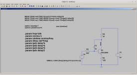
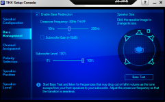
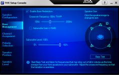
I think a Dirac enabled multichannel amp can run a fully active setup just by specifying crossover in the setup menu, yes? Alternatively I could use a minidsp or something similar, but I feel I do want Dirac.

Appreciate anyone who can throw any knowledge at me.

Those drivers, should I pounce on them, or am I an idiot for thinking I can just pick some decent drivers and make them work without fully understanding them.

I'm hoping to build something punchy, fast, dynamic. I currently have a very accurate, musical, pretty system which I love. Midrange magic. I thought I would go for a counterpoint, something a little faster and suited to rocking out. Yes, it is bookshelf I'm looking to build but in my experience a good bookshelf with a sub can give a pretty fun and intense presentation. And its what fits my space.

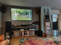
Pic of my space for reference. Yes the xmas decorations are down now 🙂

Attachments

  • IMG_20210201_170903.jpg
    IMG_20210201_170903.jpg
    982.9 KB · Views: 132

Safe commercial subwoofer low frequency extension EQ

My hypothesis is that much commercial (PA) equipment, when driven at much lower SPL, may be cost-effective for demanding domestic use. For example, an 18in JBL 2268H(PL) that is very low in distortion might be safely driven to a more audiophile low frequency limit. It's FR is 33Hz and my two specimens measure half power f3 of 45Hz. They already sound very nice crossed-over at up to 120Hz to compatible 2-way systems, adding impressive reproduction of double bass viols with C-extension (32.7Hz fundamental) and 40in orchestral bass drum. The question is, for use listening at ~16ft (5m) in a large acoustically treated home theater playing at SMPTE standard SPL (85dB nominal, 105 peak, ~108 maximum with all channels of low bass redirected, +LFE), could they be EQd safely and still with low distortion to say 30Hz or even lower?

FS: Tortuga DIY LDR Controllers, Displays, Buffers, etc

Selling 3 sets of Tortuga Audio V2 LDR control modules with JFET unity gain Buffers and display modules plus various additional components. Full Tortuga documentation available. I can also provide schematic and Eagle pcb files of the buffer which includes a delay-on. These were part of a working DIY volume control after a DSP crossover unit for biamping and triamping.

Sold: Set 1: Complete working DIY Tortuga V2 LDR prototype chassis with power supplies, two display modules, JFET buffer, Bybee Music Rails, and PS Audio power receptacle. $230obo. Sounds every bit as good as my new DIY Tortuga V3 DIY preamp. Needs Apple remote. Unit has no input selector switch. Inexpensive way to experience the great SQ of a buffered LDR volume attenuator.

Pending: Set 2: Tortuga V2 LDR controller, two display modules, JFET buffer plus power supply for Tortuga V2. $130obo. Needs Apple remote and buffer PS.

Set 3: Tortuga V2 LDR controller, one display module, JFET buffer and volume control encoder pot. $100obo. Can be used for biamping or Bal Vol with Set 1 above or for building a V2 LDR Volume controller by adding power supplies, etc. Can operate with encoder pot. Needs replacement LDR Module and both power supplies if not used with Set 1. Apple remote optional.

Tortuga Audio still sells new Apple remote control modules ($30+shipping) and encoder pots ($23). I can include a used Apple Remote A1294 from eBay and pair it and test it with the V2 LDR controller for an additional $20.

Buffers need PS such as the DIYINHK 4.17uV Ultralow noise regulator +-12/15V 1A plus a dual 15vac secondary transformer. Buffer uses no more than 60ma.

Attachments

  • Tortuga V2 Front.jpg
    Tortuga V2 Front.jpg
    39.3 KB · Views: 198
  • Tortuga V2 Back.jpg
    Tortuga V2 Back.jpg
    201.8 KB · Views: 215
  • Tortuga V2 Top.jpg
    Tortuga V2 Top.jpg
    336.8 KB · Views: 204
  • Tortuga V2 Set 2.jpg
    Tortuga V2 Set 2.jpg
    201 KB · Views: 207
  • Tortuga V2 Set 3.jpg
    Tortuga V2 Set 3.jpg
    135.8 KB · Views: 213
  • Tortuga V2 Buffer.jpg
    Tortuga V2 Buffer.jpg
    245.6 KB · Views: 134
  • Apple Remote.jpg
    Apple Remote.jpg
    28.9 KB · Views: 116

Bass guitar FET preamp

Well hi,

I have this Sadowsky/Aguilar based discrete bass guitar preamp schematic. It is designed for 9V but i want to run it on 18V for more headroom. Now, after i've built it and tested it, i have two questions:

1. Cause it's designed for 9V, it obviously distorts on 18V. What modifications i'd need to make to make it run clean with as much headroom as possible on 18V?

2. This circuit acts as radio receiver too for some reason and has some high pitched noise when Treble is turned up. I can hear stations on it with a lot of noise when signal is not fed with Treble boosted. Am i missing something? Proper shielding/grounding?

Thanks!

Attachments

  • FET bass preamp, Fender tone control.jpg
    FET bass preamp, Fender tone control.jpg
    182.5 KB · Views: 3,638

MTX Thunder 92001

The amp had a few shorted outputs on the high side so I replaced all the outputs, octocouplers and op-amps in output section. Under 12 volts of input I have rail to rail oscillation, once I crack the voltage above 12 volts rail to rail oscillation disappears and I’m left with the following image below. Powersupply functions like it should under or above 12 volts.

Attachments

  • 2CF69944-EB7E-4459-83A6-5BD4134EA00D.jpg
    2CF69944-EB7E-4459-83A6-5BD4134EA00D.jpg
    875.1 KB · Views: 103

Onkyo A7 conundrum

Hi

I have been working on an Onkyo A7. I have upgraded a number of these before and sorted out all sorts of problems, however this has me stumped. I have replaced all the electro caps and have the amp working- except if I attach a load (speaker or dummy load) to the output and then it draws massive current. At idle with no load it is about 0.2 amp which seems about right.

I have tested the output transistors and they seem fine (peak transistor tester), and as I am doing an upgrade on this unit I changed out all the main board transistors (all of which tested ok). There is negligible DC on speaker terminals. All the voltages on the main board measure fine

When I put tone in and test at the relay there is signal on both sides (input and output), and the relay works and the associated circuitry measures appropriately.

So I have been looking for cables issues, or anything else, but am I missing something basic?


schematic attached and all help appreciated


Peter

Attachments

Confused with speaker size + crossover

Good night,


I have a AV Receiver and I'm connecting it to my PC Soundcard (Auzentech X-fi Forte 7.1) in 5.1 using the Receiver 5.1 analog inputs (3.5mm to RCA).


I have the following questions:

Should I set my soundcard as Large\small speakers OR set it in the AV Receiver?;

Should I set a general Crossover for the 5 satellites in my soundcard and redirect anything below to the subwoofer, OR should I set the crossover in the Receiver?


ps: Attached pics show my soundcard with large vs small speakers (I can also set separately by each set of speakers like in the receiver).

Thank You
guily

Attachments

  • 1.png
    1.png
    151.6 KB · Views: 99
  • 2.png
    2.png
    152.7 KB · Views: 105

My next project is replacing/ upgrading capacitors in a Harman Kardon HK980

Hi.

My next project is replacing/ upgrading capacitors in a Harman Kardon HK980.
I pretty much have the amplifier boards down as to what to replace, but I am in doubt as to what to replace on the MCU board (schematics attached).

I also plan to replace the power supply caps on the +/- 15volts, 5volts and 12volts lines too.

HARMAN KARDON HK980 230 SM Service Manual download, schematics, eeprom, repair info for electronics experts

I hope some you brilliant guys have some ideas. 🙂

Attachments

  • harman_kardon_hk980_230_sm_Side_30.png
    harman_kardon_hk980_230_sm_Side_30.png
    206.7 KB · Views: 362
  • harman_kardon_hk980_230_sm_Side_36.png
    harman_kardon_hk980_230_sm_Side_36.png
    70.3 KB · Views: 288
  • harman_kardon_hk980_230_sm_Side_33.png
    harman_kardon_hk980_230_sm_Side_33.png
    35.3 KB · Views: 279
  • harman_kardon_hk980_230_sm_Side_37.png
    harman_kardon_hk980_230_sm_Side_37.png
    135.2 KB · Views: 303

The Accuton fix

Calling upon all residential loudspeaker engineers.

I am considering using the C25 tweeter and C90 midrange, but I am facing a dilemma. The diaphragm's are more or less on the same vertical plane when placed on a flat baffle. Nothing wrong with that per say, but it creates an interesting problem I would like to highlight and potentially get some input on. The issues is dispersion. I know first hand how a well implemented waveguide sounds and it is pure magic for the XO point and transition from midrange to tweeter. Since the Accutons are on the same acoustical plane, to time align the tweeter is never done. I've not seen any Accuton speakers with a waveguide and so, one run into the "issue" of loosing out on that extra level a waveguide offers.

The fix could be something like moving the tweeter and midrange to the woofer's acoustical plane, and give the tweeter a waveguide size corresponding to midrange size (5") and give the midrange waveguide size corresponding to the midwoofer size (6-7").

Anyone out there who have a similar experience or wana chime in ????

****************************************
(While writing this thread, I found one commercial company who did use waveguides with Accuton, namely Audiograde, but their website is for sale, so maybe the business is no longer operating.)

ECL84 triode strapped push pull line amp

Hello,
I want to build an ELC84 triode strapped (10mA, 250V) line amp using two CineMag S-217D output transformers with a primary of 12.5K (is that plate to plate impedance or just one plate impedance?).
The ECL84 pentode has an Rp of 3000 Ohms.
Is that a possible application for this output transformer?

Attachments

  • 3.jpg
    3.jpg
    39.1 KB · Views: 230

Wurlitzer 920 Schematic Needed

I have a Wurlitzer 920 piano extension amplifier from 1954 in the shop.

The circuit is not your average garden variety amp. The screen grids of the output tubes are connect to the cathode of a 6SL7, which appears to be connected to a socket on the edge of the chassis. Possibly some accessory plugs in there and completes connections to provide screen grid power, but until I can see a diagram, it's just a guess.

Anyone know what goes in that socket and better yet, anyone have a copy of the schematic?

Marantz SR1000 Recap

Hi,

It's been a while since I visited the site, as I haven't been DIYing lately, but now I need some advice.

Just this weekend I finished recapping an old Marantz SR1000, it had a decent sound, although it was never a showstopper. It had always been a good receiver (I use it on my pc), until a lot of the caps in the power circuit decided to blow up simultaneously. I bought exact equivalents for all except the reservoir caps, which I bought 50% bigger. Also recapped the amplifying circuit, with same value caps all around. Basically replaced old Elnas with brand new ones. It was a bit messy due to all the cabling to the two boards, lack of room etc. But got it done and it all works fine ..........

except that the highs are now noticeably harsh. Which was not the case before, although it was never on the sweet side.

I'm hoping it's just a "burn-in" issue, and am trying to give it some hours playing.

So, I have two questions:

1.- Would recapping have this effect in the overall sound of the receiver ??

2.- Is there any way to fix this, make it sound less harsh and more refined and sweet, even precise for that matter. If I were to describe the sound in terms of images, it sounds as when you set a picture in extreme sharpness, it goes wrong and feels unnatural.

Thanks,

Manolo

PMC OB1 clone

Does anyone know what 6.5"/170mm bass driver PMC uses in their OB1 speaker? It looks like it could be a Peerless 830946 or possibly a Morel HU631. PMC's web site says it is a doped 170mm driver with cast magnesium chassis. This would indicate to me that this is a paper coned woofer. Also, PMC seems to like using the Typhany Group's (Vifa, Peerless & Scan-Speak) drivers. Any suggestions? I have already selected the Scan-Speak R2904/7000 tweeter & ATC SM75-150S midrange and am now trying to pin down which woofer to use. Any ideas are more than welcome. I am using Martin King's transmission line tables to help out with the design. Has anyone used them before? They look like he really knows what he is doing.
Thanks to all,
John

MiniDSP 2x4 HD vs. new Soundcard and Equalizer APO for digital XO?

I have played around with Equalizer APO for trying out a digital XO for my speakers. But now when my new speakers are getting closer to being finished I need a good audio source for them. With my old speakers with passive filters I use optical out to my amplifier which has a DAC that does the job. But that option wont do with active filters since I need two amplifiers. So I am looking into which solution is the best one, at a budget.

Shall I go for a MiniDSP 2x4 HD? Seems simple enough to set up, get some room correction and FIR-filters. But I've heard that sound quality can't match a good soundcard or good DAC. Over here that will set me back 300€, and close to 100€ more if I go with an UMIK-1.
The other and basically free alternative is to make filters in Equalizer APO, as I understand it you can do phase correction that way too. But for that I need a new sound card, which puts me almost in the same price range as the MiniDSP-solution anyway. And maybe a mic aswell.
Which will perform the best? Will it be alot easier to get things working with the MiniDSP? Is software + soundcard inferior? I won't use any other audio source than my computer so I wont be held back by a software solution in that aspect.

I am reluctant to settle for old fashioned passive filters since I want to play around and modify my speakers. And as I understand it digital filters will for the most part get me better results, at least with my level of knowledge in filter design.

The whole reason I'm into DIY to begin with is to keep costs low. So I wont just throw money at the problem until it gets right. I want to get as close to my goal as I possibly can at my first try. :/

Transformer phase splitter rising frequency imbalance question

I'm testing some line level center tapped transformers today for how evenly they phase split a signal. I've never done this before so maybe someone can explain what I'm seeing. I'm using this transformer:

EDCOR - XSM Series

10k to 10k

I hooked the function generator to the primary and set the level to 1 volt. I hooked two channels of the scope to the split secondary so the scope shows the split signal very cleanly in perfect antiphase. Leaving the level the same I try out different frequencies. 1K, 5K, 10K, 15K, 20K...

Here is my question. As I stay below 15K the amplitude of the two phases is pretty much equal within 1%. But as I move above 15K to 20K one of the phases grows in amplitude over the other phase by a greater percentage.

Is this caused by the fact that the transformer is reaching its rated frequency limit? Or is it caused by the fact that a higher frequency is exposing maybe that 1 turn difference between the secondary halves? Or is it caused by core behavior at the higher frequency?

In any case the antiphase remains perfect, its just that at higher frequencies one side of the secondary grows noticeably taller on the scope.

Using this as a PP phase splitter would cause an imbalance at higher frequencies? There is not much musical content above 15K. Am I being too picky? I was expecting to see both phases stay identical in amplitude as frequency increases.

The Edcor transformer above is actually much better than some others I tested today. But they all exhibit this rising frequency brings on amplitude imbalance behavior. In fact one cheap radio replacement transformer I have started to show this imbalance as I approached 8K to 10K! This one (its a stepper-upper so maybe that makes it even more difficult to keep balance).

https://www.tubesandmore.com/products/transformer-audio-interstage-10-ma

Do you suspect a step-down splitter would probably not exhibit this behavior as much? I have not gotten to testing a few of those yet. I suspect they will maintain balance better just on a hunch, if so I'd probably want to use the
at as a PP phase splitter instead, then get back the gain in the driver.

OK I just tested the Edcor 10K to 600R. It exhibits the same behavior but not as bad, I start to see it begin at 13K but the percentage difference between the phases in amplitude is not nearly as far off as a step up or a 1:1 transformer.

PS80 - Small 80W darlington amplifier

Hello friends.

After a long time without posting due to work and other problems I bring a new amplifier that is still being developed and tested.

The PS80 darlington series is a small amplifier with darlington transistors at the output for a very simple purpose: to push my bass.

Simulator tests (the circuit is not yet definitive) have shown excellent performance at high frequencies as well, but I will use it to push my bass speakers.

I will still manufacture the pcb, 'tune' the amplifier and after that do the test using a QA401 audio analyzer, from QuantAsylum to better see the behavior of THD, IMD and the like.

Here in Brazil as always very hot and with good music !!! Hugs
(Paulo from PHS Audio)


Follows the provisional and still pending adjustment of values
esquema.png
View attachment PS80-NOVO-OPEN.pdf
PCB.png

ScanSpeak 10F

I have searched, and found to no avail, anyone who has used the Scanspeak 10F/8424G00 as a full range? or possibly with a helper tweeter.

I have only really found these threads, but no actual listening opinions.
http://www.diyaudio.com/forums/full...-driver-scan-speak-discovery-10f-4424g00.html
HTGuide Forum - Low Budget Speaker Porn
As a mid range, and not full-range-
http://www.diyaudio.com/forums/multi-way/193689-build-thread-ardor-point-source-monitor.html

I have been looking into some mini monitors for a specific application-
http://www.diyaudio.com/forums/multi-way/193917-4-mini-monitor.html
And a previous thread with my impressions of other Full Range drivers-
http://www.diyaudio.com/forums/full-range/190888-replacment-veravox-5s.html
More recent (enough output) from a sealed BB3.AL-
http://www.diyaudio.com/forums/full-range/188987-hobby-hifi-bb3tl.html

And its been suggested that a full-range driver might suit me better.

This is for low level listening, in a small 8ft square room. SPL Output/bass depth is not an issue.

Thanks, Rob

Source for crowbar circuit info?

Hi,

I have some radio gear that needs 13.8 VDC running off two linear PSUs. I understand if the voltage regulation fails then a higher voltage can appear at the outputs and burn up whatever is attached to the PSU.

I haven't been able to find a clear presentation of a crowbar circuit that shows how to calculate the component values for practical applications.

What are my options for building a black box than can go between the PSU and each radio?

If my question is too open-ended it is because I have been away from electronics for a long time and am getting back into it recently.

Thanks!

FS: Pair of RTP3 Platine Tube Preamp PCB

For Sale a a pair of the RTP3 Platine Tube preamp for sale. High quality pcb with for documentation (Schematics, detailled BOM, interconnect, etc). With these you can build the actual VSE RTP3 tube preamp, one pcb per channel. Each pcb contains everything for one channel, all power supplies, including the HV Shunt regulator, just connect the power transformers.

Very good preamp, probably one of the 10 top tube preamp, and one of the best for me, I have one. These pcb make building the preamp much easier. These pcb were a special order for one member but he changed his mind.

To complete the preamp you'll need the input source selector, and volume control. Take not ethat this preamp is full balanced, and that the original design was using one stereo source selector and one stereo volume step attenuator per channel.

If interested send me a private email.
SB

Attachments

  • IMG_20210122_134906.jpg
    IMG_20210122_134906.jpg
    998.8 KB · Views: 363

Hard vs Soft vacuum tubes, distorting more

The term came up and someone was posting information that I found questionable.

Terms used to describe the intensity of the vacuous space within a vacuum tube’s glass envelope. A hard vacuum denotes a more complete vacuum is created in the tube manufacturing process. Hard vacuum tubes – like the 6L6 and 6550 – have a higher saturation threshold and therefore distort less easily then soft vacuum tubes. Soft vacuum tubes – such as the EL34 or 6CA7 – have a less intense vacuum (sometimes called a gassy vacuum), saturate more easily and therefore break up [distort] more quickly. - Sweetwater
"What is tube "hardness"?"
"The tube "hardness" or "softness" - as you justifiably name itDijimiWrey - is narrowly associated with the degree of vacuum in the tube itself.

Tight vacuum tubes sound "harder" when clipped, have more headroom and attack, less compression, can afford more plate dissipation, and last longer because they hold their tolerance tighter over time. This is often the prerogative of military or industrial tubes if they have been suitably stored over time.

Soft vacuum tubes sound "softer" when clipped, less headroom and beefy punch, more compression and sensivity, but they widhstand less plate dissipation (beware red plating) and have a shorter life duration because their tolerances degrade faster over time.

In the early days of Radio, it was well-known that lower vacuum tubes were better for receiver detection stages (where more sensivity was needed) and higher vacuum tubes were prefered for RF amplification stage (where gain stability was required)."
First time I heard about soft and hard tubes. I looked it up and it sounded questionable to me.

I remember reading an Aspen Pittman article on how the vacuum within the output tube = degree of distortion. And thus the myth began...
So I am questioning the most knowledgeable bunch of tube geeks (if I may say so) that I know of. So is the concept true? Or is it somehow mistaking tube geometry somehow? Inquiring minds, you know how it goes.

How to wire high level inputs to Behringer amp for subwoofer?

Hello

I have a Behringer NX600D amp that runs two DIY VBSS 18" subs.
I have heard of the possible benefits for having the subs connected to the high level inputs (especially if focusing on 2 channel audio, which I am) and thus I wanted to give it a try.

Anyways I was hoping to get some advice on wiring and what I was thinking is:
Receiver --> A level / speaker outputs --> Speakers
Receiver --> B level / speaker outputs --> Behringer --> Subs

Question #1
The speaker outputs from the receiver had to be converted to an XLR input for the Behringer and thus I wired the positive to the positive xlr pin and the negative to the negative xlr pin and have nothing connected to the ground pin. Is that the proper way to do it? Or should one bridge the negative and the ground?

Question #2
The main issue that I am having is that the high level outputs are L and R and the inputs on the Behringer are also only L and R and there is no obvious way to combine the signal.
Thus sub #1 gets only the L signal and sub #2 only gets the R signal.

This is probably not too big of a deal, but it would be nice if the L&R signal could go to each sub.

So I was wondering should I just bridge the positive and negative B level outputs together and then run them to the L&R inputs? Or would this have any downsides? I know that one should not bridge the outputs and run it to a speaker as the load will be different and could blow the speaker/amp, but is running a bridged signal to the Behringer amp the proper way to it?

Any advice would be much appreciated on the wiring itself and also how to get both signals to both subs.

Thanks!

Trade-offs in loudspeaker design

Hi all,

I have recently became aware of trade-offs in loudspeaker design and couldn't find a thread about so here goes.

I've been reading here actively for past few years and somehow totally ignored/missed the importance of thinking through the trade-offs while designing a loudspeaker and I would have liked to realize it a lot sooner 🙂 I'd like this thread to help others to get the awareness early on.

A thread without content isn't very valuable so hopefully many members would share their thoughts. This is more philosophical subject than anything specific so I'm not sure if this thread leads anywhere. Anyway, here is my big insight.

There are some "main categories" of compromises in a DIY loudspeaker design project which in my view are cost, size, aesthetics, audio quality and having fun. Some decisions one have to make along a loudspeaker design process have trade-offs in more than one of these main categories. For example limiting the loudspeaker enclosure size might affect the bass extension, cost might limit options for the surface finishing and so on. I think prioritizing these main categories for a given project provides good basis for the decision making and gives confidence to successfully meet the project targets, or fail early if the project was too unrealistic. Ability to follow the set priority would define how many of the decisions, or compromises one was able to take, were actually good for the project.

Trade-offs seem to be everywhere and I find that being aware of their existence and what they are is very important for success of any project. IF one want's to make the best audio quality loudspeaker in the world, like many do, all trade-offs possible should be chosen from the cost, size and aesthetics categories and in this order. Trying to pursuit such project one should better be wealthy, have dedicated listening space and be blind which isn't fun at all so better relax from the goal a bit 😀 Now go and make the project you are involved successfully finished while having confidence on the decisions and lots of fun!

edit: I found out term "Designing from first principles" that would match what I'm trying to grasp here.

Adjust SMPS output voltage

I ordered two SMPS off eBay, pictured as below. They are labeled as +/-30v, but the actual output under 10ma current load is +/-39v and +/-33v. I have emailed the seller but got no answer so far. I'd like to find a way to adjust the output voltages, maybe by changing some resistors? Any one is familiar with this particular model?

Thanks!

Attachments

  • s-l1600.jpg
    s-l1600.jpg
    241.1 KB · Views: 374

Metrum Octave Dac - What are the Chips used

This NOS Dac which is causing something of a stir is getting soem very glowing reviews including in Hi Fi Critic. In all the threads and reviews I have read up to now there has never been a mention of the manufacturer or chip number that is actually used. It is often mentioned that it is not an audio but an industrial one used for other things. However it should still be easy to get the chip number and who made it ?

I mentioned this Dac to my audio repair engineer and he sent me an e-mail that they were using TDA1543 chips which I would find pretty hard to accept as these are nothing like what is being described and are just cheap replacements for TDA1541 chips.

Does anyone have one of these Dacs and have you looked at what chip is installed . Would be interested if anyone can shed any light on this.

Practice amp, single ended or push-pull?

Last time I made a guitar amp was 1975, and haven’t hardly played at all since then either. Time to get back into it! I want to make a small practice amp and I was wondering, would single ended class A be a better choice? I’m thinking of even harmonic production when you start to push it a bit. Only got a small handful of valves on hand, a 6DQ6A, two 6CA7s and a NOS 807. I’m leaning toward the 6DQ6A with about 120V on the plate. Not looking for high power output, just a setup that will ease into more “colour” as I wind the volume up. Low budget too. Any suggestions?

Signal bleed out of cathode follower and into phase inverter?

So I've got two amps on my desk right now that I've put together. One has a basic Sunn Model T style preamp, and one has a Marshall JCM800 style preamp. Both are push pull, although one's 4x6L6 and the other is just an ECC99.

Both amps use the phase inverter from this old ax84 document: https://ax84.com/archive/ax84.com/static/corepoweramps/20W_PP/AX84_20W_PP_Poweramp_Schematic.pdf

The preamps are of course somewhat different, but they both do have a gain stage with cathode follower right before the tone stack. Both amps have separate power supply nodes for the phase inverter tube and the gain/cf tube.

Both amps fundamentally work well, but in both amps, I'm having a problem where signal that seems to be bleeding out of the cathode follower and into the phase inverter.

It seems to be some kind of impedance node issue - from playing with various volume controls, it basically seems the higher resistance to ground there is on the preamp side of C13, the more signal bleeds in. Even if there is no connection from the output of the tone stack to the volume control, or i ground that out, the sound still bleeds through.

The bleed signal is bedroom volume loud, and very thin.

So, the signal is either bleeding through the ground, or bleeding through the power supply somehow. The grounding schemes are pretty standard, and the power supplies are standard as well, with a cap and dropping resistor for each node.

Have any of you guys seen something like that before? What would I do to solve it? I thought maybe I had made a silly mistake on the first amp, but the second amp is exhibiting the identical problem, so there has to be something design related.

Assemblage Power Amp

After building the Nobrainer power amp designed by Joachim Gerhard modded according to FdW ideas JG´s Nobrainer and Nobrainer Discrete - Page 33 - diyAudio I want to build a special version using a singleton input stage and double output devices so I can have more power and also verify the differences relative to the original opamp input.

Following Bigun work I asked his permission to use his input stage TGM8 - an amplifier based on Rod Elliot P3a - diyAudio

The resulting schematic sims ok but I would like to have the experts input regarding numerous doubts I have.

For reference I am posting the LTspice file as well as an initial schematic.

6 years ago I started this thread to develop a SE IPS power amp.

Now I am presenting the final evolution, the P200 model that uses Laterals on the output and a sziklai cascoded and ccs loaded on the input.

Attachments

Kef 104/2 speaker question

Hello all,
I have a pair of Kef 104/2 speakers that I have owned for 32 years.
They have been very well loved and taken care of, however, recently I am noticing some distortion, unwanted noise, coming from the lower midrange on one speaker.
Visually both mid range are pristine.
The foam donut on the lower woofer is "tattered", and I see I can easily fix that;
but I doubt that would cause a problem with the lower mid range?
Any suggestions?
I'm sure it's time to replace the capacitors, could this be the problem?
Thanks for your ideas in advance, Dan.

Cheap SA9027 + ES9023 (or PCM5102) DAC, anyone try?

Hello,

I'm looking for inexpensive dac. Found this
SA9027 ES9023 24bit 96kHz Asynchronous USB DAC HiFi Sound Decoder with Case | eBay
And DA3 SA9227 PCM5102A 32bit 384kHz USB DAC HiFi Asynchronous Decoder Case | eBay

They look like same but only dac chip is diferent. which one is better?

Another option is to make AMB "gamma2" dac and feed i2s with something like whis: WL High End CM6631A 7 Pin USB Daughter Card Free Shipping 1504A | eBay instead of 60$ AMB "asynchronous USB-I²S module".

+use external power supply.

Any advice?
Thank you

GB#2: Folsom EC7293: PVI Powered Frontend Amplifier, 60/120w 8/4ohm, 0.0005% THD

EC7293-glow.jpg

(Image of prototype)

The EC7293 uses 2 chip amps in parallel for high power with a discrete error correction frontend which reduces distortion; and has very low memory distortion. High sensitivity makes it perfect for a variety of sources with 8ohm and 4ohm speakers.

Input impedance: 27k
Gain: 32db
Distortion 1K; 8ohm; full power w/Antek AS-3225: <0.0005%
A short review.

At 8ohms:
EC7293-THD-8ohm-2.png


At 4ohms:
EC7293-THD-4ohm.png


EC7293-Amp-GB-PREVIEW-1.png


Board size: 6.25x2.25"

*****There is not a mirrored left/right set because it would screw up the feedback layout*****

Discrete front end: 4 transistors

PVI: The frontend uses a photovoltaic power supply for galvanic isolation of the signal path. It uses a G4 LED bulb with a current source to disable the onboard driver of the G4.

Distortion: <0.0005%

High power: These are running in "modular" mode so that they can handle a 4 ohm load with some dips, while providing substantial power with a max output current of 20A. The Antek AS-3225 is a great fit for 60/120w. More power may be possible if you follow the guidelines of the TDA7293 datasheet and make provisions with higher voltage capacitors, and larger heatsinks.

Terminals: Happy to say we've found some that are based on a copper metallurgy, that accept decent sized wire, and don't strip too easily (I can torque them pretty good with screwdriver) that the boards are made to fit, and I recommend in the BOM.

Input Capacitor
: This one is less sensitive to capacitors compared to the DIY7297. It has provisions for the same PHE426 and other caps. There is a slot-hole next to the pads so you can zip tie on larger caps and it has extra pads on the bottom to connect off board/long input capacitors.

CFC, smart PCB layout, & Copper Pours: Trace routing is optimized to improve performance and the power capacitors are placed for field cancellation (CFC); and copper pours are used for lower inductance.


dualpoleppv.png


Dualpole PSU PCB

Board Size: 4.25x3"

TO220 Diodes

CFC, smart PCB layout, & Copper Pours

Via holes for snap caps

RC and bypass: dampen the transformer & reduce noise


Suggested implementation with EC7293:

  • 18000uF to 24000uF per rail
  • Antek AS-3225 transformer
  • Keratherm insulators from DIYAudio store. (Chip tabs are 1.1” apart).
  • Heatsinks need to be larger than used on the 7297, nearly any enclosure with heatsinks for sides should work
  • 3U enclosure from DIYAudio store is a good fit. **
  • 2x Duapole's for dual mono with 2x transformers (Antek AS-2225)

**2U may work in dual mono with two smaller (shorter) transformers

Price & Amount needed to Print:

In order to print these up so I don't run out the day after, I'd like to see 12x pairs to get this going. To anyone that liked the DIY7297, this one is better, simply better.

EC7293+G4LEDR PCB $45ea (you'll need 2, to make a stereo amp)
DualPole PSU PCB $40ea

Shipping USA $8
Shipping International $16

And it will come with a BOM and some build details.

DeeJayBump 2,2
SAinet 2,2
shacketf 2,2
myl 2,2
mctavish 2,2
Stephen S. 2,2
jameshillj 2,0
drkingweeb 2,2
HaflerDh500Fan 2,2
genjamon 2,2
angchuck 4,1

Agilent/HP 82357B + HP 8903B + Pete Millett's tools / VEE runtime

Hi all,
Was wondering what Keysight/Agilent/HP VEE runtime program is everyone using under Windows 10? I can only get the VEE Pro 9.33 to install and it does seem to control the HP well, but I don't have $1k for this to be able to keep it past trial. This used to be free, as far as I know, and I'm just unsure what are the current options.

Secondly, is the Agilent/HP 82357B interface - which seems to be 100% genuine - supposed to come with the VEE program on it?

And, thirdly, any issues with Pete's tools running under 9.33? The VEE itself controls the HP perfectly well, but the programs were not doing anything. Just curious on the success rate there.

Thank you!

Wharfedale E30 crossover resistor value

Hi, a friend has c a pair of Wharfedale E30 speakers. The crossovers both have unidentifiable fried resistors. They appear large red resistors but a) no visible writing (blackened) and b) as both have failed, neither can be tested

Does anyone know the value of the resistor or have a schematic ?

many thanks

An externally hosted image should be here but it was not working when we last tested it.

Bradford console rebuild

Yes you read that right! I have used a soldering iron and have recapped a few tube amps and one Magnavox console as a retirement hobby. A family member asked if I could do anything with their old console (Grants store Bradfod line).

By default, I plan on replacing all of the electrolytic caps to try and breath a bit more ghusto into this very small but suprizingly detailed sound stage of this very under powered unit.

My observation thus far:

FM pulls in quite a few stations with solid sounding signal.
tape monitor plays well with bluetooth input.

My question is predicated on the fact that the FM signal indicator light grows dim when the volume as gained up. Is there something other than Cap replacement that may need attention?

thanks for any and all input.

NAD 1020 Preamp Problems

I am having problems with a NAD 1020 Preamp. The unit powers up fine and the 120V plugs in the back of the preamp also work as I can power a phono or CD.

The problem is that I get no output signal. If I turn up the volume all the way, you get some very distorted and scratchy thumps and pops that is generally coincident with the bass of the music being played.

I popped the unit open and there is nothing that looked obviously cooked.

Does anyone have any suggestions as to where the problem may be?

It does not seem to be a power supply problem. I fear that one of the transistors may be cooked in which case I doubt I would be able to track the bad one.

Any help would be appreciated.

Eminence NSW6021

3fl2773f31jc.jpg


Eminence has introduced a monster woofer and I wanted to see how it performs.

Q1GJR54.png


Here's how it performs in a QB3 ported box. There's a little bit of droop on the low end due to the low qes and qts.

MtnT3m8.png


The NWS6021 is an interesting driver. If you put it in a conventional enclosure it's challenging to hit xmax, because the driver just has a RIDICULOUS amount of displacement. There are plenty of 12" woofers with 21mm of xmax, but a 21" is unheard of. B&C iPal is the only competition I'm aware of, and it's much more expensive.

So I made this horn by juggling the parameters to push the F3 as low as possible and no further. Basically the idea was that if the F3 was 35hz or 40hz, the Eminence NSW6021 would *never* get close to it's xmax. (This assumes a high pass filter is in the mix.)

ePghvKI.png


24 cubic feet and an F3 of 22Hz. Five thousand watts of power handling. Yowza. 135dB of output.

Over at data-bass.com, the Zod Audio Maul rules the leaderboard, with four Rockford Fosgate nineteens. I think a couple of these Eminence woofers could likely beat it, for a fraction of the cost.

792D2Mx.png


Here's the response before filters

JagVKjX.png


Here's the excursion with and without filters. The filters are there to push the woofer right up to it's limits.

ha4V8nm.png


Here's the unfiltered response. This is kinda lump, admittedly, but I specifically pushed it lower than a conventional alignment so that I could use all of it's xmax. (If I'd used an F3 of 35 or 30hz, it wouldn't even get close to it's xmax.)

cKuL49a.png


Here's the model

PP Triode Choice & Output Impedance

I've been prototyping headphone amplifiers for some time now, using tubes I have on hand from TV pulls and whatnot. I currently have a more-or-less textbook 6FQ7 push-pull triode setup with a 12AT7 preamp and phase inverter. It's fed into a 10k:600 OPT and sounds good to my ear. B+ of 390v. Plate voltages and current are all in spec. I'm curious about its actual output impedance though. That OPT is almost certainly not ideal, the 600ohm secondary notwithstanding. I've attempted to learn how to figure it out, but so far it has eluded me. It'll get plenty loud for 98% of music out there, but I would appreciate a tad more headroom in case it's ever needed. I was looking online and found a good bit of praise for the 6H30. It has overall higher plate dissipation at 8W for both plates combined. The 6FQ7 is 4W each or 5.7W total. I've also read that the 6H30 has considerably lower output impedance. That being said, I have no idea what said impedance would be with two 6H30 triodes in PP. Can someone clue me in? Is it worth buying $70 worth of new tubes or should I look into a different OPT for what I currently have?

Please advice, JL Audio W7 for home use??

Hi all


Would you recommend and what result to expect if I use my car subwoofer CLS110RG-W7AE for home use as HiFi stereo and HT subwoofer??
I need only little help for my KEF R3 for stereo and aiming for bass quality not SPL.


It is original sealed JLAudio enclosure, I think 27 l volume but not sure


CLS110RG-W7AE - Car Audio - Subwoofer Systems - ProWedge™ - JL Audio


I was thinking on using Hypex 251 amp in separate small enclosure to drive it.
Room volume is 1525 cubic feet or 43cubic meters.


Driver specification:
Free Air Resonance (Fs)30.6

Hz Electrical “Q” (Qes) 0.578
Mechanical “Q” (Qms) 7.647
Total Speaker “Q” (Qts) 0.537
Equivalent Compliance (Vas) 1.28 cu ft / 36.1 L
One-Way Linear Excursion (Xmax)* 0.9 in / 23 mm
Reference Efficiency (no) 0.17%

Efficiency (1 W / 1 m)** 84.3 dB

SPL Effective Piston Area (Sd) 59.8 sq in / 0.0386 sq m
DC Resistance (Re)2.75 Ω


Thanks

Looking for help with a Dynaco FM-3

Several years ago I rebuilt/restored a Dynaco FM-3 with the singe board from the FM3Zone, it all looks OK, but it won't tune and only hear a faint sound. Anyone of have any interest in taking a look? I am willing to pay. I am not experienced with radio issues but have no way to tune first IF stage or determining if if other transformers are working correctly. I realize this has limited value but have already spent enough time and money and would like to see thsi through. '
Many thanks for looking

FS: Lii Audio F-15 15" drivers - NEW, pair

SOLD

New pair of Lii Audio F-15 drivers. These are 15" full range drivers.

$380/pair or best offer

One Pair | Recommended 15" Full Range Speaker Driver | Fast High and Scaled Sound | F-15 - Lii Audio, unique speaker, amplfier, quality and cost-saving parts for HiFi DIY

Prefer local buyer in Seattle PNW. Will consider shipping in continental USA.
No trades.

Attachments

  • IMG_6823.jpeg
    IMG_6823.jpeg
    189.2 KB · Views: 221
  • IMG_6827.jpeg
    IMG_6827.jpeg
    164.3 KB · Views: 221
  • IMG_6825.jpeg
    IMG_6825.jpeg
    156.9 KB · Views: 213

CV-1800 Repair Info

Re: Cerwin Vega CV-1800

Protection light is on in one channel. No obvious damage. The P/S seems good and the other channel works fine. This unit was returned to the CV depot twice in the past before the warranty ran out for the same reason. I found a "Goob" job of a resistor piggybacked with another resistor still in circuit for some reason. (I wasn't impressed with the quality of the "Patch" job)

Where might a guy find a repair manual? I'm very capable to do the repair but I want the biasing procedure and test point voltages..

Forgive me if this is in the wrong section. Thanks in Advance!

First stereo tube amp build advice

Hello all, newbie here.

I am contemplating building my first stereo hifi tube amplifier. I've been reading up on (guitar) tube amplifiers, watched way too many youtube clips and have (succesfully) built two guitar amps (Marshall JTM45 and JCM800). Despite that I find it hard to get started in the hifi amp world and that is the reason for this post.

I've got lots of question, but I'll limit myself to a few. Here they are: What amp do you guys suggest I should build? Are there any informative build threads or sites? Any must read books, articles or websites? I've read both tube preamp book by Merlin Blencowe and the power amp book by Richard Kuehnel.

Any advice is welcome. Thanks in advance.

Pair Anarchy Exodus 8 ohm woofers

SOLD Pair Anarchy Exodus 8 ohm woofers

Pair of Anarchy Exodus mid-woofers, like new condition. I used them in an audiophile system for two years in a tapped horn. 6,5 inch mid-woofer, excellent for tapped horn sub or in an easy two way speaker, 8 ohms impedance, 125 watts power, 35- 3000 Hz, U$ 66 each new. Sell a pair for U$ 75 or 95 CAD.
I live in Canada. Will split the shipping up to 15 U$\20CAD.

Despite the look on the pictures they are black.

Attachments

Pair Eminence Delta 10 A woofers

SOLD Pair Eminence Delta 10 A woofers

Pair of Eminence DELTA 10A woofers, like new condition. I used them in an audiophile system for two years and replaced them with some 8”, so am selling these excellent woofers. 10 inch high efficiency woofer, 8 ohms impedance, 350 watts power, 98.8 db SPL. U$90 each new. Sell a pair for U$ 100 or 120 CAD. I l'am in Canada. Will split the shipping up to 15 U$\20CAD.

Attachments

  • 20210131_143555.jpg
    20210131_143555.jpg
    476.4 KB · Views: 106
  • 20210131_143638.jpg
    20210131_143638.jpg
    762.1 KB · Views: 105
  • eminence Delta_10A .pdf
    eminence Delta_10A .pdf
    365.4 KB · Views: 55

[WTB] Looking for 6S4A tubes

Since I'm converting my Stax SRM-007tA from 6CG7 to 6S4A tubes, I'm looking for a couple of the latter (6s4a).

Quads of 6S4A would be ideal, like actual matched tubes or matching date codes.

In order to provide something nice to look at, I've attached some pics of the ongoing conversion 🙂

Attachments

  • Q7w20ro.jpg
    Q7w20ro.jpg
    835.1 KB · Views: 203
  • wViDsgz.jpg
    wViDsgz.jpg
    887.9 KB · Views: 214

NAD 3020A phono output and new caps

New My NAD 3020A, with no turntable connected, has a loud "hiss" when 'phono' is selected, but all the other outputs are super quiet.
Any suggestions as to what would cause this?


Also, thinking of replacing the four main power supply caps with either Panasonic FC cap, or Nichicon KW or FW.
Would appreciate advice on this choice, and is there anywhere other than the big suppliers who supply authentic caps in the UK without high delivery or minimum order prices?

recycle and drill holes

I put the new faitalPRO 3FE25 ("mud" cermet) 3" on the ~middle of the centers I cut out of my homey style 11 cu ft Stereo subwoofers (two 12" SB woofers in one big box. The only approach no one wants to attempt is one big box... 24"x25"x31" of BB 1/2" glued by WoodTiteIII.

Seems to work. The cascading crescendos in "Pines of Rome" by Ottorini Respighi brought tears to my ancient eyeballs. I never thought I could enjoy that monster in any place I could afford to live. Damn. I was SO young. once.

I am 73 and live in a tiny one bedroom apartment with my wife. We have two big windows, facing north. In Texas, that is the only way to survive "Texas weather". Snowstorms and hurricanes. Not on the same day, as a fool's rule.

Sound great through 5 each 1/2" holes that allow the drivers to breathe.

There are new Swiffers Heavy Duty on the back side of the 3". five 1/2" hole on the front sides.

Sounds much better than the drivers just interspersed with random Maple blocks. Mini city scape...

Soekris DAM1021 with Audiozen mainboard & Amanero

SOLD -Soekris DAM1021

For sale in perfect condition and working order:

DAM1021-05 - REV3 0.05% resistors upgraded with VREF caps.
Audiozen Mainboard fully built with Amenaro USB.
Audiozen display and encoder -

NOTE: while taking the DAC apart for the pics it seems I have damaged the ribbon cable for the display, now it doesn't light up. The DAC works perfectly well without the display and encoder except it is locked to USB input and max DB volume. A new ribbon is all that is needed.

SOLD

Attachments

  • IMG_2408.jpg
    IMG_2408.jpg
    175.8 KB · Views: 368
  • IMG_2409.jpg
    IMG_2409.jpg
    142.3 KB · Views: 365
  • IMG_2411.jpg
    IMG_2411.jpg
    156.5 KB · Views: 363

A&R Power Amp RV setting for opamp

Hi guys, need some help. Just got a working A&R SA200 power amp.

I noticed that a previous owner had probably exchanged the +ve and -ve fuses with M4 screws (as you would..) and burnt the rail resistors and the pcb itself. Someone repaired it.

It is working on that channel but I found that RV3 for the clip indicator is totally differently set in each of the identical channels. Whilst the one in the unrepaired channel is fully open (0.8ohm) the one in the repaired channel is set to 75k.

I am going to recap the amp and want to adjust but could do with some gudiance how this clip indicator circuit works and wha to set things to. Arcam are always good and helpful with schematics and I can find my way around their drawings but just lack the essential knowledge to work things out sometines.

The IC is an RCA 1458, the amp is from 1981 or thereabouts, it is a nice dual mono layout with proper discrete components in it.

I attach the schematic here, it's also available from HiFi Engine.

Any help, especially explaining how this part of the circuit works would be very welcome.

Many Thanks

Attachments

Projects by fanatics, for fanatics
Get answers and advice for everyone wanting to learn the art of audio.
Join the Community
507,830
Members
7,889,986
Messages

Filter

Forum Statistics

Threads
406,334
Messages
7,889,986
Members
507,830
Latest member
LouisAtLarge