Mid 70's amp distorting pretty badly. High crazy base voltages 20v¿?

Hi. I got an old amp from the mid 70's that I'm trying to fix. The fuses were gone and so some tiny bulbs which illuminate the front. The switches need deep cleaning in order to get some sound of it.

The thing sounds and pots work ok, but it distorts very badly. At low volumes is ok, but it starts to distort pretty soon.

It uses a couple of BD131 and BD132 as output stage transistors. The voltages are odd. Here they are:

BD131 (NPN)
  1. 21v
  2. 32v
  3. 21v

BD132 (PNP)
  1. 21v
  2. 0v
  3. 20v

The amp is fed with 32v DC. It's a 2x12w at 8ohms.

My knowledge is quite limited, but assuming this is a class AB complementary amp, base voltages are crazy. And if I'm not wrong, we should be expecting a lower emitter voltage as well. Something around 16v.

There are a few resistors that are pretty hot. You can touch them for about two seconds, then it hurts. Couple of them are "tanned". They read the correct value, but you can see they suffered at some point. There's one of them that drops the voltage to 21v to 0.7v...

I replaced the output transistors and all electrolytic caps with no luck. Where should I be looking at? I'm lost

There's a trimmer right at the supply voltage. It's set so the voltage drops to around 19v. At max. it drops the voltage to 16v or so, no more.

There's obviously something very wrong. Transistors are biased at really high voltages. I can't understand what's causing such levels. It happens to both channels. Right now I'm focusing just in one of them since they behave the same.

There's no schematic so I'm going to make a sketch of output stage core. The core are the couple BD131 & BD132, a MC150 which feeds the BD131 and a SC107B. The latter is handling 32v at one of its legs...

I appreciate any help, thanks.

Speed control using low frequency phase correlation.

Given that a record has a cyclic low frequency wave(s) that are below the standard frequency used for audio. Could it be possible to use a low pass filter and then sample the low frequency using an ADC. Then use FFT phase correlation to essentially match the cycles of the record as they're playing and correct the speed of the record?

You're not sampling or correcting the record playback via digital but rather using the record noise to correlate (note that phase correlation has decent noise rejection).

Focal Elear Headphones perfect condition

Maybe someone here would be interested, also on the bay but at good discount here for the DIY family 🙂

The very best headphones under £800 or more, I love these and is a reluctant sale but I have bought some Stax, so need the funds.

Absolutely perfect condition and working order, still under warranty, I am the second owner. These were bought 2020 and have been kept mint in a case when not used. Fully boxed and with original shipping carton.

Selling for £500 plus shipping

Attachments

  • IMG_2718.jpg
    IMG_2718.jpg
    978.1 KB · Views: 137
  • IMG_2722.jpg
    IMG_2722.jpg
    970.9 KB · Views: 129

Advice about sound cards please !

Hello guys, I hope I'm posting in the right place, it's the first time I write something on this forum.
I have a friend who would like to connect its UMC404HD to a pair of passive loudspeakers, wich are 2 Infinity Primus 150.
I've done some research and here's what I found :
connecting directely the passive loudspeaker to the main output (either XLR or 1/4" jacks) will work but will damage the sound card in the long run.
The solution is to use an amplifier between them.
I've chosen this one : AIYIMA A07 Amplifier Stereo Class D TPA3255 2x225W 4 Ohm - Audiophonics
Here's how I think of it :
I'll make him a cable wich goes from his jacks main outputs to the RCA of the amplifier (so I need to make 2 Jack-RCA mono cables) and I'll just make a regular loudspeaker cable from the amplifier to the loudspeakers.
What do you think ? Do you see any flaws ?
My main concern is I'm not sur about the main line output going into the RCA input of the amplifier.
Thanks in advance.

Fell lens

Hi guys.
My CD Recorder Pioneer stopped working.
After disassembled it, I found that the laser lens rolled into the box.
Obviously fallen during transport.
Is it possible to fix with glue or something more is needed?

Cheers

Attachments

  • DSC_12166---.jpg
    DSC_12166---.jpg
    780.6 KB · Views: 117
  • DSC_12146_cr.jpg
    DSC_12146_cr.jpg
    297.3 KB · Views: 105
  • DSC_12151_cr.jpg
    DSC_12151_cr.jpg
    371.8 KB · Views: 105
  • DSC_12154_cr.jpg
    DSC_12154_cr.jpg
    334.7 KB · Views: 126
  • DSC_12172_cr.jpg
    DSC_12172_cr.jpg
    305.1 KB · Views: 116

Troubleshooting a Dynaco ST-35

I was demoing some new-to-me speakers (8 ohm, not a difficult load) and was using my Dynaco ST-35. It was playing fine for awhile (10min?) and then the music stopped and I heard a hum and I turned off the amp. Smelled a little smoky smell.

I took out the amp, opened it up, inspected inside and couldn't see anything particularly wrong. So I put some dummy loads on the speaker outputs and turned it back on upside down so I could see if anything obvious was happening.

Turns out the 50ohm/5W (R12 in schematic) started smoking, so I quickly turned it off.

I measured the main power supply capacitances C8A, C8B, C8C, C8D. C8C and C8D measured as the implemented parts indicated. C8A and C8B measured significantly higher than expected. C8A should have been 40-60uF but measured about 160uF. C8B should have been 20-40uF but measured more like 260uF.

Came back a few hours later, and now C8A and C8B are both measuring about 80-90uF (still higher than expected, but lower than immediately after I powered down the amp).

Any idea why R12 would start smoking - I mean there must be very high current flow through there, but C8B wasn't shorted to ground or anything.

Haven't tested the tubes, output, or power transformers, but everything was working for 10min or so.

Just looking for suggestions on where I might start looking for problems given the symptoms.

Thanks.

ST-35-Schematic.jpg

Has anyone tried SEAS U16RCY?

Choosing the drivers for the next project is the most intriguing part of the diy procedure.
This time I am looking for something small and I want to try a seas driver since my previous attempts were with sb acoustics and I would like to try something else.
I've seen two nice projects from well respected designers in the diy community, the one is the seas curv by troels Gravesen and the other is the prestigious monitor from gornir from audio excite. Both are promising but I am not sure about the seas u16rcy. I've seen some measurements at audio excite and the u16rcy distortion is much worse than the sb15/sb17.
Should I stick with the sb acoustics or give it a shot with the u16rcy?
Has anyone worked or listened to u16rcy?

Beginner project: TA7630P + TDA1557q

Hi all! New member here.

I'm an electronic beginner, and as a first analog project (until now I played with arduino and similar) I wanted to make a simple chip amplifier with some controls.

I managed to find a TDA1557q and a TA7630P.

So, I breadboarded the TDA1557q sample circuit from the datasheet and the TA7630P sample circuit, also from datasheet (single power supply one).

The main problems are two:

1. When i plug my phone aux into the TA7630P circuit the output volume is really low, instead, when i plug the phone directly in the amplifier, is much higher. I read something about audio buffer, it can be that?

2. When i connect the TA7630P circuit with the TDA1557q one I hear only noises and I am able to hear some music (low volume) only by placing a 470ohm resistor to ground before the input cap

I've been working on this two chip since two weeks, I'm running out of ideas. 🙁

Any help would be appreciated, thanks.
I also uploaded some photos.

Attachments

  • TA7630P.jpg
    TA7630P.jpg
    731 KB · Views: 197
  • TDA1557Q.jpg
    TDA1557Q.jpg
    629.6 KB · Views: 193
  • TA7630P_TDA1557Q.jpg
    TA7630P_TDA1557Q.jpg
    698.3 KB · Views: 182

Pete Millett High Voltage Power Supply- Need help

Hey everyone,

New member here, hope this is the appropriate forum to post this. I made sure to search first, but didn't find any topics pertaining to my issue.

I recently built Pete Millett's hv bench power supply ( High-voltage bench supply ) and am having some trouble getting B+ voltage. I have filament voltage and negative bias voltage, but had -
6v on the B+ out. After tracing my work and comparing it to the schematic a few times, I'm 99% sure that my wiring is correct.

I contacted Mr. Millett directly for advice on what I may have done wrong. He responded promptly and told me that he didn't see how the circuit could work as drawn, as the error amp plate (V5 pin 7) should be connected to B+. He suggested I connect the 330k resistor in the schematic at the current limit circuit from pin 7 to B+. This gave me +.4v and some current meter swing when playing with the 100k pot, but nothing more. Unfortunately, he said he may have found the problem after he uploaded the pictures to the web page and corrected it later, however that was 15 years ago and he no longer has the unit.

I'm curious if anyone here has built this supply and run into a similar problem? How did you correct it? I'm learning tube circuit design, but I am in no way experienced enough at the moment to figure out why this supply isn't working without help, so if anyone has any ideas on what could cause my issue (assuming it is a design flaw and not just a wiring error on my part), would anyone be willing to take a look at the schematic in the link above and make any suggestions? I spent months building this and I'm not quite ready to give up on it, but I'll admit I'm getting close.

Thanks for any help everyone,
Daniel

Camper system

I am planning a camper conversion and thinking about the hifi. I have alpine components that can go in the front doors and a rockford sub but I want something with a bit more finesse for the living space.

My thoughts so far to get an even sound all through the back would be a line array with small drivers running from rear doors to the cab along the ceiling. This could also be used to compliment the front door speakers while driving.

Does this seem feasible or any other ideas please?

2-way crossover with 15WU8741T00 advice needed

Hi to all. I am very new in DIY, but decided to make Scanspeak Lumine, as heard it at Youtube and was impressed by their clear sound. But as i already have 8-ohm tweeters (the ones from Sony ss-g55, 8 ohm, biocellulose), and decided to use 8-ohm version of SS 15WU8741T00, instead of 4-ohm 15WU4741T00 (mainly to avoid different impedance of tweeter and woofer). It seems that it will be something very different from the Lumine, but I hope that the woofer will give a good quality sound. Followed instructions in "Introduction to designing crossovers without measurement " thread, and made calculations, so I ended with the crossover shown. Can someone explain what is the role of R3 and L2 in the original Lumine crossover, and give advice on this crossover in general? Thanks in advance.

Attachments

  • Lumine-1-Schematic_a.png
    Lumine-1-Schematic_a.png
    13 KB · Views: 628
  • Crossover network new.jpg
    Crossover network new.jpg
    34.2 KB · Views: 549

Help to upgrade crossover

Hello, I have Troels Gravensen loudspeakers, specifically the Jensen ATS model. Jenzen-ATS
Made some changes such as improving or, if you prefer, adjusting to my sound tastes, various caps of the crossover. Seeing the changes that choosing one cap or another can generate, especially those dedicated to high frequencies, I wonder if this is also important in the choice of coils. The cut-off on the ATS is at 2200 hz. Therefore, there is an important area of ​​high frequencies that correspond to the mids speaker. The ATS works with a second order filter and uses a Jantzen model WAX 1.8mH, 0.37omh and 14 AWG coil in the mids section. My question is the following. Could you improve the sound by replacing this coil(respecting the original values)? If the answer is "yes", what makes and models can be suggested?

BR
Toñi

Active Speakers - Dual USB DACs - How To Synchronise USB Output

I've been considering an active speaker project, motivated by the advent of low cost high quality amplifiers (TDA32xx)
I'm coming up against the challenge of low cost computer output to multiple amps

In an ideal world I would use
  1. Source = AMLogic S9xx or Pi or Nuc, running some flavour ofLinux
  2. DSP = CamillaDSP or BruteFIR or similar running on source computer
  3. DAC = USB DACs eg. Topping E30 * n
  4. Amplifier = TPA325n * 2-3
  5. Speaker = 2-3 Way without crossover (handling by computer)

Most of those elements are low cost, "good quality" and sufficiently capable

The Problem
USB is a negotiated link, so there can be significant timing variance between transmissions and between devices. This will probably be an audible problem when "sound" timing needs to be coordinated across multiple devices ie. the DACs when one is feeding left speaker an another DAC feeding right speaker, say​

The Question
Is there a way to guarantee trasmission coordination across multiple USB devices ? Has anyone succeeded in making this kind of setup work ?​

It's possible to purchase additional equipment to achieve this outcome (but these add to the cost and add points of failure) eg.

  • 8 Channel DAC like the Octo or DIYinHK units
    Intermediate processor like the Motu 8A or Auverdion Aurora/Infinitas
    MiniDSP UDIO8

Is there a way to achieve this outcome or am I misunderstanding or looking in the wrong place

Any advice / guidance gratefully accepted

"Grounding" LM 3886 (and other chipamps

I have read through a number of threads about the LM 3886 and the design of the PCB to mount it on. One much discussed point concerning the grounds on the PCB´s concerns the power ground and the large currents going through it and the possible problems of havoc that can be caused by this if done wrong.


Most of these designs have the same or a very similar sequence of connections on the edge opposite of where the LM3886 is mounted and which is , from left to right : negative rail , ground from psu , positive rail , then speaker out + and speaker out - , and then the input and its ground.


So forgive me if there is some error in my reasoning and explain why , but based on my long years as a tecnician and working with discreete amps mostly ,what speaks against forking the input ground trace going to the center of the caps adding the speaker out ground there ? This would change the sequence of connections as follows and would keep the high currents completely away from the rest of the PCB , along with the associated problems ? And all other grounds remain as were....


Sequence then would be from left to right : negative rail , ground from psu , speaker out minus , positive rail , then speaker out + , and then the input and its ground. As is done mostly with high power discreete amps the speaker ground then returns directly to the juntion of the filter- caps . Board size stay the same and could possibly be further optimized. I cannot judge that as I have no experience with it except of what I learned reading in all the threads.

If I am , for whatever reason , wrong please correct me Thanks Michael

elac design flaw lm3886?

Hi.
I been helping out and repairing several elac active speakers.
they have a lm3886 which amplifing the tweeter and tip41 and 42c for the rest,
there is also a tda180 circuit which i dont really understand,
but the problem is that the resistor gets really hot connected on the negative rail to ground.
also had a lot of capactors bad which is replaced.
the negaive vee supplying the lm3886 and tip42 plus tda180 which connect directly to ground with a 2w 500ohms resistor. get burning hot, and it measures 25 volt over it.
I looked at other circuits but cant see any using 500 ohm, on the postive side I measure 9k ohm to grund.
any idea?
best regards after midnight in norway...

Niklas.

Attachments

  • lm3886.jpg
    lm3886.jpg
    272.4 KB · Views: 1,147

Fairchild 670 Drip Time Constraint PCB's

Hey Everyone I need some help

I purchased a Drip Electronics Fairchild 670 board back in 2013 for $400usd. I received the board from Gregory at Drip, but he forgot to include the Time constraint Pcb's in the order. I have been asking him for the missing Pbc's for almost 8 years now, and he always fails to get back to me, or says he'll take a look with no follow up..... I guess i'll just go **** myself then..... (sorry my rant is over) :redhot::redhot:

I'm at the point where I have to get them printed myself from another company to finish this build. Anyways I thought I'd turn to you all. Does anyone have the time constraint pcbs, that can send me a picture. Or possibly a schematic for the time constraints. Anything would help at this point.

Thanks for your help

OTL tubes amplifier based on the ecl84

Who said tubes amplifier had to be warm and lush ? This one certainly isn't 😀 I've got a prototype of this amplifier working on my bench and it has serious slam.

It is based on conventional building blocks: mu-follower for the gainstage, white cathode follower for the output stage. The little triode in the ecl84 has some serious gain, which compelled me to use a relatively heavy feedback to take the gain down. The trioded pentode sections are run pretty hard at 170V and 25ma each. The tubes aren't very expensive but I'll try to run the amp a bit colder in the long term (something like 160V, 23ma). Into a 300ohms load (headphones in mind are AKG K340, senn HD600), it translate into more than needed power.

All the coupling caps are mkp, resistors are a mix of 2W and 0.6W metal film, depending on position (and applied voltages).

attachment.php


The power supply is coming straigth from tubecad's website, with a small twist to use 200V rated caps on a 380V supply. The heaters are biased somewhere around 90V. I use AC and it's silent (no hum) with high impedance headphones.

attachment.php

Attachments

  • Capturer.PNG
    Capturer.PNG
    41.2 KB · Views: 2,279
  • Capturer2.PNG
    Capturer2.PNG
    26 KB · Views: 1,527

Kinergetics Chiro C-500 Amp problem

Been trying to restore this 5-channel amp for a while, BUT the main power PCB has several missing traces (delaminated and gone bye-bye. No schematics seem to be available.

If anyone out there owns one of these amps and is willing to take a few photos of this PCB, I'll be able to have a working amp. Would be happy to pay you for your time & efforts! It is pretty easy to get to and I can give you some simple instructions on opening it up.

Thanks!

Ivan

Jose Duddy New Member

Love Android and Google. Installed new car headset Android 9.1. I am a singer and entertainer and Android is my hobby. 26 wifi philips light bulbs. 5 google minis, 1 google hub max, 1 original google home. 3 google chrome cast 4k, 1 nest doorbell, 1 outdoor nest cam, 1 nest thermostat, 1 Nest X Yale door lock. Needless to say I have built a google eco system...lol.

Thanks to everyone.

Please direct me to a forum to discuss Android Car Headset, and installs and upgrades.

Android car headset 9.1 - Google Photos

Why do these B&W metal domes sound so good?

I'm trying to understand why these B&W tweeters don't have that typical metal dome harshness? They sound alot like planar drivers with very detailed upper top end and never ever get nasty even at very high volume levels. I usually can pick up on the ultrasonic response peak by ear listening to the upper piano notes or cymbals but these things don't sound like they have any breakup mode even though they should. I don't have a good enough measurement mic that has the frequency respose to measure that high where that peak usually resides. Maybe the acoustic lense has something to do with this, suppressing it?

I have the same tweeters in my B&W DM580s. They have better midrange and top end than some $5000 speakers I've heard. I'm baffled by how much dynamic reserve these things have being a 2.5 way design. They are crossed over fairly high around 3.5k 3rd order, so that probably has something to do with it, plus they can play as loud as some larger 3 ways. I did rip out all the old electrolytic caps and installed PP caps which made a massive difference everywhere.

So I just wished I knew the secret to why these tweeters are so good. I have a pair of Thiel tweeters made by Seas that sound similar, but not as open and dynamic. I used to turn my nose up at metal domes, but these B&Ws converted me.

Attachments

  • 20210306_023839.jpg
    20210306_023839.jpg
    1,012.1 KB · Views: 960
  • 20210306_032014.jpg
    20210306_032014.jpg
    352.5 KB · Views: 881

D Class IC amps, are they safe without a heat sink?

Hi,
I'm new to this so please forgive my noob questions


I'm building a ported boombox style speaker from ply with all my components boxed in. I've had a D Class IC amp in the past with a heat sink, it was only 15W per channel but it got really hot! I placed it near the ports so it got good air movement and everything seems fine.


But for this project I'd like to build something 50W per channel with D class IC amp but a lot of the suppliers don't have a heat sink attached and I'm wondering if I need to attach my own? Can I place it near the ports without a heat sink? Or is it just fine to box it in a separate compartment and forget about thermal management all together?

Thoughts?


Thanks 🙂

PINK TRIANGLE PT TOO PSU PROBLEMS

Dear DiyAudio:
I got a PT Too for trade, but with issues. The last owner told me that it didn´t work, and I have now taken it apart.
It works, although not properly.


I know this doesn´t fix the bug, but:
-all electrolytic´s replaced
-rectifier replaced


Just to be certain the problem isn´t there.


But:

When trimpot on the right is turned to max and the trimpot to the left is turned to min, the motor runs quiet and as it should on 33. But when switching to 45 the motor just vibrates, not turning. When turning the left trimpot clockwise to 10 o´clock, the motor runs as it should, but now it just vibrates on 33. I have measured the two voltages at the motor (33/ 45) and it´s aprox 90V and 107V (when adjusted to the right speed with trimpot left). So the problem is that it´s not possible to adjust the trimpots to work on both speeds.
Anyone familiar with this?
Thank you in advance!

Attachments

  • IMG_3498-1.jpg
    IMG_3498-1.jpg
    671.2 KB · Views: 156
  • IMG_3499-1.jpg
    IMG_3499-1.jpg
    886.4 KB · Views: 129

Reverse engineering of famous chassis

Hello, everyone,
it all began at my friend’s request to do the CAD model and detailed drawings of the Audia Flight Strumento N1.
Over time, I’ve done the same for several chassis (Goldmund Telos, Vitus 103, D’Agostino Relentless, etc.) and Kyron Kronos body.
Some of them are adapted to the use non-original components (Strumento’s buttons, Kyron’s tweeter and mid-woofer) but otherwise my models are exactly the same as the original.
A few images of projects and, particularly, their realization, could be find below.
So, I can create 3D models, containing complete details and fastenings, of famous or less-known 😉 chasses. Having a model and drawings, you can produce them in any workshop.
I must add, reverse engineering doesn’t infringe anyone's copyright.

Attachments

  • AUDIA Chassy.png
    AUDIA Chassy.png
    341.4 KB · Views: 472
  • Audia detales.jpg
    Audia detales.jpg
    895 KB · Views: 475
  • Audia Flight.jpg
    Audia Flight.jpg
    24.7 KB · Views: 477
  • D'Agostino 2:3.png
    D'Agostino 2:3.png
    505.2 KB · Views: 463
  • D'Agostino back.png
    D'Agostino back.png
    414.7 KB · Views: 479
  • KYRON 3:4.png
    KYRON 3:4.png
    271.4 KB · Views: 205
  • KYRON .jpg
    KYRON .jpg
    192.3 KB · Views: 193
  • GOLDMUND.png
    GOLDMUND.png
    370.9 KB · Views: 209
  • VITUS.png
    VITUS.png
    238 KB · Views: 190
  • VITUS 3.png
    VITUS 3.png
    286.8 KB · Views: 178

NOS tubes for sale VT25, 6V6

Hi there,

I am selling the following:

Pair of VT-25, NOS in original boxes. Asking $140.

Pair of Jan-CTL_6V6GT/G. NOS in original boxes. Asking $80.

I will ship to USCON only for $15.

Attachments

  • IMG_6799.jpg
    IMG_6799.jpg
    395.1 KB · Views: 175
  • IMG_6800.jpg
    IMG_6800.jpg
    959.3 KB · Views: 174
  • IMG_6801.jpg
    IMG_6801.jpg
    874.1 KB · Views: 158
  • IMG_6802.jpg
    IMG_6802.jpg
    297 KB · Views: 153
  • IMG_6761.jpg
    IMG_6761.jpg
    380.2 KB · Views: 157
  • IMG_6762.jpg
    IMG_6762.jpg
    340.2 KB · Views: 63
  • IMG_6763.jpg
    IMG_6763.jpg
    283 KB · Views: 56
  • IMG_6764.jpg
    IMG_6764.jpg
    262.2 KB · Views: 60

Free To Good Home

XKi for W5-2143 free to good home. I threw this together a while back and never did anything with it. Have not cut wings yet but everything else is done. Even lined with 1/2" felt. Would prefer DIYAUDIO member in DFW Texas area to pickup off my front porch so I don't have to ship. PM me if interested. Thanks.

Attachments

  • IMG_0014.jpg
    IMG_0014.jpg
    103.9 KB · Views: 500

DIY 12V Car audio power supply - troubles

Hello everyone!

It is the first time that I publish in the "power supplies" section.

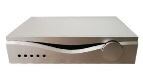
I am building a switching power supply to be used in the CAR AUDIO field, feeding it from the wall network, obtaining an adjustable output voltage from 12.4v to 14.4v (and beyond).


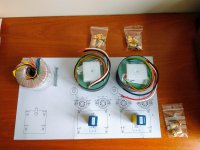
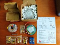
I made a project from scratch.

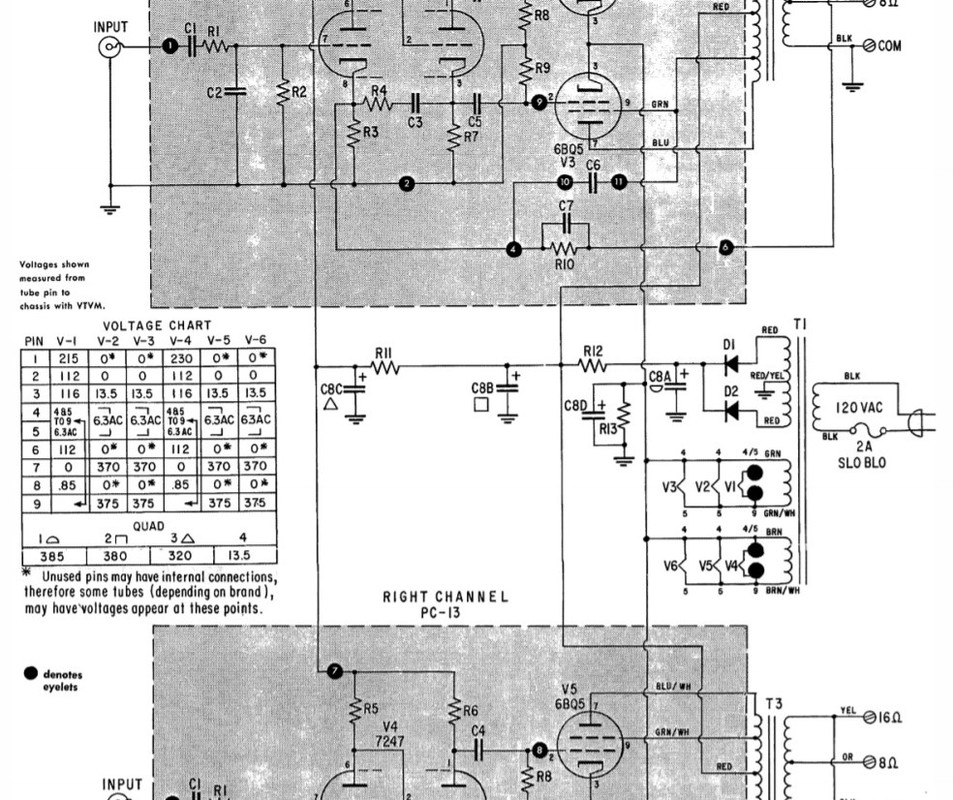
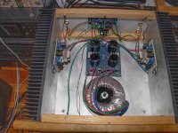
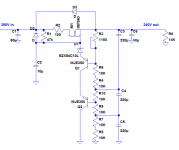
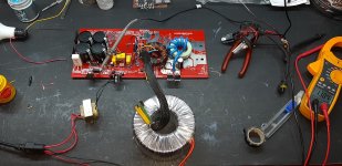
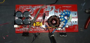
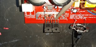
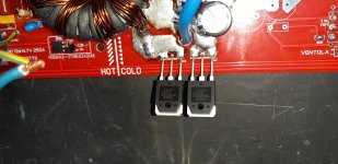
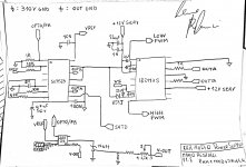
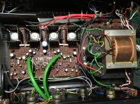
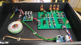
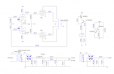
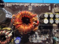
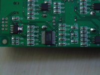
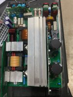
The power supply uses the SG3525 PWM controller which drives an IR2113S driver which in turn drives a pair of very powerful IGBTs.
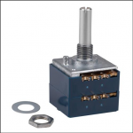
The power supply is regulated, and keeps its output stable even when we are absorbing almost all the deliverable current (or at least it should) and through a potentiometer that adjusts the reference of a TL431 which in turn drives the LED of an optocoupler, I get voltage regulation and setting.


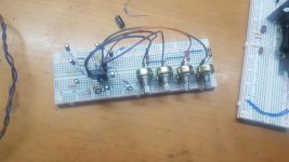
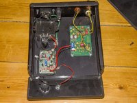
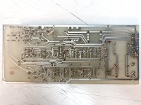
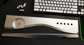
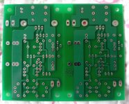
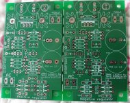
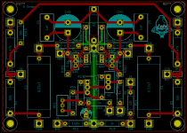
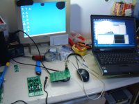
I made the PCB and installed the main components to start testing it, currently I have not installed the protections (short circuit and thermal) because I was interested in knowing if at least it did its primary job (produce enough voltage and current as I thought it would).

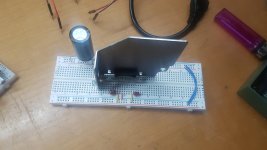
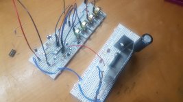
After doing everything, instead of immediately using the direct electrical network, I used a transformer to isolate myself from the electrical network and obtain a lower voltage to avoid disastrous failures, in fact, with 78Vdc on the large capacitors, everything was fine, the power supply produced the voltage desired, but obviously little current, in fact by loading the power supply with a 40w car bulb, the voltage dropped to 7 volts.
So, I used a bigger isolation transformer, and with 110Vdc on the big capacitors, still all right, and the voltage was also more stable, the current delivered, higher, and the voltage dropped a lot less (down to 10v).
Everything seemed ok to me, there was no abnormal heating anywhere, so I switched to direct mains, first with a 220V - 40w incandescent bulb installed in place of the primary fuse and I got a lot more stability, but obviously when trying to absorb more current, the bulb started to light up and choked everything, then I replaced the bulb with a 47ohm 10w resistor, and I still got some improvements, then finally I decided to remove everything and install the fuse, now the problems started, because the power supply turned on without problems, but as soon as I connected the car bulb in output, one of the two internal diodes (of one of the 2 double power diodes) spontaneously shorted out suddenly, and having no protection systems I broke the two IGBTs and the driver accordingly.


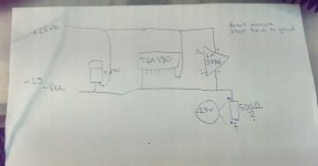
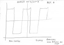
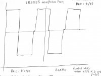
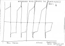
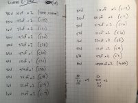
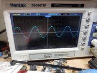
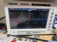
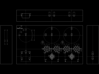
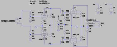
Cabbage! everything was going well, I would have also installed the protections and I could have fully tested my power supply, but something went wrong. Maybe the output filter? Perhaps the absence of Snubber on the output power diodes? It wasn't just a coincidence, because I fixed everything, and it happened again. I will post the schematic and some drawings of the waveforms that I saw on the oscilloscope before the failure, I have drawn them by hand, because it all happened yesterday, and I did not have the thought of taking pictures of the screen.


And of course, this is the videotest:
video

thanks to all,
Aids are appreciated!
Mario

Attachments

  • 20210405_221931.jpg
    20210405_221931.jpg
    418.7 KB · Views: 115
  • 20210405_221943.jpg
    20210405_221943.jpg
    438.8 KB · Views: 115
  • 20210405_221949.jpg
    20210405_221949.jpg
    391.7 KB · Views: 109
  • 20210405_221955.jpg
    20210405_221955.jpg
    458.2 KB · Views: 116
  • power transfer.jpeg
    power transfer.jpeg
    449.4 KB · Views: 112
  • pwm generator.jpeg
    pwm generator.jpeg
    348.4 KB · Views: 97
  • sg3525 signals.jpeg
    sg3525 signals.jpeg
    175.1 KB · Views: 88
  • ir2113s signals.jpeg
    ir2113s signals.jpeg
    209.3 KB · Views: 75
  • output signal before diodes.jpeg
    output signal before diodes.jpeg
    219.3 KB · Views: 71

hum resolved (hope it will be useful)

Hi,

The subwoofer I built (described in a previous post of mine) was starting to make an annoying hum.
The connection of the ground cable to the signal terminal was loose. Once the cable was fixed, the hum completely disappeared.
I forwarded this post because it was not easy to understand the problem as everything apparently worked.
I hope it will be useful.

Affordable(?) 3-way

I’ve been intrigued with the Philharmonitor BMR reviews, but had no desire to part with that sort of money, so I put together a pair of 3-ways using Hivi RT1.3 tweeters that Santa brought, and my Nomex 6.5” woofers that I have had for ages. I did splurge and bought a pair of Tectonic BMRs for midrange.
I salvaged and reconstructed cabinets from some TL enclosures, 8” wide and 12” deep.
I went totally active with the aid of a couple of Minidsp 2x4s. I already had one serving my LXminis.
I picked up a a Rotel 100w x2 amplifier for $60 on CL to go along with the NAD 7100 and 2155 that I used with my LXminis.
Crossed at 900hz and 3500hz LR4 and with a little EQ, they sound really good.
Very impressed with the mid driver, which I played full range for a while before final assembly. Female voice is to die for.
I’m going to replace the woofers with Dayton RS180p-4 since the Nomex drivers belong in my 2-way speakers. The Daytons are on sale at PE and may provide a little more low bass.
Stay safe and keep building.
Peter

Attachments

  • 2FAD8131-E86A-4D92-87F9-FDCE018119DB.jpg
    2FAD8131-E86A-4D92-87F9-FDCE018119DB.jpg
    364.1 KB · Views: 123

general and specific amplifier building questions

Transformer secondaries are 24Vac, recommended fuses 6.3A slow blow, 25A rectifier, 10.000 µF first cap, 140.000 µF second cap.

The toroid only 300 VA for mono, no inrush current limiter needed.

For raw testing I would like to keep it as simple as possible.

So the obvious question is, can I turn that on without blowing something ?

Does it make sense to put a 5W 0,33 ohms resistor between the caps ? and will it withstand power on surge ?

I could cut the 140.000 down to 120.000

Linear L-240 recap and...

Hello team, I've lurked on various audio repair forums a long long time. I'm finally ready, (I think) to get involved in a recap.

The subject at hand is a NZ made, likely in the 'heyday' for these vintage amps we know and love. Linear L-240 is the manufacturer and model.

The only 'data' I can find on this amplifier is here:
Happy birthday L240 • Heat • Public Address

Manufacturer may be mentioned here:
LINEAR Electronics Ltd Auckland New Zealand | Audiokarma Home Audio Stereo Discussion Forums

So the hopes of finding a datasheet are slim to impossible. Cool. Now I'm fairly new to soldering, but have access to a slick temperature regulated iron and I've been reading the how-to and tips for years. I think I'm ready to tackle a project. I also have a few friends who do this professionally, so I have the luxury of a few guides.

Now the amplifier worked momentarily, then began a feedback noise coming through. I suspect its the big capacitors in the power section, but as I'm learning, I would like to go through a full recap, to get a bit of practice in.

I've made a list of the capacitors. Are there any other things I should look at replacing? I've done some reading that suggests as long as capacitance remains the same, upping the voltage is okay. I've also read suggestions to keep the physical size of the capacitors the same, so that the legs pop in the circuit board without much mangling.

How would I go about measuring my current capacitors size to compare to the modern day offerings? Is there a physical sizing guide? Use a micrometer? Just a ruler for height / diameter? Are the physical sizes listed of the capacitors on mouser and such?

Any other challenges you wish to point out are helpful too.

I've included a couple photos of the project.

Dustin

Attachments

  • IMG_0412.jpg
    IMG_0412.jpg
    634.4 KB · Views: 327
  • IMG_0362.jpg
    IMG_0362.jpg
    1,019.5 KB · Views: 343

Nikko 220 mica insulators

Hello folks....I'm currently trying to refresh my Nikko 220 amp with a recap and I'm having a hard time finding replacement mica insulators for the power transistors. They must fit a 2SC2565 transistor as an example this being one of them. The old insulators measure 38mm long by 20mm wide with holes centred 25mm between. If I can't find new ones I'll have to clean and reuse the old ones but I'd rather not do that as one of the old ones is cracked. I've done a Google search and checked Mouser but can't pin it down to a correct one. Any help is appreciated.

Attachments

  • image.jpeg
    image.jpeg
    173.3 KB · Views: 132

European El Cheapo-ish build

In another thread (https://www.diyaudio.com/forums/tubes-valves/362926-stereo-tube-amp-build-advice.html) I asked about advice for a first tube stereo amplifier to build. Gladly a lot of people joined. After quite some switching back and forth and after extensive reading, searching and preparation I've just received my first goodies. Sourcing took a lot of time...
I chose some nice transformers from Amplimo; not El Cheapo. Not a dozen emails of every step in the delivery, but it was at my doorstep in no time. The packaging was top notch and they included a printed datasheet of the transformers. Perfect.

Attached you'll find a pdf with a lot of info I collected mostly from diyaudio threads and the original El Cheapo thread. It's not completed yet, just like the rest is not perfect.
I've also made my first PCB, which I'm planning to send to Aisler for manufacturing.
I've made the schematic in diylc as I've done before, but also in kicad once I thought a PCB would be nice. I also made a layout, not nearly as detailed as I would like, but I needed some hardware to make it more tangible.
Lastly, I made my first CAD drawing in QCAD. I've had good results with just printing (previously using inkscape) that to scale and stick it to the chassis for drilling. I've tried CAD programs before, but they were not my cup of tea. Somehow QCAD seems a lot more compatible with me.

I plan to keep you guys updated with the build progress.

In the mean time, any comments are appreciated. It's my first stereo amp build, so I can use the help.

Attachments

  • IMG_20210203_140603879.jpg
    IMG_20210203_140603879.jpg
    978.2 KB · Views: 835
  • IMG_20210203_140009311.jpg
    IMG_20210203_140009311.jpg
    982.8 KB · Views: 786
  • ElCheapo.png
    ElCheapo.png
    320.5 KB · Views: 756
  • pcb.png
    pcb.png
    52.4 KB · Views: 790
  • ElCheapoSchematic.png
    ElCheapoSchematic.png
    156.7 KB · Views: 2,007
  • ElCheapoLayoutPCB.jpg
    ElCheapoLayoutPCB.jpg
    585.1 KB · Views: 616
  • ElCheapo.pdf
    ElCheapo.pdf
    482.6 KB · Views: 514

ARTA and USB interface

Greetings all,

I need a new microphone, and doing my due diligence, I came across a reference, claiming that certain measurement software, namely ARTA, has problems with USB interface, e.g., when doing averaging.

So I am now considering a non-USB microphone. As I understand, they need a phantom power and perhaps an amplifier.

Are there any stringent requirements in regards to the phantom power, e.g., noise, or will one based on 78XX series regulators work? And what about the amplifier?

I am looking at the EMM-6. Any other recommendation?

Kindest regards,

M

Parallel Primary Inputs of Two Different Signal Transformers

I want to 'split' a balanced line signal so I was thinking of doing the following.

Balanced Line Output > 2 x 10k:10k Transformers > Separate Outputs

The balanced line output would be common for the primary inputs of the two transformers.

  1. Do you forsee any issues with this configuration?
  2. Will the input impedance of my system become 5kOhm? If so, what will be the output impedance now?

Optical or Coax Input to DAC

I recently ordered a couple of DACs and I've only ever used the internal ones in various devices.

If I use one on my computer, I'll obviously use the USB input. But what about other devices that have both an optical and coax output. Is there any reason to choose one over the other?

I'm sure there are technical differences, which I'm interested in, but I'm mainly concerned with any audible differences.

Does it just vary depending on the particular DAC, in which case you just try both and listen? Or is there some consensus 🙂rofl🙂 that applies to DACs in general?

How to get rid of hum in a 6AS7 Headphone Amp

I am in desperate need of some help. I would be very appreciative of anyone who can help me solve a problem with hum.

First, some background. I built the following headphone amp and it works perfectly, no hum.

Nobsound 6N5P+6N11 Vacuum Tube Headphone Amplifier Board DIY KIT Single end Class A Amp|Amplifier| - AliExpress

Next I got more ambitious and built the following headphone amp:

A Single-Ended OTL Amplifier for Dynamic Headphones. – HeadWize Memorial

This headphone is almost identical to the first. The amp part I built is exactly as in the Headwize link. The power supply for the filament is identical to the one from aliexpress. The high voltage power supply is a custom based on a bridge rectifier, followed by 47uf cap, followed by 50 ohm voltage dropping resistor, followed by 330uf cap, followed by 50 ohm voltage dropping resistor followed by 47uf cap. I have separate transformers for both filament and high voltage. The negative of both transformers is connected to circuit ground. The high voltage supply is on a separate board. The filament supply is on the same board, but on the other side of the board. the filament transformer is about 2 inches from the 6AS7.

The problem is that the Headwize amp has a severe hum. The hum is the same no matter what the volume is set to. The hum starts about 30 seconds after power on. If i turn the power off, the music continues to play for a few seconds without any hum. Also, I tried using 4 D batteries for the filament supply and the hum went away.

I have tried everything I can think of to solve this problem with no success, so as I said in the beginning I would greatly appreciate any help I can get. I used high end parts in the Headwize amp, hoping to have a better sound than the aliexpress one.

Pcm2902 sound good!easy use!

My friends told me he need USB DAC for computer record and KARAOKE with computer,I have use Roland UA-25ex many year,they have good parameter,
but I believe it so expensive.when my friend asked for me design USB DAC,I connect TI FAE,he suggest PCM2902 is excellent,cheap and good sound.So i works for it 2months,Test today ,sound excellent.I'll upload picture as attachment.
Friends on diyaudio have question why changing song there are POP sound,I found why!due to pcm2902 out signal need cap for dc isolation,you can try it once time,If you still have same problem,please mail me.

2type,one have 48v phantom power supply and combo XLR,other simple no phantom power only use XLR for banlance input and output.

Attachments

  • DSCF0607640480.JPG
    DSCF0607640480.JPG
    43.5 KB · Views: 385
  • DSCF0595640480.JPG
    DSCF0595640480.JPG
    65.7 KB · Views: 347
  • UA226404800.jpg
    UA226404800.jpg
    25.5 KB · Views: 356

Neurochrome DG300B Modified Build

I have had a set of boards for this amplifier for some time and I have finally started the build. I have some questions about the layout of the amp. Some background:

I am not an engineer (I am a nurse!) and this is my first project. Please do not assume that I know much.

The output valve will be the 6c4c which is a 7-pin version of a 2a3 and not the original 300B. I will be using the changes to the circuit detailed in Tom's build notes. I will also be inserting a Tribute AVC before the driver stage, making the amp a single input integrated. More on the AVC later.

Power transformer is a potted C-core from AEE. Output transformers are Tribute which I was very fortunate to get. Without testing my plan is for the Power transformer coils to be orientated front to back (so top to bottom on the diagram), OPTs left to right.

Top plate will be 450mm wide, 350mm deep. I have the aluminium already so not much scope for changing this. The Power transformer is 125mm square, the OPTs are 90mm square. The AVC is 50 x 50 x 100 and does not fit under the valves/PCB (amp becomes > 130mm tall which is too much for me)

Below is a very simple diagram with a proposed layout. The rounded square on the left is the Power transformer. Two squares top right and bottom right are the OPTs. Rhombus represents the 4 valves with 6c4c top and bottom, input valves (6n6p) left and right, each vertex representing a valve. These components are all on top of the aluminium top plate. The vertical rectangle between the OPTs is the AVC which is under the top plate. There is not quite enough room to fit the valves between the OPTs (OPTs are 90 x 90mm, distance between outer edges of 6c4c valves in Tom's boards are 164.3mm, the long axis of the rhombus). Call this Option 1.

Option 2 is to leave the Power transformer where it is but flip everything on the right side so the valves are now on the right edge and the OPTs and AVC are now moved approx. 80mm towards the centre. This has the advantage of getting the small signal valves further from the Power transformer but it is not as aesthetically pleasing.

These two options have the advantage of placing the inputs of the PCB closest to the rear panel, keeping wiring short.

Option 3 has OPTs back in the corners on the right side but would rotate the valves through 90 degrees so the valves can now sit between the OPTs. This also rotates the PCB under the top plate so the signal path from the input sockets to the PCB is now longer. Option 3 maximises the distance of both OPTs and valves from the Power transformer and could be the most aesthetically pleasing with the possibilty to have the 4 valves symetrically arranged between the two OPTs.

Any obvious preferences in these 3 options or is there something better I have not even considered?

Attachments

  • Layout ver.1.png
    Layout ver.1.png
    7.7 KB · Views: 204

Universal Remote Power Supply

Hey team,

Quick question for those who have enough in the mind palace -

I am itching to produce a universal dual mono supply in a chassis - to be configured with umbilical to compact heatsink-ed amp chassis....

So, let's say I wanted to build on PSU to power the following (theoretically): Aleph J, M2x, and F5T builds.... 2x600VA yielding 32V rails? seems perhaps a bit high for the Aleph, but can be biased down... is it too low for the F5T?

I'd love this so I can continue to build and swap around without incurring higher amp chassis costs (bulk) as well as Transformers, and the like.

FWIW, I rummaged around the forum a bit, but there is since there are differing directions on rail voltage, maybe someone can chime a solve-all answer in.

Thanks in advance!

300B LTspice model, SE with A-A feedback

I have a 300B and it is very dynamic and so on. But amplification is a bit high.
The trannie is LL2752.

So up came the idea of a internal feedback (anode-anode, not across the output transformer.

This is the basic idea:
Schermafbeelding 2019-03-19 om 15.46.58.jpg

The lower freq limit is lower than the -3db of the input (should be 25) but is modelled as 43 Hz. is fine with me. Lowering will give a little rise in the Va curve at the bottom end.
The high freq is quite high, at 80 kHz simulated.

Without feedback I get 8 Hz. And some 30 KHz. measured.
With different drivers I sometimes got 60 KHz measured,

any comments?

Attachments

Illustration of critical inductance

When using a choke input filter after a rectifier, some people prefer a multi-section filter, for example, L C L C: 5h-20u-5h-20U because it should reduce hum more than the same total L and C quantities used in a single section LC filter such as L C: 10H-40U.

Because the critical inductance depends on the minimum current to be drawn, it seems better for overall regulation when the minimum current is small, to use the singe section filter and put all the inductance before any capacitor filtering.

This would be for anode supply of class AB circuits having a low idling current, and in instrument-type regulated power supplies that have a wide range of load current. It should help to keep the no-load voltage from rising so much.

Parts on hand for this project are two 5H inductors and two 20uF capacitors. How to arrange them?

The chart shows data from PSUD for a proposed high voltage supply. The program was run using constant current loads from almost zero to 2A.

It shows that a single 10H choke followed by a 40uF capacitor gives better voltage regulation at lower currents (0.25A) than a two section filter mad of two 5H chokes and tow 20uF capacitors.

I hope this makes sense. I wish I had a 20H choke or higher that would take the current.

Attachments

  • lcrit.png
    lcrit.png
    18.5 KB · Views: 417

isolation/support for HEAVY Altec vot

Hello,
I am looking for some diy solution or non audiophile price ( so general purpose) so isolate my Altec Vot cabinets they are above 100 kilogram( 220 pounds) . I have no way to check the weight. So it could be a bit higher. Maybe i will add a bag of sand on top lol but i need something to give a better isolation than the rubber wheels.
Something like a ''pile '' of 4 square inch of 3.5 mm 1/8 inch thickness cork ''sheets '' like the ones on my wall or get some thicker cork panels normally used for temperature/sound isolation? I can make a sandwich of cork and lead sheets.
Any ideas are welcome.
Greetings,Eduard

Attachments

  • 20201125_160047kl.jpg
    20201125_160047kl.jpg
    464.1 KB · Views: 182

Replace ALPS Pot on Rega Mira

Hey all,
Did some digging online and I haven't come across a thread on this that I could find.


Anyone ever replace the volume/selector switch ALPS Pot on a Rega Mira series integrated? I've seen the scratchy intermittent switch is very common, but I've never seen an actual replacement solution.


Does anyone know if this would work?

ALPS 50KAX2 50K Ohm Audio Taper Stereo Potentiometer 6mm Shaft


Thanks for any thoughts or experience!

Attachments

  • Screen Shot 2020-03-03 at 10.04.08 PM.png
    Screen Shot 2020-03-03 at 10.04.08 PM.png
    130.5 KB · Views: 151
  • Screen Shot 2020-03-03 at 10.04.20 PM.png
    Screen Shot 2020-03-03 at 10.04.20 PM.png
    194.3 KB · Views: 148
  • Screen Shot 2020-03-03 at 10.03.22 PM.png
    Screen Shot 2020-03-03 at 10.03.22 PM.png
    110.3 KB · Views: 132

MOSFET for capacitor multiplier

I plan to use the attached circuit from Menno van der veen's article on AudioXpress in the power supply of a single ended EL84 amp. The voltage after the rectifiers will be 320V. The current is around 100 mA max.

I found this MOSFET IPAN70R450P7S from Mouser. The datasheet link is here https://www.infineon.com/dgdl/Infin...N.pdf?fileId=5546d4625f2e26bc015f499adf55405f.

What are the specific requirements for the MOSFET in this circuit? Is there any concerns on using IPAN70R450P7S? Since this part has built-in protection diodes, do I still need Z3? What will be the voltage drop across the circuit?

Attachments

  • Capture.JPG
    Capture.JPG
    78.6 KB · Views: 1,722

Hypex SMPS400A180

Hi. I have one monitor speaker that have 2 bridged UcD180 modules on 8ohm load for bass and 1 of same module on tweeter duty with this power supply.After 2 years of working ,last week on power up it wont work.As an electrical engineer myself i found that on power up 2 transistor of the supply board poppd up.The 2 in question are T7 and T14. The first is an smd part and i cant read it what it was,with some intuition and a little schematic i draw i think is an high voltage pnp part.The T14 is an npn KSP44.I already emailed hypex to ask what part number it is so i can change it myself and no answer for now.I must mention that the fast 5A fuse is working,the bridge rectifier too and the caps are good.Is only missing the low voltage startup part.
I ask is anyone have a module at hand if can make an macro picture of the tiny transistor to see the number printed.
Thank you in advance.
Daniel

PP amp driven with balanced input source

As a I am wrapping my current project (RH807 SE amp) I am thinking of the next project to build on this experience.

My DAC has 6.4V rms balanced outputs. So I was thinking of using this to design a PP amp without a phase splitter. Volume control would be done using a stereo stepped attenuator for channel. Would the topology a good starting point? Ignore the component values as I have not optimized the o.p. yet.

Attachments

  • pp_diff_input.png
    pp_diff_input.png
    46.8 KB · Views: 289

ECL82 Class-A amp - No sound

I built my first tube amplifier based on this schematic:
Single Tube amplifier
The amp powers on and I hear a subtly audible hum from the speaker that I would atribute to the power supply and heater wires.
I''m not getting any audi out, just a slight "hissing" sound.

I've modified the schematic below - I currently have the audio input from the pot with a 220k resistor in series and no ground. I'm thinking this is the issue, but not sure.

5W_ECL82_SE_amplifier | Zack Fedor | Flickr

Using a Triad R-23B power transformer
5k 8ohm output transformer from China (nice one though)
8 ohm speaker
USSR 6Mb8 tube, tested strong
1N4001 diodes on the rectifier
All componenets either new or in perfect working condition

I would appreciate any input 🙂

Communications Rectifier hot swap NPR24/48 information

Hello,
I have many NPR24 hot swappable rectifiers which were used in RF communication centres. These plug into a magazine and run in parallel to provide large currents for comms gear such as paging and LTE Transmitters.
Not Audio related however, these Switching power supplies are exceptionally well built and utilise ZVS topology as well as Power factor correction to minimise interference. The control uses a Atmel Mega32L and communicates using RS-485 modbus link (I think) communicates between the SM60 supervisory controller.

The NPR series where made back in 2007 by Powerware now bought out by Eaton.
I’ve contracted Eaton a few times regarding technical info, schematic and the modbus register map and as expected, got blown off. Can’t give information as its propitiatory line. Shame!
I feel there’s life left in these old girls and I’m finding plenty of used ones coming up on the web for not much at all. I’d like to save them from land fill or going to green waste and reverse engineering how to talk to them.

Question is, is there anyone with information about these such as register map for the modbus and schematic.

Somebody out there probably repairs them in early days.
Please PM if you can help out. Pictures attached

Cheers

Attachments

  • 54FBCCF6-22B8-4871-BF02-697AC64C4A26.jpeg
    54FBCCF6-22B8-4871-BF02-697AC64C4A26.jpeg
    160.7 KB · Views: 112
  • CAD1AEDA-00F1-4CA7-A547-7818E85D06D4.jpeg
    CAD1AEDA-00F1-4CA7-A547-7818E85D06D4.jpeg
    201.9 KB · Views: 107
  • 1AD89690-F507-4B5B-BF93-68F553B67813.jpeg
    1AD89690-F507-4B5B-BF93-68F553B67813.jpeg
    182.6 KB · Views: 105

FS pair of paper mache 160hz tractrix round horn

DIY paper mache round horn. Mouth diameter is 26 in. Throat is 1.5 in. Mounting flanges for JBL 2450 series compression driver included. Pin point stereo imaging even if put in corners. $100 for the pair. Local pick up only in Oceanside CA 92057

Attachments

  • 20210302_145405.jpg
    20210302_145405.jpg
    494.2 KB · Views: 408
  • 20210302_145434.jpg
    20210302_145434.jpg
    376.9 KB · Views: 373
  • 20210302_145353.jpg
    20210302_145353.jpg
    548.9 KB · Views: 377
  • 20210302_145247.jpg
    20210302_145247.jpg
    450.2 KB · Views: 356
  • 20210302_145458.jpg
    20210302_145458.jpg
    420.3 KB · Views: 373
  • 20210302_151923.jpg
    20210302_151923.jpg
    407.1 KB · Views: 224
Projects by fanatics, for fanatics
Get answers and advice for everyone wanting to learn the art of audio.
Join the Community
507,912
Members
7,893,401
Messages

Filter

Forum Statistics

Threads
406,476
Messages
7,893,401
Members
507,912
Latest member
Gopisai