In another thread (https://www.diyaudio.com/forums/tubes-valves/362926-stereo-tube-amp-build-advice.html) I asked about advice for a first tube stereo amplifier to build. Gladly a lot of people joined. After quite some switching back and forth and after extensive reading, searching and preparation I've just received my first goodies. Sourcing took a lot of time...
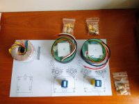
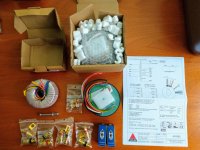
I chose some nice transformers from Amplimo; not El Cheapo. Not a dozen emails of every step in the delivery, but it was at my doorstep in no time. The packaging was top notch and they included a printed datasheet of the transformers. Perfect.
Attached you'll find a pdf with a lot of info I collected mostly from diyaudio threads and the original El Cheapo thread. It's not completed yet, just like the rest is not perfect.
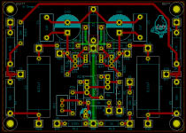
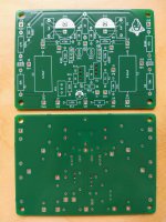
I've also made my first PCB, which I'm planning to send to Aisler for manufacturing.
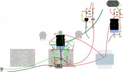
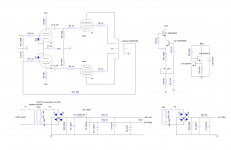
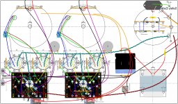
I've made the schematic in diylc as I've done before, but also in kicad once I thought a PCB would be nice. I also made a layout, not nearly as detailed as I would like, but I needed some hardware to make it more tangible.
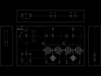
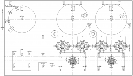
Lastly, I made my first CAD drawing in QCAD. I've had good results with just printing (previously using inkscape) that to scale and stick it to the chassis for drilling. I've tried CAD programs before, but they were not my cup of tea. Somehow QCAD seems a lot more compatible with me.
I plan to keep you guys updated with the build progress.
In the mean time, any comments are appreciated. It's my first stereo amp build, so I can use the help.
I chose some nice transformers from Amplimo; not El Cheapo. Not a dozen emails of every step in the delivery, but it was at my doorstep in no time. The packaging was top notch and they included a printed datasheet of the transformers. Perfect.
Attached you'll find a pdf with a lot of info I collected mostly from diyaudio threads and the original El Cheapo thread. It's not completed yet, just like the rest is not perfect.
I've also made my first PCB, which I'm planning to send to Aisler for manufacturing.
I've made the schematic in diylc as I've done before, but also in kicad once I thought a PCB would be nice. I also made a layout, not nearly as detailed as I would like, but I needed some hardware to make it more tangible.
Lastly, I made my first CAD drawing in QCAD. I've had good results with just printing (previously using inkscape) that to scale and stick it to the chassis for drilling. I've tried CAD programs before, but they were not my cup of tea. Somehow QCAD seems a lot more compatible with me.
I plan to keep you guys updated with the build progress.
In the mean time, any comments are appreciated. It's my first stereo amp build, so I can use the help.
Attachments
Attached you'll find a pdf with a lot of info I collected mostly from diyaudio threads and the original El Cheapo thread. It's not completed yet, just like the rest is not perfect.
Nice, this collected info. Thanks.
ignore the following - just seen your CCS is in the cathode.
my experience with the dn2540 is that they are sensitive things near 400v, which you may get close to with if primary is a bit high. I also prefer the sound the IXTP08N100D2 and they are good to 1000v. I have have lost several dn2540s at switch on with a similar target b+
my experience with the dn2540 is that they are sensitive things near 400v, which you may get close to with if primary is a bit high. I also prefer the sound the IXTP08N100D2 and they are good to 1000v. I have have lost several dn2540s at switch on with a similar target b+
adamus,
Good point, for whenever a dn2540 is used in the plate circuit of a tube amplifier.
I find similar problems when the designer uses a 400V RC coupling cap, when the B+ is choke loaded 315V.
The explanation is in 1. below.
1. A different amplifier circuit:
A dn2540 in the plate circuit of a tube that RC couples to the next stage can be a problem.
Suppose the Loaded B+ to that dn2540 is 315V from a choke input B+ supply. That works good, when the B+ is at 315V.
But, at turn on, before the tubes warm up, the unloaded voltage of that B+ is:
315V/0.9 x 1.414 = 495V B+.
495V B+ to the drain of the dn2540, the source of the dn2540 connects to the capacitor of the RC coupling circuit, the other end of the capacitor connects to the grid resistor, Rg, and Rg connects to ground.
* That capacitor also connects to the grid of the following tube.
* Some amplifiers Output tubes, have a grid protection diode from that grid to the cathode of that tube.
The cathode is generally connected to a medium or low resistance to ground.
During that transient, the capacitor starts with 0 volts across it (it acts just like a dead short), and it starts charging through the next stage Rg, * and through the grid protection diode if it is present.
Then . . . Bang! a dead dn2540.
And, similarly, if the coupling cap is only rated for 400V, the turn on B+ of 495 Volts is a problem for that cap.
I use 600V or 630V rated caps there.
2. EL Cheapo amplifier:
A 400V rated dn2540 that is in the cathode circuit of the phase inverter would not get 400V at turn-on.
The filament to cathode of that inverter tube would short first.
And, if there were 400V on the cathode, the cathode would arc to the grid as well.
Using the dn2540 in the El Cheapo, there will be no 400V transient there.
It should work well in that application.
3. It is true. I have never used a dn2540.
But it seems to me that the El Cheapo designs have been built many many times, and I do not remember of a report of a dead dn2540 that was caused by transient there on the cathode that exceeded 400V (that is either caused by bad input tube shorts, or it would cause a bad input tubes, because of the short/arcs to the grid, filament, or both).
Last edited:
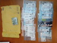
Next shipment has arrived. The pcb's and some part from Aisler. Nice service, I would buy from them again.
Nicely packaged. Some components are for the pcb. You can couple components to R../C.. on the pcb, but you can also add other components which allow you to order stuff from mouser and digikey as a private person.
Pcb looks very nice (to a noob...). Only thing that looks weird are the pads of Q1&2. It seems that the 'model' I used in Kicad was has no solder mask. Any tips how to remove that?
Still need to source some components I tried to buy from RS Online, but they don't sell to private persons.
Attachments
Still need to source some components I tried to buy from RS Online, but they don't sell to private persons.
Farnell sells to private persons.
But they only "deliver" with UPSFarnell sells to private persons.
Not much progress lately... Still waiting for parts, also because of a grounding scheme discussion in another thread.
So... I tried the headphone trick on the toroidal transformer. I've used the trick before as can be seen here: Quick demo of influence of output transformer orientation on hum - YouTube
The toriods are quiet, dead quiet. I doubted my setup, but moving my headphone-hookup wires closer to the PT, I can here a slight buzz so my setup works. There is a mechanical vibration of the PT amplified by the desk. I hope the rubber pads will solve that in the real amp.
Probably. But is it a drop in replacement? Pcb's are ready...
I have 10M45s for you if you want them, same pinout same function.
PS: im quite fond of TME.EU they sell to individuals no problem, just 8.75 shipping.
The 10M45S is kind of like a beefier DN2540 anyway, the only reason its 50 cents more is because the device is quite accurate.
A good replacement for the MJE340 is the TTA006B by Toshiba, much higher Hfe and FT much lower miller capacitance.
I wanted to ask? is that PCB drawn in Kicad?
A good replacement for the MJE340 is the TTA006B by Toshiba, much higher Hfe and FT much lower miller capacitance.
I wanted to ask? is that PCB drawn in Kicad?
")
Most (hopefully all...) parts have arrived. I _think_ I have the layout and the 'drill plan' as ready as can be. I measured a lot of components and added bounding boxes. This weekend I plan to make a prototype from a thin piece of woodlike material.
Anything I completely overlooked?
ps. The rectification parts location still a bit unsure.
Anything I completely overlooked?
ps. The rectification parts location still a bit unsure.
Attachments
- Status
- This old topic is closed. If you want to reopen this topic, contact a moderator using the "Report Post" button.
- Home
- Amplifiers
- Tubes / Valves
- European El Cheapo-ish build