I have had a set of boards for this amplifier for some time and I have finally started the build. I have some questions about the layout of the amp. Some background:
I am not an engineer (I am a nurse!) and this is my first project. Please do not assume that I know much.
The output valve will be the 6c4c which is a 7-pin version of a 2a3 and not the original 300B. I will be using the changes to the circuit detailed in Tom's build notes. I will also be inserting a Tribute AVC before the driver stage, making the amp a single input integrated. More on the AVC later.
Power transformer is a potted C-core from AEE. Output transformers are Tribute which I was very fortunate to get. Without testing my plan is for the Power transformer coils to be orientated front to back (so top to bottom on the diagram), OPTs left to right.
Top plate will be 450mm wide, 350mm deep. I have the aluminium already so not much scope for changing this. The Power transformer is 125mm square, the OPTs are 90mm square. The AVC is 50 x 50 x 100 and does not fit under the valves/PCB (amp becomes > 130mm tall which is too much for me)
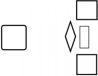
Below is a very simple diagram with a proposed layout. The rounded square on the left is the Power transformer. Two squares top right and bottom right are the OPTs. Rhombus represents the 4 valves with 6c4c top and bottom, input valves (6n6p) left and right, each vertex representing a valve. These components are all on top of the aluminium top plate. The vertical rectangle between the OPTs is the AVC which is under the top plate. There is not quite enough room to fit the valves between the OPTs (OPTs are 90 x 90mm, distance between outer edges of 6c4c valves in Tom's boards are 164.3mm, the long axis of the rhombus). Call this Option 1.
Option 2 is to leave the Power transformer where it is but flip everything on the right side so the valves are now on the right edge and the OPTs and AVC are now moved approx. 80mm towards the centre. This has the advantage of getting the small signal valves further from the Power transformer but it is not as aesthetically pleasing.
These two options have the advantage of placing the inputs of the PCB closest to the rear panel, keeping wiring short.
Option 3 has OPTs back in the corners on the right side but would rotate the valves through 90 degrees so the valves can now sit between the OPTs. This also rotates the PCB under the top plate so the signal path from the input sockets to the PCB is now longer. Option 3 maximises the distance of both OPTs and valves from the Power transformer and could be the most aesthetically pleasing with the possibilty to have the 4 valves symetrically arranged between the two OPTs.
Any obvious preferences in these 3 options or is there something better I have not even considered?
I am not an engineer (I am a nurse!) and this is my first project. Please do not assume that I know much.
The output valve will be the 6c4c which is a 7-pin version of a 2a3 and not the original 300B. I will be using the changes to the circuit detailed in Tom's build notes. I will also be inserting a Tribute AVC before the driver stage, making the amp a single input integrated. More on the AVC later.
Power transformer is a potted C-core from AEE. Output transformers are Tribute which I was very fortunate to get. Without testing my plan is for the Power transformer coils to be orientated front to back (so top to bottom on the diagram), OPTs left to right.
Top plate will be 450mm wide, 350mm deep. I have the aluminium already so not much scope for changing this. The Power transformer is 125mm square, the OPTs are 90mm square. The AVC is 50 x 50 x 100 and does not fit under the valves/PCB (amp becomes > 130mm tall which is too much for me)
Below is a very simple diagram with a proposed layout. The rounded square on the left is the Power transformer. Two squares top right and bottom right are the OPTs. Rhombus represents the 4 valves with 6c4c top and bottom, input valves (6n6p) left and right, each vertex representing a valve. These components are all on top of the aluminium top plate. The vertical rectangle between the OPTs is the AVC which is under the top plate. There is not quite enough room to fit the valves between the OPTs (OPTs are 90 x 90mm, distance between outer edges of 6c4c valves in Tom's boards are 164.3mm, the long axis of the rhombus). Call this Option 1.
Option 2 is to leave the Power transformer where it is but flip everything on the right side so the valves are now on the right edge and the OPTs and AVC are now moved approx. 80mm towards the centre. This has the advantage of getting the small signal valves further from the Power transformer but it is not as aesthetically pleasing.
These two options have the advantage of placing the inputs of the PCB closest to the rear panel, keeping wiring short.
Option 3 has OPTs back in the corners on the right side but would rotate the valves through 90 degrees so the valves can now sit between the OPTs. This also rotates the PCB under the top plate so the signal path from the input sockets to the PCB is now longer. Option 3 maximises the distance of both OPTs and valves from the Power transformer and could be the most aesthetically pleasing with the possibilty to have the 4 valves symetrically arranged between the two OPTs.
Any obvious preferences in these 3 options or is there something better I have not even considered?
Attachments
Just a small consideration. I've been having very good results with DC Link capacitors, available from RS in the UK. They sound better than anything I've tried as a cathode bypass cap on my 300b output, and it would be the same with 6C4C in self bias. They would also be brilliant in the power supply specially as the last cap before the outputs and a cap after a dropper resistor for the input stage. Or even right through. They're an unusual box shape so would have to be planned for. I think it would be worth it - very clear and detailed and a step up sonically. I attach them with stackable nylon M3 hexagonal spacers I buy from Rapid. I use those everywhere, with solder tags on top.
Affix Nylon Hexagonal Male - Female Spacers 12.7mm - Pack Of 100 | Rapid Online
PJP C3 Solder Tags Plated M3 Pack Of 100 | Rapid Online
Affix Nylon Hexagonal Male - Female Spacers 12.7mm - Pack Of 100 | Rapid Online
PJP C3 Solder Tags Plated M3 Pack Of 100 | Rapid Online