I have played around with similar simple circuits in the past for fun with numerous BJT Darlington Pairs as single package or discrete. Usually obtained around .0006 to .001%
1Watt THD1 using the classic 5534 as the driver. Typical expected 18 to 27 watts with op amps that you might tippy toe into the 22 volt area. ( Yeah Whatever more like 15 to 22 watts) to be safe.
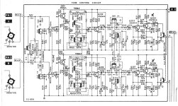
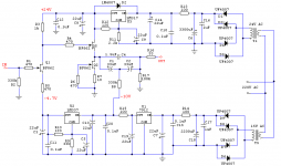
A circuit design example was requested. So I made sure I was not blowing smoke up my own butt. Put together a more final circuit with hopefully real world stability margin.
Then run it up close to crest power and see what THD20 ( 20 kHz) was. Then post another sim amp that people love so much. Somebody might do a PCB ( probably not) and remind me diode thermal tracking makes everyone yell at the clouds. Until someone just has fun and is actually creative enough to build one. Woo Hoo
I like using diodes sometimes, because its fun and also easier with op amp drivers to use Boot Strap current source for the hardest swing you can get. Maybe live the Fantasy of getting 25 to 27 watts into a 4 ohm load. It actually does swing rather well driving a Darlington pair. The simple bias adjustment circuit will basically get you going dead centered at 50%. If you want to run 85 to 100ma for high frequency numbers about 55 to 65% will do it.
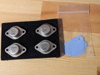
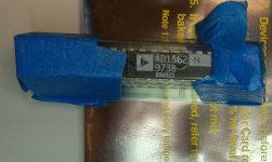
Yep T0-220 package for power transistor Using 80 volt 80 watt, 50 MHz fT with around max 1 amp current expected hfe should Hold 80 to 100 and yes minimum is rated 35 to 40 like a zillion other T0-220. D44VH10(NPN),D45VH10 (PNP) manufactured currently by On-Semi
------------------------------------------------------------------------------------------------------------------------------------------------------------------------------------------------------
Bandwidth 1 Hz to 514 kHz stability phase margin 50° ( thumbnail click to enlarge)

Clipping Behavior 4 ohm load ( thumbnail click to enlarge)

No Overshoot / Gain peaking 20 kHz 4 ohm load ( thumbnail click to enlarge)

THD1 ( 1 kHz) 2.83V output 1 Watt

THD20 ( 20 kHz) 2.83V rms output 1 Watt

THD1 ( 1kHz) and THD20 ( 20kHz) with 300mV input and 900mV input 8 ohm and 4 ohm
8 ohm load
============================
300mV input 8 ohm Load 1.2 Watts output
============================
THD1 .0004 %
THD20 .003 %
============================
900mV input 8 ohm Load 11.2 Watts output
============================
THD1 .003 %
THD20 .007 %
-------------------------------------------------
4 ohm load
============================
300mV input 4 ohm Load 2.4 Watts output
============================
THD1 .0004 %
THD20 .006 %
=============================
900mV input 4 ohm Load 22.5 Watts output
=============================
THD1 .004 %
THD20 .01 %
-------------------------------------------------
Slew Rate Measured 10 kHz 10 Volt Peak to Peak , 5 Volt Peak Delta X Delta Y 10% 90% 551 Nano Seconds
= 14.5V/us Slew Rate