Hi,
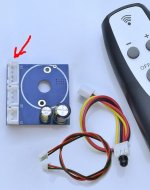
I have the ALPS27 Motor Potentiometer that I bought some time ago. I got it with a circuit for the remote conrol. But Ihave been looking all over to get a circuit diagram so that I can determine exactly what the J3 connector is used for. But I can not find anything. Any help with this is greatly appreciated.
I have the ALPS27 Motor Potentiometer that I bought some time ago. I got it with a circuit for the remote conrol. But Ihave been looking all over to get a circuit diagram so that I can determine exactly what the J3 connector is used for. But I can not find anything. Any help with this is greatly appreciated.
Attachments
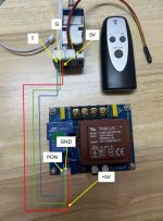
It's for powering the board with 5VDC instead of using the AC header. Only the 5V and G pins are used (should be marked on the PCB). The R and T pins are not used for anything.

Hi,Hi,
I have the ALPS27 Motor Potentiometer that I bought some time ago. I got it with a circuit for the remote conrol. But Ihave been looking all over to get a circuit diagram so that I can determine exactly what the J3 connector is used for. But I can not find anything. Any help with this is greatly appreciated.
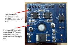
I know its a bit late, but this is what I discovered. the "T" pin is a trigger pin to turn ON/OFF a dedicated power supply relay.
for your motor to enable this "T" pin feature, you need to short "S2". After all is done, the ALPS motor will only work when you press ON from the IR remote.
BTW, you do not need to plug anything to the AC input on the ALPS motor board for this setup, the dedicated power supply will provide the voltage.
Hope this help.
-B.Keat