
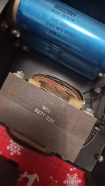
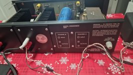
The Crescendo went through many changes over the years. I think the first was a CFP design (I'm working on one now), and then it went to a CE design, followed by a couple of MOSFET versions. I am somewhat confident you have a BJT model, either CFP or CE, but you would want to verify. The photo - is that your amp? Can you open the case and photograph the right channel module showing the board and another the output transistors, please?
These amps are getting old now, and depending on how yours was maintained, the output transistors may each have drifted a lot since new. The one I'm working on had all original MJ15003/4 that had drifted down to 60, 49, 41, and 11 hFE so I replaced them.
These amps are getting old now, and depending on how yours was maintained, the output transistors may each have drifted a lot since new. The one I'm working on had all original MJ15003/4 that had drifted down to 60, 49, 41, and 11 hFE so I replaced them.
Yes, it's mine. Now it is in the hands of a friend who could help me adjust the bias and therefore I have no way to take further photos: I will reply as soon as I have more information. TKSThe Crescendo went through many changes over the years. I think the first was a CFP design (I'm working on one now), and then it went to a CE design, followed by a couple of MOSFET versions. I am somewhat confident you have a BJT model, either CFP or CE, but you would want to verify. The photo - is that your amp? Can you open the case and photograph the right channel module showing the board and another the output transistors, please?
These amps are getting old now, and depending on how yours was maintained, the output transistors may each have drifted a lot since new. The one I'm working on had all original MJ15003/4 that had drifted down to 60, 49, 41, and 11 hFE so I replaced them.
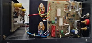
I can't really see the output transistors, so don't know if you have the BJT model or not.
Your friend hasn't helped you with this yet?
Is it functioning properly, other than needing bias adjustment? What is the bias now?
Your friend hasn't helped you with this yet?
Is it functioning properly, other than needing bias adjustment? What is the bias now?

Google translates your comment as:
"One of the two channels distorts, but I'm not even sure that the other channel is well polarized"
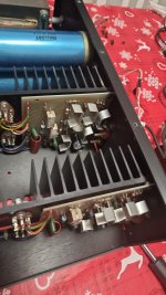
This is the same version of the amp I'm working on now. This is a Complimentary Feedback Pair (CFP) design. There is no available schematic I'm aware of for this amp, but you can get some useful information from the only schematic on the internet for the later version, a Common Emitter design using MJ15022/3 outputs and MJE15030/1 drivers. There are a lot of other differences as well, and I see some of the resistor values on your boards differ from the ones I'm working on.
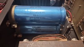
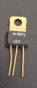
These are now quite old, and if you have one channel distorting, it may have more than one problem. I recommend you take it to a repair tech, rather than fiddle with bias, but you could of course have your friend record the bias as a baseline. It has new high quality electrolytic caps and a new Zobel resistor, which is good. It also looks like some resistors have been replaced. I've had these boards apart several times, as each test has shown other bad components I didn't replace at first (e.g. bad output transistors, broken legs on MPSU07, leaky 1N4003 diode, and flaky 0.1uF Mylar caps, which didn't show as bad on cheap testers, but did on my expensive LCR meter. Even one trimmer tested way under 10k, so I'm awaiting an order for a new one and a couple of other parts so I can finish repairing the amp.
Distortion could be the result of a mismatched input pair, incorrect voltages throughout the input and VAS section, bad film caps, bad diodes, or failing/low hFE output transistors. Those components need to be tested and the channel properly diagnosed, particularly if bias as measured across the collector resistors (they are not emitter resistors) indicates very high or very low bias.
Since these are BJTs, I think it should be safe to adjust bias to between 25-50 mA per device as measured across one collector resistor. For each 0.22 resistor, you might want to shoot for between 5-10mV. If you measure the collector resistors individually, you might well find a large spread in bias current, as the original output transistors are very possibly way out of specification now.
Most of the active parts on the boards are NLA, so be careful working on them. The amp is sensitive to any imbalances and parts substitutions and will oscillate easily if you aren't careful. Make sure to short the inputs and have an 8 Ohm load on the speaker outputs, and make sure the heat sink is grounded to the enclosure by the screws or a short, stout jumper (don't just rely on the black ground wire from the PS).
"One of the two channels distorts, but I'm not even sure that the other channel is well polarized"
This is the same version of the amp I'm working on now. This is a Complimentary Feedback Pair (CFP) design. There is no available schematic I'm aware of for this amp, but you can get some useful information from the only schematic on the internet for the later version, a Common Emitter design using MJ15022/3 outputs and MJE15030/1 drivers. There are a lot of other differences as well, and I see some of the resistor values on your boards differ from the ones I'm working on.
These are now quite old, and if you have one channel distorting, it may have more than one problem. I recommend you take it to a repair tech, rather than fiddle with bias, but you could of course have your friend record the bias as a baseline. It has new high quality electrolytic caps and a new Zobel resistor, which is good. It also looks like some resistors have been replaced. I've had these boards apart several times, as each test has shown other bad components I didn't replace at first (e.g. bad output transistors, broken legs on MPSU07, leaky 1N4003 diode, and flaky 0.1uF Mylar caps, which didn't show as bad on cheap testers, but did on my expensive LCR meter. Even one trimmer tested way under 10k, so I'm awaiting an order for a new one and a couple of other parts so I can finish repairing the amp.
Distortion could be the result of a mismatched input pair, incorrect voltages throughout the input and VAS section, bad film caps, bad diodes, or failing/low hFE output transistors. Those components need to be tested and the channel properly diagnosed, particularly if bias as measured across the collector resistors (they are not emitter resistors) indicates very high or very low bias.
Since these are BJTs, I think it should be safe to adjust bias to between 25-50 mA per device as measured across one collector resistor. For each 0.22 resistor, you might want to shoot for between 5-10mV. If you measure the collector resistors individually, you might well find a large spread in bias current, as the original output transistors are very possibly way out of specification now.
Most of the active parts on the boards are NLA, so be careful working on them. The amp is sensitive to any imbalances and parts substitutions and will oscillate easily if you aren't careful. Make sure to short the inputs and have an 8 Ohm load on the speaker outputs, and make sure the heat sink is grounded to the enclosure by the screws or a short, stout jumper (don't just rely on the black ground wire from the PS).
Yes, those are way too delicate, especially with those big heat sinks! The amps I've been working on have had 3 with broken legs. Unfortunately, those are no longer available.

Excellent!
I presume you bought the CEN parts? I have used some before but the hFE was different from original.
Glad you got it back in service!
I presume you bought the CEN parts? I have used some before but the hFE was different from original.
Glad you got it back in service!
@aria - I've just restored a rare Audire integrated amp - the Adagio. The amp portion is very much a Crescendo, but with BJT drivers and MOSFET outputs - IRF130/IRF9130. Julius made many variants of his earlier amps, offering BJT or MOSFET, and there are many component changes as a result. The Crescendo I've been working that is identical to yours has been giving me trouble with one channel, but I'm hoping my latest discovery solves the problem. I'm mentioning it to you so your friend can check your amp as well...
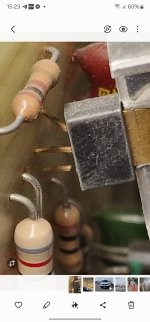
One of the 0.22R collector resistors (the big white ceramic ones) on one board failed almost completely open, with no outward signs of damage. The other is OK, but measures a bit high. It can be difficult to accurately measure very small resistances, but with a good meter, with nulled leads, you should be able to verify they still measure properly.
I've never heard the smaller Audire amps before repairing this Adagio, though my brother had the Otez and it was incredible. This sounds amazing for a 75WPC CFP amp - very detailed mid- and hi-range, and very respectable bass. I hope yours is back up to its proper performance - happy listening! Buon ascolto!
- Home
- Amplifiers
- Solid State
- Audire Crescendo bias adjustment