I have played around with similar simple circuits in the past for fun with numerous BJT Darlington Pairs as single package or discrete. Usually obtained around .0006 to .001%
1Watt THD1 using the classic 5534 as the driver. Typical expected 18 to 27 watts with op amps that you might tippy toe into the 22 volt area. ( Yeah Whatever more like 15 to 22 watts) to be safe.
A circuit design example was requested. So I made sure I was not blowing smoke up my own butt. Put together a more final circuit with hopefully real world stability margin.
Then run it up close to crest power and see what THD20 ( 20 kHz) was. Then post another sim amp that people love so much. Somebody might do a PCB ( probably not) and remind me diode thermal tracking makes everyone yell at the clouds. Until someone just has fun and is actually creative enough to build one. Woo Hoo
I like using diodes sometimes, because its fun and also easier with op amp drivers to use Boot Strap current source for the hardest swing you can get. Maybe live the Fantasy of getting 25 to 27 watts into a 4 ohm load. It actually does swing rather well driving a Darlington pair. The simple bias adjustment circuit will basically get you going dead centered at 50%. If you want to run 85 to 100ma for high frequency numbers about 55 to 65% will do it.
Yep T0-220 package for power transistor Using 80 volt 80 watt, 50 MHz fT with around max 1 amp current expected hfe should Hold 80 to 100 and yes minimum is rated 35 to 40 like a zillion other T0-220. D44VH10(NPN),D45VH10 (PNP) manufactured currently by On-Semi

------------------------------------------------------------------------------------------------------------------------------------------------------------------------------------------------------
Bandwidth 1 Hz to 514 kHz stability phase margin 50° ( thumbnail click to enlarge)

Clipping Behavior 4 ohm load ( thumbnail click to enlarge)

No Overshoot / Gain peaking 20 kHz 4 ohm load ( thumbnail click to enlarge)

THD1 ( 1 kHz) 2.83V output 1 Watt

THD20 ( 20 kHz) 2.83V rms output 1 Watt

THD1 ( 1kHz) and THD20 ( 20kHz) with 300mV input and 900mV input 8 ohm and 4 ohm
8 ohm load
============================
300mV input 8 ohm Load 1.2 Watts output
============================
THD1 .0004 %
THD20 .003 %
============================
900mV input 8 ohm Load 11.2 Watts output
============================
THD1 .003 %
THD20 .007 %
-------------------------------------------------
4 ohm load
============================
300mV input 4 ohm Load 2.4 Watts output
============================
THD1 .0004 %
THD20 .006 %
=============================
900mV input 4 ohm Load 22.5 Watts output
=============================
THD1 .004 %
THD20 .01 %
-------------------------------------------------
Slew Rate Measured 10 kHz 10 Volt Peak to Peak , 5 Volt Peak Delta X Delta Y 10% 90% 551 Nano Seconds
= 14.5V/us Slew Rate

1Watt THD1 using the classic 5534 as the driver. Typical expected 18 to 27 watts with op amps that you might tippy toe into the 22 volt area. ( Yeah Whatever more like 15 to 22 watts) to be safe.
A circuit design example was requested. So I made sure I was not blowing smoke up my own butt. Put together a more final circuit with hopefully real world stability margin.
Then run it up close to crest power and see what THD20 ( 20 kHz) was. Then post another sim amp that people love so much. Somebody might do a PCB ( probably not) and remind me diode thermal tracking makes everyone yell at the clouds. Until someone just has fun and is actually creative enough to build one. Woo Hoo
I like using diodes sometimes, because its fun and also easier with op amp drivers to use Boot Strap current source for the hardest swing you can get. Maybe live the Fantasy of getting 25 to 27 watts into a 4 ohm load. It actually does swing rather well driving a Darlington pair. The simple bias adjustment circuit will basically get you going dead centered at 50%. If you want to run 85 to 100ma for high frequency numbers about 55 to 65% will do it.
Yep T0-220 package for power transistor Using 80 volt 80 watt, 50 MHz fT with around max 1 amp current expected hfe should Hold 80 to 100 and yes minimum is rated 35 to 40 like a zillion other T0-220. D44VH10(NPN),D45VH10 (PNP) manufactured currently by On-Semi
------------------------------------------------------------------------------------------------------------------------------------------------------------------------------------------------------
Bandwidth 1 Hz to 514 kHz stability phase margin 50° ( thumbnail click to enlarge)
Clipping Behavior 4 ohm load ( thumbnail click to enlarge)
No Overshoot / Gain peaking 20 kHz 4 ohm load ( thumbnail click to enlarge)
THD1 ( 1 kHz) 2.83V output 1 Watt
THD20 ( 20 kHz) 2.83V rms output 1 Watt
THD1 ( 1kHz) and THD20 ( 20kHz) with 300mV input and 900mV input 8 ohm and 4 ohm
8 ohm load
============================
300mV input 8 ohm Load 1.2 Watts output
============================
THD1 .0004 %
THD20 .003 %
============================
900mV input 8 ohm Load 11.2 Watts output
============================
THD1 .003 %
THD20 .007 %
-------------------------------------------------
4 ohm load
============================
300mV input 4 ohm Load 2.4 Watts output
============================
THD1 .0004 %
THD20 .006 %
=============================
900mV input 4 ohm Load 22.5 Watts output
=============================
THD1 .004 %
THD20 .01 %
-------------------------------------------------
Slew Rate Measured 10 kHz 10 Volt Peak to Peak , 5 Volt Peak Delta X Delta Y 10% 90% 551 Nano Seconds
= 14.5V/us Slew Rate
Last edited:

Can be as simple as set resistor or adjustable pot.
Problem with single adjustable pot, if worn damaged or goes open
Bias jumps very high.
Is just same as set resistor with parallel pot to make adjustable range.
If pot goes open, bias does not go as high. inline resistor sets min
Problem with single adjustable pot, if worn damaged or goes open
Bias jumps very high.
Is just same as set resistor with parallel pot to make adjustable range.
If pot goes open, bias does not go as high. inline resistor sets min
The diodes an parallel resistor need to be monkeyed with during development so that the bias doesn’t just go STUPID high at max setting. Might be best to hand select the diode type instead of just reaching for the convenient 1N4148. Larger diode area = lower current density therefore lower drop. They also don’t need to be fast diodes, since they always remain forward biased. That opens the field.
Hi, this is one of those that make indoor music at decent level without fuss. I built few, without fuss ..again.... ever. Cheers!
Only thing I would suggest is to configure output as Sziklai instead of Darlington, bit more headroom and easier thermal coupling.... Frankly, I did not do sziklai yet, its in pipeline...
Only thing I would suggest is to configure output as Sziklai instead of Darlington, bit more headroom and easier thermal coupling.... Frankly, I did not do sziklai yet, its in pipeline...
@ wg_ski
Correct, which further answers lineup question
and the reason for the circuit.
If R11 set resistor is 1K
If you maxed the pot out or weren't paying attention max bias will never be more than 135ma
It doesn't jump to 600 or 700ma like many pot ranges do on amplifiers.
It is the sole reason for the circuit, easy to set a generic 50% pot setting will get you going.
obviously it is adjustable to dial in. but max setting wont jump to ridiculous.
If you want max setting to be less than 135ma set R11 even lower in 980 range.
Minimum pot turn is no bias. if you wanted min bias to be say 1ma then raise R14 to 470 , 560 ohms
Basically R11 sets max
R14 sets minimum
the pot gives you range.
And again if the pot goes open it is parallel to a set resistor. Bias wont blast to eternity.
It looks " strange" because I guess nobody thought of using a parallel circuit to make life = easy
Im comfortable with a high max setting 1.2K
To feel comfortable use 980 to 1k
To lazy to measure lol 40 to 50% or dead center gets you going without class B no bias crackle
Hi Whitdragon
i rally do not want to be more "inteligent" than you but...
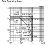
realy the DV44VHG?..if i look at the SOA it is at about 20 Volt just 1,5 Amps just impulses with 1msec is better.
BDW93C and BD911 and complementary are mcuh "better " at that .
it because of the flat hfe curve or not?
kr
chris

i rally do not want to be more "inteligent" than you but...
realy the DV44VHG?..if i look at the SOA it is at about 20 Volt just 1,5 Amps just impulses with 1msec is better.
BDW93C and BD911 and complementary are mcuh "better " at that .
it because of the flat hfe curve or not?
kr
chris
Hi, this is one of those that make indoor music at decent level without fuss. I built few, without fuss ..again.... ever. Cheers!
Only thing I would suggest is to configure output as Sziklai instead of Darlington, bit more headroom and easier thermal coupling.... Frankly, I did not do sziklai yet, its in pipeline...
Always fun, Good Idea for opamp driver with complete auto bias I used a Boot strapped Diamond filter.
And yes used a CFP/Sziklai for final output stage.
By doing this no additional drops are needed. the power transistor stays outside the thermal loop.
Using all similar T0126 devices for the diamond they all thermal track on same heatsink no bias adjustment ever needed.
As with a Darlington stage added to a diamond you still need additional drops and bias can shoot to the moon (unless desired)
and more difficult to design around
I have example with higher voltage opamp in lineups thread here post#136
T1-T4 thermally linked and the CFP uses light Degen for stability and thermal stability.
I used 2 power transistor pairs for relentless drive to 4 ohm loads
These are low frequency switching devices.BDW93C and BD911
911 is 3 MHz 93 not listed = likely 500 kHz or less much like tip31 and many others.
T0-220 can be rated from 40 to 90 watts
It is good your aware of soa curves
you will soon fine they are all limited to 1 or 1.5 amps at high temperature
DV44/45 were chosen for high gain and high ft 50 MHz
With simplified amplifier such as JAT
low distortion at high frequency isnt a issue. hardly likely to exceed .1% THD20
If shooting for low distortion with optimized circuits to even touch .01 to .001% at high frequency
you will need different devices.
I do agree, but even in your thread I mentioned it is possible to just jump away from even considering T0-220 as a whole
for power transistors. Realizing their limits I often used 2 pairs even 4 pairs in amplifiers for a work around.
Then again right away the critics come rushing in, Why? 2 or 4 pairs use a bigger transistor. yeah of course.
dont worry I have found 50 MHz 230 watt devices, and their is always something wrong with them.
50 watt or 80 watt T0-220 they get derated at temp.
If I use a fast 80 watt someone will tell me a 50 watt is better etc etc.
Id rather toss in 2 pairs, if I showed this, right away.... ( The internet) why you using 2 pairs ? yada yada yada.
As mentioned I had a lot of fun with 89 cent BDW93, I stacked 6 pairs just to hear the internet yell at the clouds...
Maybe ill drive them with a 7171 opamp...lol wait till you read that one.
Anyways, I agree for the most part, if noticed using 30/35 volt rails in post #9 Im using 2 pairs of output devices.
That would be my usual approach, relentless drive and SOA with 4 ohm loads. Surprised nobody said anything about that either.
at 25 watts it will be holding .008% distortion at THD20, this little guy, it is past or hitting crest at .01 to likely.1% at that power level.
Last edited:
That s basicaly what i use for my PC but with only 32V total supply, darlingtons are Sanken MP1620/MN2488,
otherwise BDW93C/94C are also a good fit given their very low cost and their 20MHz Ft and decent SOA.
otherwise BDW93C/94C are also a good fit given their very low cost and their 20MHz Ft and decent SOA.
Attachments
Last edited:
Cost is great, my local electronics store had them in stock too. No internet orders. Could just pick them up.very low cost and their 20MHz Ft and decent SOA
Never seen data for 20MHz if that is what they are. They are more than fine.
They are both 80 watt transistors.
Yes exactly, I just wanted a neat little amp for simple systems. Real power used be 5 to 10 watts for most people.
For desktop or high efficiency wideband speaker. I dont even bother with even 4 ohm loads.
plenty people run LM1875 for years, it is basically single T0-220
for DIY builders looking for small fun tiny discrete amp, small transformer power supply.
A simple T0-220 pair is more than fine. 50Mhz and good gain all good
I dont care to nitpick 40 to 80 watt packages 1 to 1.5 amps is the end of the road for all of them
Hi Whitdragon
i rally do not want to be more "inteligent" than you but...
realy the DV44VHG?..if i look at the SOA it is at about 20 Volt just 1,5 Amps just impulses with 1msec is better.
BDW93C and BD911 and complementary are mcuh "better " at that .
it because of the flat hfe curve or not?
kr
chris
View attachment 1407502
44/45 VH versions are no better than the H version for SOA, I just use the smaller ones. It’s what limits the supply to +/-20 ish volts. DO NOT use them at 30. But at 20V they stomp MJE1503x. The beta holds up better below 10V. One and a half extra volts of swing out of 18 is stomp, BTW. Car amp chips lived or died by how close they could get to the rails, six tenths of a volt was a market differentiator.
Hi Whitedragon
NE5534 should have 15Volts at the rails. sorry but for me it is not clear how you "loose" 7 Volts with R5 and R15 (each are 8.2R) in the positive rail ?
kr chris
NE5534 should have 15Volts at the rails. sorry but for me it is not clear how you "loose" 7 Volts with R5 and R15 (each are 8.2R) in the positive rail ?
kr chris
For very good stability I add a little impedance then decouple with large 470u caps before the bootstrap current source/bias section.Hi Whitedragon
NE5534 should have 15Volts at the rails. sorry but for me it is not clear how you "loose" 7 Volts with R5 and R15 (each are 8.2R) in the positive rail ?
kr chris
Then especially before the op amp add a little impedance then standard 10u / 100n decoupling caps.
Any power supply current surges wont cause any stability issues.
Often missed with many " simulations" in real life is a issue.
Itsy bitsy little traces to the opamp might help people get lucky enough since small traces have resistance 8.2 ohms guarantees that.
Might help clean up the rail a little with unregulated power supply. Not claiming it does.
Its stability, so I decouple the bootstrap current source section, and the opamp.
Depending how well the model is for the power supply pins, Atleast with TinaTi models and adding internal resistance to the power supply.
If the model is not decoupled from the supply it will show stabilty issues. So adding decoupling even in the model is needed.
Real life for sure. Or atleast it is how I model. I dont use " ideal" voltage sources set to 0 internal impedance or a perfect endless power supply.
I test at usually 1.3 ohms internal resistance. Then at least decoupling capacitors do something in sim. or are needed like real life.
I often crank it up to 10 ohms for supply resistance. Then blast the amp full power into 4ohms at 20kHz.
And yes many amps will be " stable" at 0 ohms, and then act different with less ideal power source.
Why I use TinaTi and like many of their Opamp models which are different for TINA than generic pspice models that TI provides
for opamps.
5534/32 get noted as max voltage of 22 volts or 20 volts, data sheets vary.
So any voltage drop is needed just in case the unregulated power supply jumps above 22 volts with no load, the opamp is safer.
Might need to raise the voltage.
Their wont be a 7 volt drop, in that model im probably maxing out the highest voltage you would take a 5534/32 too.
Main concern is if you were driving a low impedance load in real life like 1k or 600 ohms.
Then you would never run a 5534/32 at 20 to 22 volts. It is not really the voltage but the max current of the chip.
In this circuit AC current on the opamp is in under 1 Micro Amp if I remember. You could launch the chip to max voltage.
It is driving a very easy load.
With decoupling capacitors the voltage drop is close to nothing could likely raise R15/ 17 higher.
Internal resistance of the power supply is 1.3 ohms in the model. With 21 volts in for power/ the opamp has 20.75 volts.
Lets assume the transformer is a little 100va transformer.
Unloaded with poor regulation of a small transformer is might be 23 volts even higher unloaded.
Then if it sags to 19 volts loaded, internal resistance of the secondary could be considered. around 15.8 ohms ...ish.
Dont matter we can just use the sim to sag the supply. Ill set it too 21 volts then raise the impedance way beyond 16 ohms
to 27 ohms and show you power in/ and power to the opamp.

There yah go, 19.5 volts in and 19.39 volts to the opamp.
So no your not losing 7 volts to the supply decoupling.
They could actually be a little higher for R15/17
Just dont know the unloaded voltage of whatever transformer being used after its rectified.
Obviously the only concern is not to exceed the opamp max voltage. Having higher voltage to the output section is not a problem of course.
Last edited:
- Home
- Amplifiers
- Solid State
- WD-5534 op-amp Driver 25 Watt T0-220