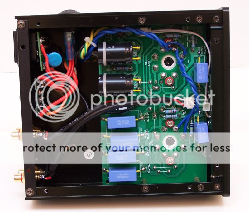
Mullard 3-3 . The more unknown versions

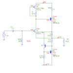
This schematic are most likely a earlier version of the well known mullard 3-3 amplifier using different tubes than the the later version we all know real well (EF86-EL84) . This version uses EF40 as the pretube and EL41 as power output tube.

Enjoy 🙂

Phil_EL41_3_01.jpg

Phil_EL41_3_02.jpg

Phil_EL41_3_03.jpg


Btw . There is a third version of the schematic too that uses EF36 or EF37(A) and EL33. But i have not found a schematic yet on this version.

Speaker measurment mic arc

I would like to get polar data for my speakers but a lot of my speakers are large so a turntable is quite impractical. Instead I would like to build a 90 degree microphone arc with 5 degree spacing (18 microphones) at a radius of 3m and use a multichannel interface to capture the sweep. This would look similar to the Dynaudio measurement chamber:
Dynaudio: inside the speaker corp's state-of-the-art measurement facility | Home Cinema Choice

it would be very expensive to purchase 18 commercial measurement microphones, however I have constructed a microphone in the past using these instructions:
System Test
the WM-60AY capsule is no longer available though. Is there a modern replacement? perhaps MEMS?

Toroidal- not all wound the same?

In fiddling with my composite amp ive found out that two of my toroidals dont sound the same.

One is an antek 300va 24 0 24 0, the other same spec but a local korean brand. They weight about the same. The amp uses lm3886 for output and a simple C filter (not crc)

Simply put the antek sounds much better. The bass is bigger, theres better grip on the lower notes. The korean transformer sounds tinny in comparison as if the power has been halved.

I couldnt get much out of how the korean toroidal was wound except that their core is outsourced (so probably cheap chinese) and they have hum issues (primary wound close to saturation?)

What would differ in a good and bad quality toroidals and how would that affect the bass in a class ab amp?

Thank you for your input in advance.

Newbie question about phono signal from cartridge

My question is: why are all the output sockets I see in all turntable phones all single-ended? Why are they not balanced?

I was under the impression that if
  • you have a floating differential signal,
  • the signal amplitude is low, thus making it vulnerable to noise pickup
you have a textbook case to want to feed the two wires to a differential input of a balanced or differential amplifier. And I was under the impression that all cartridges, like most (passive) mics, are passive transducers which will generate a differential or "balanced" output. Basically, phono cartridges and XLR connectors and balanced interconnects and XLR inputs to phono preamps seem to be a match made in heaven. This is certainly true about mics and mic preamps.

Yet, I find all turntables fitted with RCA sockets. None of them (that I've seen) are balanced. (I'm sure there are a few, but that's not my point.) Why? Is my understanding of what constitutes a balanced signal incorrect? Is there some other reason why all turntables and phono preamp inputs in the world do not do balanced connections?

I tried searching, but couldn't find anything which discusses this. Maybe my searching was inept.

Easy and quick way to glue mylar to aluminum?

I've been dabbling in alternative technologies for a while now.
Usually they involve gluing 1um thick mylar to something.

I have very rarely been able to make anything close to a perfect diaphram.

For starters getting the mylar to be taught without wrinkles and without ripping the mylar is..somewhat of a challenge.
I currently just unroll the mylar and kind of stretch it out onto a mirror and kind of hope for the best and gently push the wrinkles and bubbles out.

Then I apply super 77 to it and apply the aluminum.

However, this is crude, annoying, slow, and imperfect.

I've tried ordering rolls of metalized mylar from china but they always tell me something along the lines of "sorry this is meant for capacitors" and then shut me out completely, the moment they get a hint that I am doing something unusual which is hard to avoid because they ask for a bunch of capacitor related technical parameters that I don't need or don't understand.
I'm not sure why they just don't take my money...

In any case. How would a professional do this?
Is there some contraption I can use to accomplish this quickly and easily with perfect results every time?

Bunch of JBL Cabaret Stuff in Denver

Hi All,

I noticed an ad on FB marketplace that may appeal to someone. This isn't my stuff. I don't know the guy. But I have been super curious about some of these things, so maybe you are too:

JBL 4628B- $300 ea., 4 availablec
JBL 4695– $550 ea., 2 available
JBL 4699B - $650 ea., 2 available
JBL 4625B – $200 ea., 4 available
JBL 4602A - $350 Each, 4 available
JBL 4691B Cabaret Series Speakers – $300 ea., 4 available

The link is here if you have FB: Log into Facebook

I'm working hard to not buy a pair of the 4628Bs just to check them out.

Paul

  • Locked
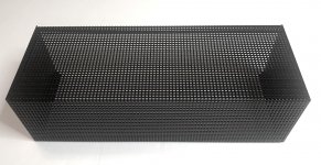
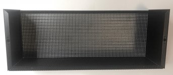
FS: HK Citation II Cage (Reproduction)

FS: HK Citation II Cage (Reproduction) $79

This is a brand new, high-quality, heavy-duty cage for the Harmon Kardon Citation II Amplifier.

It is professionally painted black. Attaching hardware is not included. The price of steel has tripled in the last year or so, and this unit is sold below cost.

I have a source for the hardware kits -- about $18.00. PM me if interested.

$79 + shipping

Attachments

  • Cit II cvr out.jpg
    Cit II cvr out.jpg
    800.4 KB · Views: 247
  • CIT II cvr ins.jpg
    CIT II cvr ins.jpg
    729.3 KB · Views: 236

The verdict is in - VFET amplifiers are terrible

So, I've had my VFET amplifier since Thursday and it's now Sunday morning. It has cured my Audiophilia Nervosa (i.e. FOMO) but a worse complaint has set in. I have incurable insomnia! That's right, I've barely slept in days!!

I keep thinking about my music collection, most of which I haven't listened to in 15 years, and wondering how this album or that album will sound. So far I've gone through Michael Franks, Jennifer Warnes, Stanley Jordan, Bill Withers, Thomas Dolby, Ricky Lee Jones, Steely Dan, the Doobie Brothers, Ryuichi Sakamoto and all my test albums. I've started buying CDs again just to hear how they sound.

How can I make it stop?? Argh!!!!
  • Like
Reactions: mjw21a

Variable DC power supply to drive TT motor

variable DC poewr supply to drive TT motor

Hi all,

I'm looking for a stable lab varible DC power supply to drive a Maxon A-max motor driving my TT.

Found one for sale with:

Ripple & Noise: <1mV rms
Waves and noises: CV<0.5mV r.m.s, CC 3mA, r.m.s
Power effect: CV < 0.01 % +1mV, CC <0.2% + 1mA
Overload effect: CV<0.01% +3mV, CC<0.2% +3mA

could such a supply run my platter good and steady?

Thanks all
Ik

B9E Novar socket for USA large 9 pin tubes with 1 mm pins.

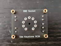
So after seeing some of the threads on here, and seeing many tubes that would be useful but not finding any sockets, I've designed a PCB based socket for them.

It uses a set of nine Keystone 1434 as the socket pinholes. They are easy to desolder in the event they wear out.

The connections are made to screw terminals.

There is a centre hole to make drilling the chassis easier, too. EDIT: The hole is 3mm. I now know some Novar tubes have the evacuation tip on the bottom. The hole can be drilled out if needed.

To the mods - Move to Vendors if necessary. I post this in parts so people will see it.

Oh, and Happy Wednesday.

Koda

Attachments

  • Screenshot from 2021-10-20 15-07-41.png
    Screenshot from 2021-10-20 15-07-41.png
    197 KB · Views: 366
  • 2021-10-20 14-54-47.jpg
    2021-10-20 14-54-47.jpg
    711.2 KB · Views: 344
  • 2021-10-20 14-53-54.jpg
    2021-10-20 14-53-54.jpg
    733.9 KB · Views: 391

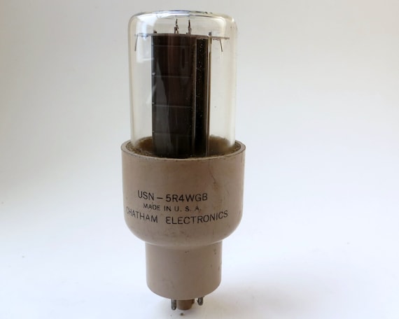
5R4 v 5C3S / 5U4G for RH84 v.2 amp

Hi all,

I am in the process of putting together the parts for my RH84 V.2 EL84SE valve amp.

RH Amplifiers: RH84 amplifier - revision 2

I will be using NOS Russian 6P14P-EV in place of the EL84s.

The suggested rectifier power supply by the designer is a 5R4
RH84+-+rev2+CLC.png


il_570xN.2594012707_jasi.jpg

The datasheet is here
http://www.r-type.org/pdfs/5r4gy.pdf

I was wondering about using a Russian 5C3S which is being advertised as being equivalent to a 5U4G.

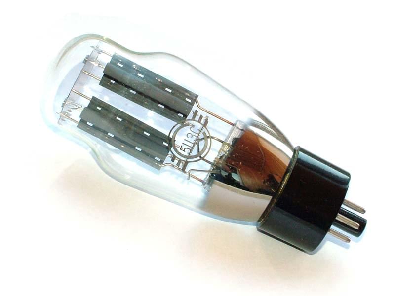
5C3S-.jpg


Russian tube 5C3S is a quality equivalent of the 5U4G. Military equipment, high reliability. Svetlana factory. OTK marking.
Name: 5C3S
Type: double-anode rectifier
Application: alternative current rectification
Cathode type: oxide, direct heating
Envelope: glass
Mass: 72g
Filament voltage: 5V
Filament current: 2,7-3,3A
Anode voltage: 75V
Anode current: 0,225A
Socket type: rsh5-1
Max.reverse anode voltage: 1,7kV

The data sheet is here
https://drtube.com/datasheets/5c3s.pdf


The reason is purely down to looks of the tube at this stage. I have tried using the PSD2 software but I am such a novice I am not sure if I have done it correctly.

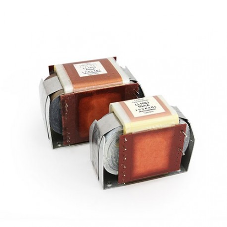
I have bought Lundahl LL1663 SE OPTs

lundahl-tube-amplifier-output-transformer-ll1663-pp.jpg

http://www.lundahl.se/wp-content/uploads/datasheets/1663.pdf

and a Toroidy 10H 250mA toroidal choke for the amp project and will be using 8ohm speakers.
2831.jpg

TDS10/250 - Toroidal Choke 10H 250mA DC - Shop Toroidy.pl

I am thinking of using a Hammond 372DX Transformer with
600V CT@144ma, 50 VAC, 5vCT@3A, 6.3VCT@4A which is a bit overkill but would enable PSE in the future I think.

The B+ is 315V

Can anyone advise on the choice of Rectifier tube and any changes to the capacitor values that may be needed to make this work if possible run the PSUD2 software to check the values for me. If it is a no and not worth doing then please do say

If this is in the wrong section could admin move it to the right section?

Thanks for all your help.

Lee

What mids/widebands to choose

Hi,
i feel like i need to add the 3rd drive into my 2way JBL GTO 609C front doors set. I will custom install it into the A pillar, the tweeter i would probably let them in factory triangle on the door because they would be alligned but would make a custom mold also for better aiming.
The tricky part is what driver would i choose. I don't want to spend very much on these (even tho i know they are crucial drivers regarding clarity).
To keep install ok i would need 3" drivers (4" would be too big)
I have seen real budget speakers from 10USD to 60USD (a bit much for me at the moment).
What brands from the following will i be best with:
Visaton, Lavoce, Dayton Audio, Hivi, Fountek, Monacor, Tang Band and Peerless
From specs, some are even widebands.
They will be amplified (even though i've seen these requiring 15-20 W RMS most)

thanks.

Identifying a dead/missing trimpot

Hi everyone,


This is my first post here, so if I'm doing something wrong, I'm sorry!


I'm repairing an old organ, the previous owner tried to tune it and destroyed what was probably a trimpot (which is now totally missing).
According to the schematics, the part "number" or "name" is "23.515".

I've found pictures of the missing component: Infrequent Sound [sex.tex] technology: GEM Galanti Group Rodeo 49, made in Italy
My missing part is the bottom left potentiometer.

Does this "23.515" refer to something standard ?

Thanks for any advice!

Power requirement?

Greetings all,

I have hesitated to which sub-forum to post the topic, but as it is relevant to a low-frequency part of a multi-way speaker, I believe that this sub-forum is the best.

Background

For one reason or another, I had to give away my fully horn-loaded system and live with headphones. I am now in a position to acquire/build a pair of speakers, though not by replicating my former system. I have been contemplating a three-way, preliminarily a MEH above a 15 inch low-frequency driver. I seem to have a preference for a sealed box; which may well be because something always bothered me in a certain frequency portion of ported box. So, I will limit the following drivel to that topology.

Problem definition/proposed standard

From my understanding, one of the criticism of sealed box, and I am paraphrasing, is a “lack of low frequency extension and low efficiency”. Admittedly, this is a rather ill-defined statement, so let me attempt to qualify it vis-à-vis my preferred music genre.

As I tend to listen mostly to classical music, I have found two topics that appear to be relevant: “What high efficiency speaker for Classical Music?”, https://www.diyaudio.com/forums/multi-way/292232-efficiency-speaker-classical-music-26.html, and “A Test. How much Voltage (power) do your speakers need?”, https://www.diyaudio.com/forums/multi-way/204857-test-voltage-power-speakers.html.

I understand that different people may have different opinions regarding the required SPL, still, given the title of at least the first topic, one would expect at least some commonality, but the amplifiers range from a 2A3 to high-power solid state, and associated differences in the amplifier’s power.

In an attempt to understand the power requirement, I propose the following. According to my understanding majority of classical pieces do not have much content below about 40 Hz. Of course, there are exceptions, e.g., P.I. Tchaikovsky - 1812 Overture; R. Strauss - Also sprach Zarathustra; some G. Mahler pieces – 8th symphony, but they are that – exception. Since I live in a quiet environment and my listening preferences are on average 80 dB or less, assuming that the dynamic range of classical music is 20-30 dB it follows that 110 dB at 40 Hz peaks should be the standard.

Method

1. Driver selection

My first naïve idea was to look for high-efficiency 15 inch drivers, but, as I quickly found, they have about the same efficiency, cf., Table 1. So this does not appear to be a silver bullet.

2. Required power vs Vb

Recalling J. A. Hofman’s “iron law”, I decided to investigate the relationship between an enclosure’s Vb and a power that would satisfy the above-proposed standard. I started with Vb=100l, not due to any sophisticated reasoning, but simply because I had built such an enclosure; the idea having been that I had to start somewhere, and by comparing a model for the specific Vb with a measurement, it may be reasonable to correlate to different volumes.

Using Unibox v. 4.08, I had adjusted the power to the required SPL at 40 Hz. I repeated the exercise for different volumes, cf., Table. 2.

Notes: (i) Table 2 summarizes the model without any consideration for a room gain;
(ii) I was not concerned about exceeding the Xmax for the frequencies below the 40 Hz as this is an implementation and not conceptual issue.

Conclusion/Discussion

1. The parameters Fb and even more F3 are not strongly dependent on the change in Vb;
2. There is an inverse relationship between the Vb and the Qts;
3. There is an inverse relationship between the Vb and the power, which agrees with the “iron Law”; and
4. There is no escaping the conclusion that, assuming that the above-defined standard is to be achieved, a power higher than presented in the links is needed.

Provided that the conclusions are correct, and please do not hesitate to point any flaws in my diatribe, the above now presents at least two questions:

1. What would be the best architecture for an amplifier that will be most of the time supplying power 30 dB below peak, considering preliminary frequency of operation 40 Hz – 350 Hz?; and
2. Disregarding WAF, is there any guidance on selecting the Vb, considering the Vb to Qts relationship?

Kindest regards,

M

Table. 1

Driver Fs [Hz] SPL /1W/1M [dB]
TAD1601A 28 97
TD-15M 34.7 97.8
JBL2226 40 97

Table. 2

Vb [l] Fb {Hz] F3 [Hz] Qts Max SPL [dB] Power [W]
101.7 56.1 60.81 0.655 116.30 155
111.9 54.15 60.81 0.632 116.30 145
122.1 52.47 60.26 0.617 116.10 140
132.3 51.01 61.38 0.601 116.00 135
142.4 49.72 60.81 0.585 116.00 130
152.6 48.57 61.94 0.576 115.60 125
Blown Varistor in Myriad Integrated Amp

Hello all,

I have a Myriad Mi Integrated Amp that has been running well until recently. It hasn't been used for about 9 months and the first time I was listening to it after that it was fine for about 20 minutes and then the amp wend dead, I heard an on-and-off 'buzzing' noise for a few seconds, and then I saw smoke. I pulled the plug and opened it up.

After some investigation it seems that a Varistor (one of two) has blown. In the attached image it is circled in red, it is labelled 'VDR2' on the PCB, the second one is circled in yellow and labelled 'VDR1'.

All other components seem okay to the naked eye.

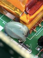
The two Varistors seem identical. Due to the location of the blown one I can not make out all the markings at the bottom but comparing it to the markings on VDR1 they seem to be identical components (see attached photos). The text that I can clearly read states "ZOV 14D471K (various certification markings) CH52Z".

Some observations that I found interesting were that (a) the two Varistors seem to be identical yet the blown VDR1 is a paler green to the good VDR2, and (b) the failed VDR1 had some heat shrink completely covering it which burned through when it failed.

As I understand it these Varistors are a layer of protection in the circuit to protect from over voltage spikes. Is it logical to assume that this was the cause or could it have just failed independently? If it is likely to have failed due to over voltage would that be coming from the mains supply or a failure upstream in the circuit?

So I have a few questions:

  1. Is the colour difference likely due to heat during or leading up to the failure or maybe a different batch, a potential cause of failure?
  2. Why would there be heat shrink over only one of the Varistors and not the other? Could that have caused overheating and premature failure?
  3. Can I just replace the failed Varistor with another ZOV 14D471K (of any manufacturer), turn on the Amp, and see what happens?
  4. Finally, whilst I'm 'in there' is there any point at all replacing and upgrading any of the other components - Cap upgrades for example?
I look forward to your thoughts and advice.

Attachments

  • PCB.jpg
    PCB.jpg
    1.1 MB · Views: 326
  • VDR1.jpg
    VDR1.jpg
    447.2 KB · Views: 274
  • VDR2.jpg
    VDR2.jpg
    391.1 KB · Views: 223

Quick question about grid stoppers

I picked up two hundred 1W 270R carbon composition resistors for a $2 at a ham swap last month. The resistor body is 15mm x 5.8 mm. I was going to keep them as my "lifetime" stock of grid stoppers...

Is there any rule about not using 1 watter's as grid stoppers? They should have no difference than 1/2 watter's in that position no? They certainly have twice the carbon 🙂

Cambridge CXC Transport Mod Help!

Greetings everyone,

I watched this CXC mod video:

[wiki= https://www.youtube.com/watch?v=VoxC3st7WQw]%[/wiki]

And following, relocated the two cables and put a book on top to deal with resonance - these changes made a noticeable difference. I intend now to apply the resonance dampening material inside and will solder in a BNC connector. Near the end of the video, Miguel suggests adding a capacitor to the output, but, no details are given. Has anyone any idea what he’s suggesting, where this cap would be installed and what value?

Any and all information appreciated.

Thanks,

John

My first DIY PA System

Hello everyone !
Here is an updated build or my project :
I want to build a portable "boombox". I must insist on the "portable" as I don't have a car nor a bike. I'm tall and still in "good" shape so I think I can easily move around 15Kg (and If I can't, I'll just use a small trolley, or go to the gym 😀). Usually parties are outdoor, playing for 6hours, for 50-100 people. It won't be the only speaker, it's to support an already existing setup with several boombox (sometimes only one Aiwa Exos-9, which is not enough, that's the main reason why I want to build it). My budget is between 500€ and 750€. I live in France and the wood I can get would cost me around 50€-100€ for MDF (which I entend to use).
I'm not looking for perfection here. The project is basically a cheaper soundboks gen. 3.
Thanks a lot for the help 🙂

Here is the new build :
Mid/bass 10" drivers : Eminence Beta-10A – Thomann France x2
Tweeter compression 1" : Celestion CDX1-1010 – Thomann France
Horn. : Celestion H1-8050 – Thomann France
DSP 2x4: miniDSP Kits: miniDSP 2x4 kit
3way amp : WONDOM AA-AB35281 T-Amp Class D Amplifier Module 3x200W 3 Ohm - Audiophonics
36V battery : https://fra.grandado.com/products/3..._BwE&variant=UHJvZHVjdFZhcmlhbnQ6MjA1MDY4NDg3

Let me know what you think. 🙂

Simple High Performing Headphone Amp

Hi All

I just wanted to share this unit gain headphone amp circuit I designed and built it on Sunday.

So far it has exemplary performance and specs considering its simplicity, the built version exceeded my expectations:
Even thought I show a cap in the circuit, if the JFET's are matched the circuit is DC coupled input to output. I built 2 channels and 1 channel has 4mV DC offset andthe other has an 3.4mV DC output offset
The frequency responce is crazy I measured the responce to be almost perfectly flat with 0dB from 10Hz to 1MHz into a 33R resistor.

The specific JFETs isn't critical as long as IDSS is greater than 3mA and they are matched. I simulated with 2sk170GR, 2sk246GR/BL but I built it with 2sk117Y's (the model of the 2SK117 wasn't good).
The output bias current it set by 0.65/R75+R76, in the built version I went with R75 and R76 5R and R50 10R so it didn't run too hot.
I put it in a box last night and listening to Leonard Cohen with it now.

Have to give credit to Nelson Pass for his constant current stage and Erno Borbely for inspiration.

Cheers

Tim

Attachments

  • Headphone amp 3.PNG
    Headphone amp 3.PNG
    14.9 KB · Views: 3,312

How to perfectly smash an octal tube!

Well I pulled a 6AV5 out of a box of tubes that was on my bench, but the other end of the tube box didn't have a cover flap. So the 6AV5 slid head first 90 degrees onto a hardwood floor from a height of 3 feet. It shattered. But it shattered perfectly out of its base, meaning there were no shards sticking out of the octal base, smooth all around!

So if you're thinking of smashing an octal tube this is definitely the way to do it. Years a ago I remember hitting one from the side with a tack hammer. All the shards were still sticking out of the base, and I probably smashed up the insides, and plenty of glass remained, not good. This dropping on its head method removes every bit of glass and the insides unharmed.

HowToBreakAnOctalTube.jpg

New Tube Kitset from RedRoo

Hi all. Just letting you know that I've redesigned the RedRoo 5W SE amp to use a powder-coated steel chassis.

I'm also now offering it as a kitset (less the valves and external 12V transformer which many people will already have lying around).

If you want to roll-your-own chassis or use a timber case there is a version with a precision-drilled top plate only.

Or you can download the full design for free from the website, and maybe just purchase the pc board.

Take a look at DIY Valve Amplifier kitset at DIY Valve Amplifier kitset

Phil

Roland JC40 Question

Hi all,

I just had a question about the effects loop on a roland JC40. Could any damage be caused by using this as an auxillary input (with my phone)? I've use my phone for a metronome app when I practice through headphones but am afraid to continue doing this out of fear of damaging components of the amp. For clarity, my instrument is plugged into the front input channel, headphones through the headphone jack in the back, and phone plugged into the effects input loop on the back side. Thanks for any input.

C

A new hope ... for some old gear

Hi all,

I am proud to say i've finished a Hugh's project once again. This was a particularly different journey, given i decided to dig up some treasures found in the attic , stored from past ages, but nevertheless one of the most fun to do ever.

I should start to say thanks to Hugh.R.Dean, as this is THE man.
He is behind all this, and of course i am mainly the workforce in a job where the brains is all that matters. Hugh has kindly given my support during this assembly, particularly hard thing to do from the other side of the world about a design thought more than 15 years ago. This is proof of Hugh's commitment to people and to his work. Praises.

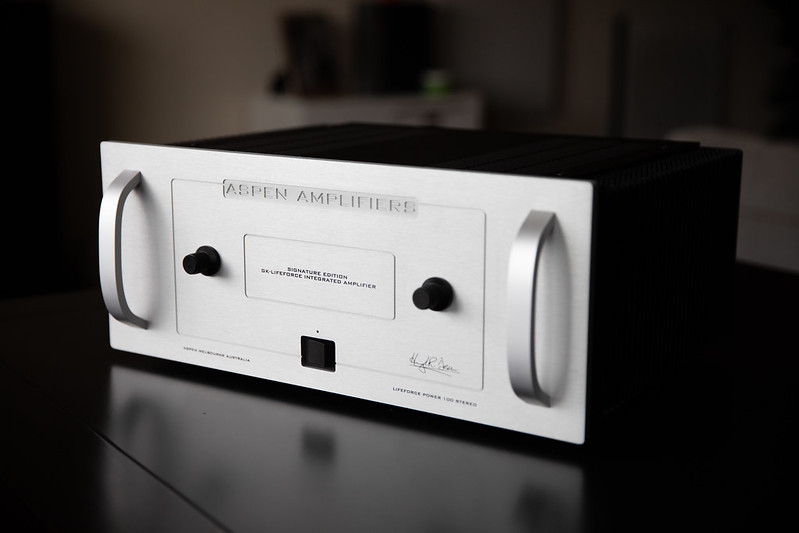
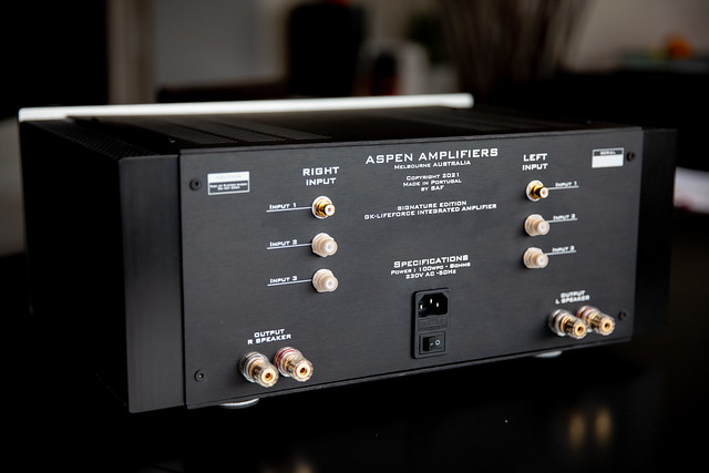
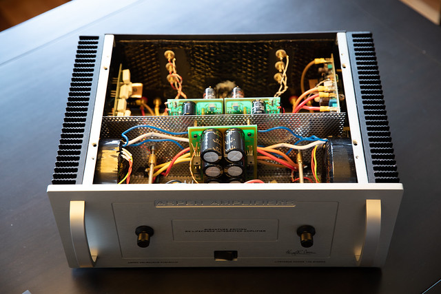
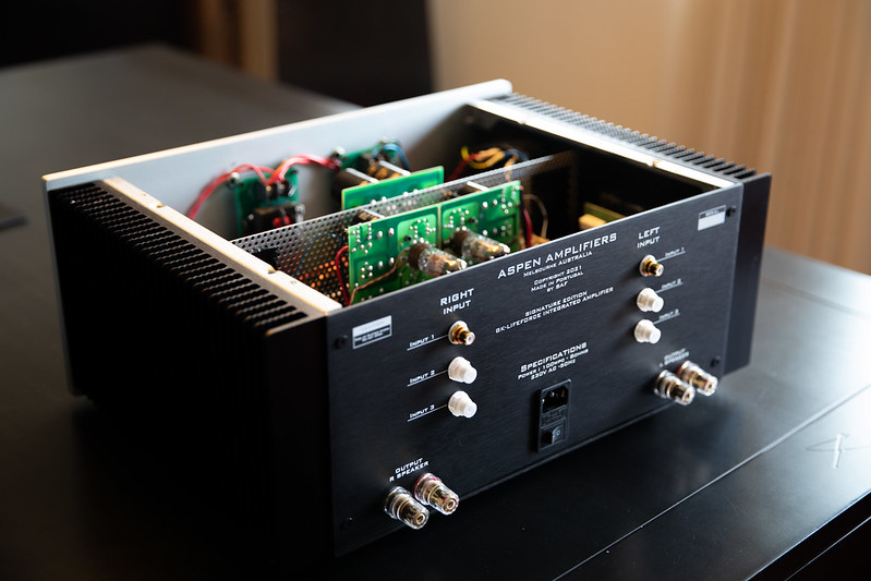
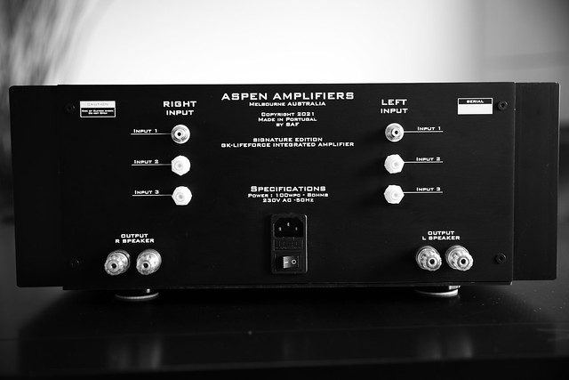
So this is my GK-LIFEFORCE.
A tube-hybrid preamp and power amplifier built around a GK-1 and a Lifeforce 100.

51641611109_942f370206_c.jpg


I decided to join these 2 products together and mount them in the same chassis, however they are fully independent right down to their AC power input. Built from scratch, i had to source and buy just about every litle part.
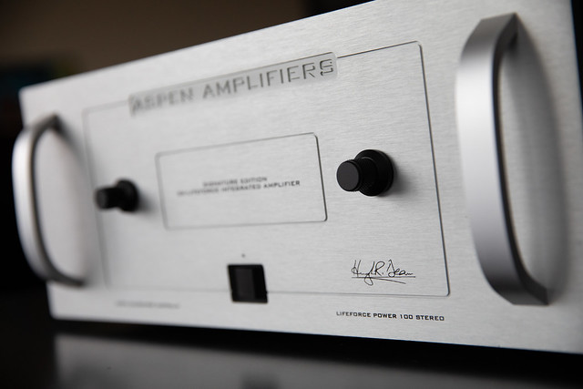
It has the same look&feel of my previous designs in the past, right down to Hugh's signature on the front fascia. My tribute to him reamins. Kudos again and again

51641808535_784fc6f4f6_z.jpg


It features 3x inputs using an ELMA rotary switch and a ALPS 20K volume pot.
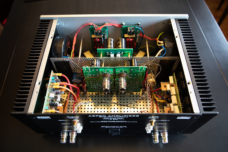
There is an independent AC filter conditioning ( FO-FELIX by FOLSOM ) for the GK-1 and the LIFEFORCE.
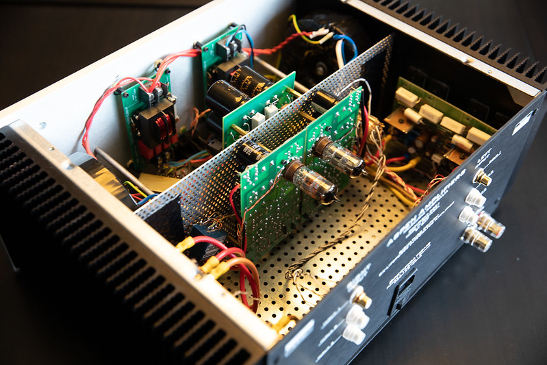
The Lifeforce was built with its power transistors flip sided so they can directly coupled to the large heatsinks that make up the chassis. This proves to be a very efficient solution, it barely warms up.

51641809170_4ea22e1286_z.jpg


51640960741_98f3326c85_z.jpg


51641810660_ba1fbb2c0a_c.jpg


Chassis was built with a perforated steel plate separating the AC from DC side (more or less). AC side has filters, transformers and power supply. DC side has the power amp pcbs and the preamp board (split in 2 😀 )

51640961821_ccbb3c8780_c.jpg


51641811975_1bd6917d98_c.jpg


I plan to add little extra in the future. I use a raspberry pi + HAT DAC for source. As this is really small and i still have space inside the chassis close to the inputs i was thinking to built it as a 4th input. Only worried about possible wifi noise going into the tube sensitive preamp. Maybe someone can share experiences ?

51640963506_eba5130b8b_z.jpg


Not bad for 6 months work? At least I am happy with it.
All the best
Filipe

Power supply question

This is the followup from:

Schematic hunt: RIAA Phono Preamp

It took me a little over a year to round up all the parts, but mostly just to find some personal bandwidth to dig into this in earnest. I just finished prototyping the tube rectified LCLC power supply found at the bottom here:

RJM Audio - Tube passive phono preamplifier

I followed every component spec to the letter with the only exception being the transformer is 620VCT vs. the specified 625VCT, but the 0.8% variance is almost certainly less than the manufacturing tolerance.

Hammond 372X datasheet:
http://www.hammondmfg.com/pdf/EDB372X.pdf

I fired it up, and checked the output immediately (didn't wait for it to warm up in case I screwed something up). I should see 250-300V from B+ to ground, but I'm actually getting 475VDC!!! Something is very very wrong. Blow up components wrong! Or I'm just an idiot wrong... Very much a possibility here. First rodeo of this sort.

My Fluke is only good for 600V AC/DC, so I can't test for the 620V output of the transformer secondary coil, but I can test from each of the 310V sides of the 620VCT output coil to 0V, and they're giving me 348V. That's ~11% high, and probably within manufacturing tolerance*. My mains current is 123V as of just now (I used the 120V blu/brn and wht/blk leads for the primary coils).

What could I have messed up and how to get such a high output voltage from this power supply?

*Looking closer at the transformer datasheet, I see that the wiring setup for what's supposed to be 620VCT is actually expected to output 340.0V +/-2% with 120V, which is very close to the 348V I got, but not at all the 310V printed elsewhere on the same datasheet/half the 620V that's on the sticker on the physical component...?

Need help finding power transformer datasheet?

Hi all

I have recently acquired Nelson Pass' M2 kit, and as such I have decided to build a proper power supply to compliment it.

A friend of mine gave me an MCI 4-05-5602 transformer. The only problem is that I cannot find its datasheet, let alone any evidence of its existence.

Here are some pictures of the actual transformer...
Imgur: The magic of the Internet

If anyone could help me find its datasheet or provide any info on it I would appreciate it a lot!

Terminated transmission line for midbass?

I'm intrigued by what I believe is called terminated transmission line...I mean a transmission line inside a sealed enclosure, to be used for the midbass within an active 4-way system.

A couple of sealed subwoofers take care below 80hz. The midabass would cover 80 to 450Hz or so, in a sealed enclosure. Midrange and tweeter would be in sealed boxes too, I think.

Is the midbass a good range for TL? I understand the back wave of the driver bounces back against the back of the cabinet (assuming a flat, vertical surface) and out through the cone itself, out of phase. This generates distortion and is most prominent at frequencies where 1/4 of the wavelength equates the depth of the cabinet. At 80Hz the 1/4 wave is 108cm long, at 150Hz it's 57cm, and at 300Hz it's 29cm. So in my mind midbass is where TL ought to be applied. Am I right?

Are the gains worth the trouble of building this? Maybe I'm conceptually correct but this is not material enough?

Alternatively I could build a quadratic residue diffuser against the back wall to break down the back wave, or even simply place a very large chamfered piece to scatter it.

FWIW, some midbass woofer alternatives under consideration are twin Beyma 10G40 per side (each in its own enclosure), or one 12P80Fe or Nd per side.

Looking forward to your input!

Onkyo A8800 broken tone controls - where to start?

I recently picked up an Onkyo A-8800 from someone who said the "digital filters" were broken. I thought he meant there was something up in the DAC board but it turns out the real issue is when the selector dial is turned from "direct" to "tone" the left speaker channel cuts out except for very high frequencies, and when turned to "tone + processor" both channels get very distorted. I'm decent with electronics but have never taken apart an amplifier before -- where should I start?

Is the front-end of an amplifier usually the same as a preamp gain stage?

I'm thinking specifically of how the BA-3 front end can also be used as the core of a preamp. Is this usually the case, at least in principle if not practicality? More generally, would it be beneficial to remove this double gain and make either the preamp or power amp input passive, to reduce the total number of gain stages?

Amazon amp quirks - attenuator static

Hey folks, I have a Fosi Audio class D amp that's been on my PC desktop for a while. It's useful and wasn't outrageously expensive.

I have two gripes about this little feller, and I'm interested in seeing if I can tinker with it to smooth things over. Not a value proposition or whatever - I have it and I like to tinker so that's what I'm doing.

Problem 1: volume pot tracks unevenly between channels. Not a huge problem, I'll replace the pot.

Problem 2: Upon power-up there's always static on the volume pot. If I wiggle it around a little bit, it'll make staticky crunchy noises and channels will drop out intermittently. Then they get quieter as I move the knob until eventually the attenuator works quietly with no dropouts. Question: does this mean there's DC on the pot? What would cause this sort of noise?

It's a new sealed pot so I doubt dirt / grime in the contacts is the issue.

What do you think?

Neurochrome Universal Buffer Report

Not much info on these so thought a quick 1st impressions might be useful. I have powered my 'Unibuff' with a 30va Toroid @15v through a generic rectifier/regulator using decent parts like nichicon 3x1000uf smoothing caps and schotty diodes. I don't really like the screw clamp connectors and have direct soldered to the bottom of the board. I'm running balanced in via 20K 4 gang pot and using balanced out for main and SE to subwoofer. (both work simultaneously).

The noise floor is inaudible.

There is little or no effect on timbre vs running passive.
I do think I detect a smoother treble, and also a better control of sibilance - though suspect this is down to improved matching through my system rather than unibuf 'adding' anything. (Was Running Ares direct to NC400).

Dynamics are not much different (do i detect some extra punch?), and do I detect some soundstage refinement in depth, and location? - I think so, the take-away being no detriment here imo. Another finding has mooted running the unibuf with some gain (I am currently 1;1) has given livelier dynamics. (just add resistors in pre drilled locations)

Overall; I find this is indeed a 'transparent' circuit, and an easy route to creating a quality (and silent!) preamp.
  • Like
Reactions: Mike Hanson

JL Audio 500/5 Muting

Replaced one channel of the AB outputs and got all 4 AB output boards running.

Amp remains in mute. There is no gate voltage to any of the 4 Jfet muting transistors - not sure yet where the muting is for the Class D sub channel.

If I remove jfet channel operates normally.

All voltages are correct on all 5 channels.

Trying to trace out where muting originates. Maybe on the preamp board close to the remote power on section?

Anyone have any knowledge of what/where the muting circuits are?

Embedding Images to Be Viewable Regardless Whether Logged In

I've looked through a number of the help threads on attaching images but haven't found an answer to this.

When people build illustrated DIY guides and such, what's the best way to embed images inline such that they're viewable by everyone regardless whether they're logged in or not? When I look at many of the existing threads they are viewable to the public but it seems if you upload the image file to be hosted by the DIYAudio forum, its only available to those who are logged into the forum.

Does the image need to be hosted externally and linked. Is there a permissions thing that can be changed in the DIYAudio uploads?

Ideas? Thanks!

Yaqin SD-CD3 Tube Buffer - upgrading caps

Hello All,

Just had the lid off and take a fancy at replacing the caps:

4x 0.47u 275v
2x 0.22u 275v

Would like to replace them with ClarityCap ESAs, but they don't seem to make any to the same exact spec. Their 0.22u's are 630v and the 0.47u's are available in 250v and 630v.

Does this matter if they are not an exact match on the voltage ?

Many thanks

YAQINSD-CD36N8PTubeSignalUpgradeBuffer.jpg


CD3_Internal-1.jpg

Aikido Octal preamp for sale

Aikido octal 6sn7 completed and used for about two years. All original boards with verry good parts and PS-21 Psu. It is build in some old rotel preamp enclosure, is not the best enclosure but not the worst either. The buyer will become 4 pieces tungsol Nos mouse ear tubes plus one spair, 4 tungsol reissue tubes used for about 100 hours and a pair of Nos Hytron 6sn7gt tubes never used. Price is 1750 euro including all tubes and shipping inside EU only. For more info or price offer, contact me. Payment thru paypal or bank transfer.

Attachments

  • IMG_20210919_100639.jpg
    IMG_20210919_100639.jpg
    923 KB · Views: 817
  • IMG_20210919_100646.jpg
    IMG_20210919_100646.jpg
    1,002.6 KB · Views: 779
  • IMG_20210919_100701.jpg
    IMG_20210919_100701.jpg
    995.7 KB · Views: 758

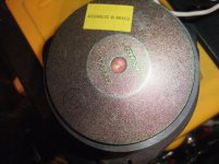
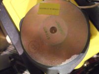
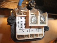
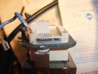
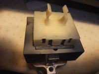
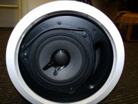
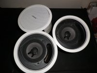
Bose® FreeSpace® Model 32 - how do I get 4-8 Ohms ?

A friend of me get in used condition this satellite speakers (8 pieces model 32) so as two sub-woofers from BOSE's Freespace 3 series II.
Owner's manual is here:
https://assets.bose.com/content/dam...udspeakers/FreeSpaceModel_32/og_fsmodel32.pdf

Page 8-9 explains the fittings/setting taps (configuration), but I don't understand, how get I 4Ω or 8Ω. What is to do on the terminal of the 100 V PA-(ELA-) transformer resp. transmitter (go also to image No 5) ?

Measuring the DC resistance of the chassis driver led to the result of only 800 mΩ (exact same value of the drivers used in BOSE's 901 series).

Thank you very much for an advice.

Attachments

  • Bose Model 32 Driver 0,8 ohms.jpg
    Bose Model 32 Driver 0,8 ohms.jpg
    988.3 KB · Views: 464
  • Bose Model 32 Driver 0,8 ohms-II.jpg
    Bose Model 32 Driver 0,8 ohms-II.jpg
    985.4 KB · Views: 317
  • Bose Model 32 Driver 0,8 ohms-III.jpg
    Bose Model 32 Driver 0,8 ohms-III.jpg
    1 MB · Views: 298
  • Bose Model 32 Driver 0,8 ohms-IV.jpg
    Bose Model 32 Driver 0,8 ohms-IV.jpg
    988.4 KB · Views: 342
  • Bose Model 32 100V transmitter jumper terminal.jpg
    Bose Model 32 100V transmitter jumper terminal.jpg
    983 KB · Views: 352
  • Bose Model 32 100V transmitter jumper terminal-II.jpg
    Bose Model 32 100V transmitter jumper terminal-II.jpg
    746.7 KB · Views: 271
  • Bose Model 32 100V transmitter rear.jpg
    Bose Model 32 100V transmitter rear.jpg
    925.2 KB · Views: 260
  • Bose Model 32 front open.jpg
    Bose Model 32 front open.jpg
    225.5 KB · Views: 240
  • Bose Model 32 front-cover.jpg
    Bose Model 32 front-cover.jpg
    977.1 KB · Views: 239
  • Bose Model 32 front-II.jpg
    Bose Model 32 front-II.jpg
    134.4 KB · Views: 249

What material should I use to mount RCA jacks?

I want to create a panel on which to mount RCA jacks to retrofit the PCB used in my Hafler DH-110. Someone in another thread mentioned Tufnol, but I'm not sure where I would get that in the US.

I looked at "hardboard" sold at Home Depot, but I thought a fiber-based material might not be suitable. I have a crossover out of an old Thiel speaker, and it is mounted on something like hardboard, which is where I got that idea.

The simplest solution would be a brass plate from the hardware store, but then I'd have to take pains to insulate the plugs, or let them all share a ground (can input and out put jacks share a ground?)

Satyrian's Mullard 3 watt amplifier build with 6v6 tubes and issues.

I have just finished building my 3 watt mullard amp with 6v6 tubes instead of el84.
It fires up ok.
One channel did not produce sound at all, but i have found that there is a issue in the wiring from the rca input to the volume pot or from the volume pot to the ef86 tube. So thats gonna be fixed. So i pulled the tubes on that channel for now while i fix the channel that have sound first.
The other channel is playing. Really really low and distorts with just a little turn on the volume pot or if i turn up the power on the input signal. If i turn it really high it just crackles and nousy.i must have wired something wrong or some of the components i have used have some issues of some sort.good tips on where to check first?

  • Locked
Does making distortion measurement of cable make sense?

There are two ways to look at this:

1. Cables are passive devices and therefore linear devices which means they can be categorized as "LTI" or Linear Time Invariant. Therefore they cannot cause distortion. Basically you put in a sinewave, you get out a sinewave no more no less. So most cables would have very low distortion and certainly below human hearing threshold.

2. Or you can say cables are basically an LCR network. Inductors and capacitors are not linear if driven hard enough. The dielectric materials are not linear in the strictest sense. Again if driven hard enough, they can be non-linear. And if cables are non-linear then they can produce distortion like non-linear devices such as transistors.

But regardless, even if cables are not linear in the strictest sense, I would assume if you try to measure distortion of a cable, the level is very low for most cables.

play music from HDD to active speakers controlled by mobile

Hello guys. i don't know the name of this or what device i need to make this happend.

i'v got active spekres. (toslink, coaxial and rca input)
i'v got music library on HDD.
i'v got android box unused ( toslink output, maybe i can use this?)
and i'v got my mobile phone.

so i want to play the music from the HDD to active speakers, i don't know how. maybe raspberry or minipc?

and i want to manage the library and play the music from the hdd with my mobile

max budget - 150€. ideal budget <100€

anyone know how i can do that? is the posible with that budget?

thanks

OB simulator/calculator

Hello guys

I have a plan for build of a OB hybrid WAW(FAST) system.
The woofer part is just OK, but I need some help for the 3,5" full-range TC9FD application. The crossover point is 400Hz 2nd order BW passive and baffle width is 260mm.
How could I make a simulation of the linear excursion related to voltage/power? WinISD or VituixCAD have no option for OB.
Does anybody know some appropriate software?

Many thanks in advance

Any electrical engineers with experience building amplifiers in the NYC/Brooklyn area

I have a potential idea to build an integrated amp, but unfortunately, do not have the skills or knowledge to do so. So, I'm asking if there is anyone who does have these skills/knowledge that live in NYC or Brooklyn, that would maybe want to meet up for a beer (on me) to discuss my idea? I can also let you know what the idea is via PM if you're interested.

Please have experience building out circuits, soldering, knowledge of components, etc.

Improving the LM3x7 regulator circuit

In a post in another thread (http://www.diyaudio.com/forums/showthread.php?postid=334536#post334536), Fred D suggested starting a new thread on ways to improve the performance of three-terminal regulators (a potentially beneficial discussion in my opinion, provided we can keep it on topic):

quote: "Maybe a new thread on design, simulation, and test of high performance three terminal regulators would be worth starting, free and clear of the morass this thread became."

So here it is.

To start the ball rolling, taking the standard datasheet circuit, I would suggest that the resistor in the lower limb of the potential divider that determines the output voltage be replaced with a voltage reference (TL431/???, equal to Vout-1.25V). This should improve ripple/noise rejection and will enable a reduction in the value of the capacitor from ADJ to ground so that the phase margin of the LM3x7 can be maximised. An improved phase margin should reduce the amount of ringing on step loads.

"EMP", a svelte TMM tower...

It's a play off of PMC, with more musically related titling.

Basically, a small format TMM consisting of Seas Al/Mg 27TAC/GB and a pair of Peerless 830991 glass-fiber midbasses in a ~30" tall tower. It's meant to have really low HD for minimal cost, and be a designed update/improvement to the PMC 'Twenty5' design- or at least initially that was the goal. The '25' appears to use the 830991's larger 6.5" sibling singly with the 27TDFC as the tweeter, formerly the 25TAF. We'll see where it comes out in results.

The Titan 27TAC/GB I'm using is a serious upgrade over the previous tweeters, and Joachim Gerhard measured it to have the lowest HD of any similar tweeter with level being at -65dB from 2kHz up. I found this out as an added bonus after I made my previously noted purchase.

The tentative F3 is ~45Hz, and a target sensitivity is ~86dB. The midbasses are of the series that RobSan (Digi) tone-burst tested (830992) to have the lowest HD for the cost, and rivaling that of much more expensive drive units. Using 2 of the drivers will up my sensitivity, further reduce HD at output by halving Xmax requirements, and allow more room pressurization before rolloff. The '25' sounded really good and had extension, but seemed the level at that extension was a bit reduced in output. Using 2 will improve this.

Design being a short tower means optimizing for above the tweeter axis, 10" at the listening position. I designed for this to have an increasing lobe direction instead of being straight forward. I did this with the Nephila project, and it did quite well. The summation in the EMP still aligns well even below axis, so I feel this is a good compromise. The comb-filtering of the woofers in addition to being mainly (above) off-axis contributes to a large hump at about 200Hz I had to filter out. This lends to a more complicated xover in the bass range, but leaves the unpeaky rolloff of the glass fiber cones rather straight forward. It appears that 3rd order works better for the woofers above the tweeter. 3rd on the tweeter electrically was my result, plus a couple other things. Since the tweeter has no FF, I comped the Fs with a full LCR. The 27TAC FR exhibits an ultrasonic breakup at 25-27kHz, which I also have a notch to compensate. I have a switch on this circuit and have measured both with and without the notch engaged to both see and hear the performance differences in measurements and listening. Unfortunately, my measurements showed virtually no change between engaged and open.

Also of note- I obtained 4 of these initially, because the first 2 did not match closely to me. One from the first and one from the second pairs matched without changes. The other 2 were modded and (according to the HD sweeps) improved by better positioning of the internal cotton ball, and adding Ultratouch to the chamber. They also matched well after the adjustments. The 1" ball was inserted into the pole, and the added fill atop that in the chamber and reglued with E6000. Stock, the ball is wedged between the cup's divot and the backplate.

I will agree that from 2-4k, these are very low HD tweeters, and I like their sound a lot. Above there, the HD2 rises with a spike at 4k for the unmodded stock units, while the modded units had a flat HD2 line.

I'll add the graphics later....
Wolf
  • Like
Reactions: Haze Head

Marantz CD73

Hello everyone, sorry for my English, translated by google ... I have a strange problem, after having done the recap of the servo card, when I turn on the player the CD starts to turn, the red laser LED is on steady and the LEDs of the tracks turn on to scan as if the player were in Service mode. All the voltages are present, I know it is a problem with the microcontroller, what do you think? Thanks for your interventions. Paolo

Aspen Headphone Amp

In the spirit of DIY, I've decided to offer a simple headphone amp. Gareth Ingram (aka Bigun) of Ontario will be directing this thread, schematic attached.

And here are the links to subsequent schematics:

Here are links to all the Haksa circuits courtesy of Gaetan, thanks mon ami!!

The amp; The Amp

The same amp with a CCS; CCS

The tone controls with minor corrections, without the volume and balance controls; Tone Controls


The power supply (not final schematic, may change); Power Supply
Cheers,

Hugh

Attachments

  • AspenHP1.gif
    AspenHP1.gif
    13.3 KB · Views: 4,890

Like old Genesis? Get your tix now -

Not sayin how I came to hear a recent show performed halfway around the globe from where I live, but, if you like old Pete and Early Phil Genesis...

Steve Hackett is doing a tour of this material. Maybe last chance in this life to see that almost 50 year old stuff, performed to spec! His tour goes through Europe, Canada and US early next year.

He'll be in Seattle and I'd really like to go, but as a 65 year old man, unsure if it's a good idea to pack myself in with several hundred others in an enclosed space - even with 3 shots 'n all.

Mods just delete this if inappropriate and my apologies if I did anything wrong making this post. Just thought I'd let people know - they do, btw, looking at the seats sold out for a show 5 months away.

DIY Beginner: Horn Speaker Project

Hello,

I will make this intro brief because I suspect I'll miss 99 things and have to update it later anyway 😀

Objective
I want to build some unique loudspeakers - something special to keep. Looks are extremely important, I stand to be murdered by the wife if these things look anything ugly, and given the size I want them to be, which I haven't exactly specified in the wife-approval request, I know they're going to have to be really nice looking.

I will build 2 front speakers. I may also build 2 smaller speakers for the rear, which may be the test-build speakers to begin with.

What I look for
I like big bass for movies, and I like soaring, lofty highs with spacious soundstage with good layer separation and a mildly warm presentation overall for pretty much everything. I do have a high quality headphone system that has treated me nicely for many years, but I have never owned a loudspeaker that could compare with the experience of horns. I have often dreamed of Watt Puppy, BeoLab 5 and similar as icons... but never pulled the trigger for one reason or another.

What and where is it to be used?
In my living room. The room dimensions are 23' high, by about 70' wide by about 50' deep, and boomy.

Speakers that I've heard and really liked
Sadurni Acoustics & Cesaro Beethoven II. Wow. They're frightening, the both of them, and I love the sound.

I've only been to a few shows, so I haven't heard much, but I remembered these two. There was a third, which was also a horn, but I don't know which one it was.

Design Inspiration
Sadurni Acoustics
Cesaro Beethoven II
B&W Nautilus
Aesthesis
Living Vox

Drivers
No preference, but I do think an AMT tweeter is better than even a horn tweeter. I've heard the flagship Piega systems and they're very light and clear.

How many drivers
1 Bass, 1 Mid, 1 Tweeter per speaker.

Perhaps more if justifiable, I don't mind, I'm exploring.

Can I build a speaker as good as the Cesaro, Living Vox, or Nautilus?
I'm willing to try, and get as close as I can, and that will be good enough for me in the end. I can't personally justify paying the price for their speakers, not to detract from those who can. Also, I don't wish to copy their designs, I would like to make something my own, but given the scale of this build and the time it will take, I think I am best to draw as much information I can from their sure steps.

I have the metal and wood work capability and resources to tackle this project at the build level, but I lack, in every sense, the engineering knowledge of speakers; drivers, cross overs, porting, cabinet design, and so forth to do this right.

So, this is the start of the journey, I will likely not touch a piece of wood for some months, but I will begin the process of learning, researching, studying and experimenting.

I've joined here because I learnt long ago that forums are the best resource for support when trying something new or challenging.

Some early questions
I know I haven't really given anything specific for people to critique at this point.... so I will ask some questions, and if you can help with anything at this stage, feel welcome, or just say hi 🙂

1. Are there any existing publicly available designs for something like Cesaro or Nautilus? Or anything even stranger/stand-out?

2. Am I considering the right approach with Fostex/Lowther drivers in a 3-way speaker, or should I be looking to another brand adopting a 4 or 5-way design, and use drivers better tuned at specific frequencies?

Switch mode voltage from power bank, how to filter noise? Use for microphone with amp

Hi! I want to connect my microphone amplifier to a power supply. When I connect it to a 9 V battery I don't get any noise but when I instead connect it to a power bank which have 5V, there is a lot of noise.

Would it be possible to connect some sort of RC filter (low pass) after the power bank in order to filter out the high frequencies?

What cut off frequency will I use, or what values should I use for the resistor and capacitor?

Or is there a better fit for my purpose?

Thank you for your help!

Implementing a true FIFO buffer with low phase noise clock on the Soekris DAM1021 DAC

I start this thread to investigate the opportunity to install a true FIFO buffer on Soekris DAC.

If the sound improves I will provide a interface board and detailed instruction to install the device for those who already owns the DAC.

The true FIFO adds latency so the audio from the DAC will be no longer synchronizable with movies.

Harman Kardon Citation 12 input amplifier

Harman Kardon revised Citation 12 input to use two 43027722 transistors. Original circuit used 8K2 tail resistor for original 43024217 dual transistor, but revised circuit used 12K tail resistor to reduce current trough new input devices.

Does anybody know if 12K resistor was used for get better linearity from new devices, or is it true that this 12K tail resistor with original dual transistor will reduce turn off thump and also DC offset, as it has been suggested?

Best Regards

Kimmo

80mV L ch offset
140mV R ch offset¨

Need help to connect the DAC with BT receiver

Hello all

Sorry for a newbie questions, I have bought this BT receiver together with this PCM1794 dac board.

this is BT receiver
Had453432667742219294b30ab042b7a44.jpg


and this is the dac
HTB1tK11b6fguuRjSszcq6zb7FXax.jpg


I review the I2S connection of both. and found that the SCK pin on the dac I2S input is not present at the BT I2S output.

Could you guide me how to connect them together?

Do they can work together? since. I lately found that the BT receiver is suggested to use with PCM510x chip.

Thank you for every suggestion
Tanwa

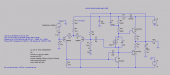
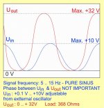
A NON USUAL amplifier PLEASE HELP

Dear Members,


I need to amplify a very low frequency pure sinus signal 5 - 15 Hz sinusoidal
Signal is comming from a signal generator as in attached picture: 1mVpp - 10Vpp, adjustable, ALL POSITIVEI need an output of the signal POSITIVE only,
phase related to input not important.
Load resistance 368 Ohms,

Power Max.: 10W

Attachments

  • amplificator5.jpg
    amplificator5.jpg
    84.4 KB · Views: 430
Projects by fanatics, for fanatics
Get answers and advice for everyone wanting to learn the art of audio.
Join the Community
507,801
Members
7,889,014
Messages

Filter

Forum Statistics

Threads
406,269
Messages
7,889,014
Members
507,801
Latest member
TMCK001