Heathkit audio generator producing bad signal or clipping, where to start?

I have a Heathkit IG-72 Audio Generator. It's been working pretty well for me, albeit the signal calibration was pretty sensitive. Recently it's stopped working all together. I either get a screwed up signal (see attached), or something that's so high voltage it looks like a square wave even at 50V on my scope (Most output frequency selection settings result in the square wave, a few low frequency settings give me the screwed up wave). When I get the square wave, the tungsten bulb goes bright.

I'm looking for suggestions on where to start. I don't want to start pulling and checking parts at random, and nothing *looks* obviously bad. Tapping on the voltage adjustment knob, or some of the parts connected to the tubes causes the waveform to jiggle, for what it's worth.

Happy to provide any additional information you might want to see 🙂

Attachments

  • IMG_3294.jpg
    IMG_3294.jpg
    903.9 KB · Views: 163

Samson SX 1200 repair

Hi

I have the right channel OK et left channel blown.

I changed most transistors (2SC5200 and KSA1943 were short circuited) and diodes on the wrong channel but I still have this problem. On the D101 anode I have 2.5v between diode and ground without input signal and 65 v or more with signal.

I measure this value on the correct channel and it's always 1.1V on D101 anode whatever the input signal level.

I don't understand what is the function of the Q127 and Q137 transistors. I changed them but I replaced the Q127 with a 2SC3200GR, not a BL so the Hfe is different. Do you think it could be the problem ?

Regards

Eric

Attachments

Cheap DIY LM3886 or...?

Hello everyone!


I have been looking into getting a new amplifier to play with. Mostly as a chance to swap my current class D amplifier in my desktop setup as well as using the building/soldering of the amplifier as some learning experience.


My current Class D amp is a TPA3116 with a 5532 Preamp.


I've been thinking about getting a LM3886 kit "on a budget", I have seen many great boards for this chip but I can't really afford them of now.


Doing some searches, Aliexpress does have some fairly interesting (looking...I know little about the 3886) kits, this is one of them:
Placa de amplificador de potencia unisian lm3886, amplificador operacional independente auido op07 ne5534 com protecao para alto falante 68w|Amplificador| - AliExpress


My question is, does anyone have any experience with those cheap kits?

Or, should I use my current budget (about 50 USD) to get another kit or components to build something?

Any recommendation or advice is much welcome, and just in case it serves the purpose, anything around 10 W or even less is good enough, as long as it can handle 8Ohms and have a fairly decent sound quality. Single rail PSUs up to 24V (I have a meanwell one) would be perfect, but I wouldn't mind needing to get a transformer, I should have a 13.5Vx2 laying around.

Help wanted - SET OTL Headphone amp

I've been looking in to building a SET OTL headphone amp and I want to use the tung sol 6SN7 for the voltage gain and Svetlana 6AS7 as power tubes. B+ is 200V right now but this can be adjusted I just don't want to face any huge issues with the 250V rating of the 6AS7's. the goal is to drive a pair of HD660s with ease and maybe even something with a lower impedance in the future.
I'm facing some issues with the simulation (orcad 2019) it seems like the coupling cap in the first stage is blocking pretty much everything I get roughly 5 uV swing after it even if I have a good 10v swing before it (which is still too high for the bias of the second stage).
Do you guys see any horrible misstakes made?
how can I improve it?
Do I need electrolytic coupling caps in the output stage as well or is it safe with only the poly ones?
also am I adding the negative feedback from the output the correct way, how can I increase it?
Lots of questions I'm still learning my ropes around these circuits.

Attachments

  • SETOTL.PNG
    SETOTL.PNG
    27.3 KB · Views: 328

Geddes on Distortion perception

I wanted to start this thread because I find that a lot of people aren't aware of the work that has been done in this area in the last five years or so. Much of this work is my own (our own) but there is also a lot of corroborating research - notably by Alex Voishvillo at JBL among others. I am best equiped to talk about my own so I won't specifically discuss others, but I am aware of it and it virtually all is saying the same thing.

In 2003 my partner and I published two papers on the perception of nonlinear distortion. Much of the results from this work is available here http://gedlee.com/distortion_perception.htm.

Basically through an ellaborate test of some 25 college students we were able to show that THD and IMD are meaningless measurements of distortion as far as perception is concerned. Basically one cannot say that something does or does not sound good based on these measurements. .01% can sound outrageous in some cases and 25% can be inaudible in others. The numbers are meaningless.

This result has been confirmed by several sources and now virtually eveyone in the loudspeaker business is coming to the conclusion that making THD measurements is pointless. Floyd Toole believes that nonlinearties in loudspeakers is irrelavent as evidenced by the fact that his new book contains no discussion of this topic. Lorri Fincham recently remarked at ALMA that THD and IMD were completely meaningless as a judge of sound quality. My own presentation from ALMA (China) last year says the same thing and maybe goes even a bit further.

Basically distortion, as we are used to thinking about it, is completely incorrect. This was further confirmed when we did a study of compression drivers published in JAES. In this study no one of about 30 subjects could hear nonlinear distortion up to the thermal limit of the driver - some 126 dB at the waveguide. This result was surprising and quite controversial, but it is holding firm as quite correct.

There are things that we perceive as distortion-like artifacts, but these are not nonlinearities in the drivers themselves, but are actually nonlinearities in our hearing system. This was brought to like by my partner and I in Oct. 2006 at the AES convention. These diffraction-like artifacts are perceived quite readily by us, but only at higher SPL levels, there are not audible at lower SPLs. These effects are virtually ignored in most loudspeaker designs.

All in all the situation is unfolding quite differently than what has been presumed to be the reality.

Recent studies of mine have clearly shown the human PREFERENCE for distortion of low order or at higher amplitudes. These are viewed subjectively as enriching the sound.

I am putting this topic out so that people can become aware of what is being recognized as the truth about distortion. Its not what we thought it was. Pursuing a loudspeaker design to lower the distortion is a waste of time if its nonlinear distortion that you are trying to lower. It simply doesn't matter.

Using 6.3 v winding for relays power supply

Hello,
i'm doing a metal preamp that uses 12 vdc for heaters. So i used the 12V winding for the heaters with a diode bridge (4x1N4007). It works good.
But i used the 6.3V winding to give 6 vdc to the relays and the leds. I used a bridge that is 80 v 1.5 A and a 6 v voltage regulator (with 2 capacitors) and the bridge burnt after 2 secondes of no load at all, the relays were not connected.

Why?

Thanks

TA-5650 V-Fet rebuild

I recently bought an old TA-5650 amp in very decent condition and am in the process of cleaning and servicing it.
The amp appears to be a letter model, with the changes made in the Dutch service bulletin and with the wire wrap power leads instead of connectors.
I have replaced the suicide diodes and installed the double diode centre ground in the voltage doubler circuit.
Yesterday I measured the V-Fets and noticed that one of the 2SK60s (number 6) was showing a little high on the SD measurement of around 3.5 ohms. Am I looking at a shagged V-fet here ? If so, does anyone know if there is any place to source a 2SK60 with JC-54 grading?

Cheers,
Jon

Attachments

  • 32EF8451-CC99-4E3D-BA20-4F5A05637FF3.jpg
    32EF8451-CC99-4E3D-BA20-4F5A05637FF3.jpg
    1,018.8 KB · Views: 413

3D printed biradial ES-800 horn by Joseph Crowe

I bought the 3D model from Joseph Crowe and now it is being printed. One half finished, second one will be finished in a few hours. My good old Beyma CP385Nds will be measured on this horn. One half uses ca 130 m of PLA filament and with 0.3 mm layer and 20% infill it takes about 15 hours to print. The bottom part on the first piece is slightly warped, but that is no big deal, since the top part is flat for glueing. The second one will be printed most probably with more infill so that I will use one spool for both halves. And it maybe will bend a bit less with more infil. Woden CNC'd would look better, but if I ever have these made, they would be the larger ES-600 for 1.4" driver, I have Beyma 755Nd on my shopping list🙂

Attachments

  • 1E4F5307-175F-4F0A-B844-509BD20D2B88.jpeg
    1E4F5307-175F-4F0A-B844-509BD20D2B88.jpeg
    75.8 KB · Views: 980
  • DFB40CFD-127A-4B88-8A93-956A2012FB3B.jpeg
    DFB40CFD-127A-4B88-8A93-956A2012FB3B.jpeg
    77.5 KB · Views: 949

Soundeasy help!

Hi!

Who here has mastered Soundeasy?

I use Dayton for measuring TS and impedance, I would like to input TS parameters in Soundeasy and start modelling a box. I have heard its a complicated program to learn but I bought it. I have looked into the Music and Design guide v4 but I have a newer version, some things are different and the guide starts with measuring TS parameters, but I would like to insert them manually. I tried but have no plots showing. I really want to learn this program, because it promises the best results but the info on the net is not enough for my brain. Maybe there is a way

I have been using Hornresp and WinISD and seem to understand them quite well, but now I need to model boxes as precisely as possible

A simple bassreflex box with a front port for start would be nice to understand how to model.

A

No Class AB possible

Moin! (Means hello in northern germany)

I try to build an class AB push pull tube amp with KT150.
But it only workes in Class A. If the Power is going higher than 1W, the sinus is collapsing.Any suggestion what can be wrong?

The power source can spend 1.2 A and the actual consumption is ~ 160mA.
The is no disturbance of the gate signals of the KT150.

Greetings Kai

Attachments

Suggestions for a small hybrid 20W amp?

V1 is well underway - that's my personal headphone amp for my mancave.

I'm now looking for a small 20W stereo amp to drive some full range smaller Markaudio speakers. Footprint size, square and 12" corner to corner (realistically 10") to sit in the living room under the TV on an open shelf. Basically this is for the mrs to listen to Adelle in the front room on the CD/Bluray player. If possible the supply in the same box, but option for a small external supply box exists.

I was thinking of a small SRPP with a solid state backend - perhaps a small class D backend fed by a SRPP buffer (the recent thread got me thinking).

Has anyone done any projects like this?

Perhaps something like this: Hybrid Amplifier by Andrea Ciuffoli but scaled down from 100W.

Sanity check for no Compromise 2-way - woofer & CD

Would love for some wiser & more experienced folks to chime in on this project, as I've been going back and forth on driver choices and design decisions as I wait for the SEOS 18 1.4" horns to arrive from Autotech, a slight roadblock at this stage.

This build is intended for moderate listening levels (hi-fi) 90% of the time but needs to be able to withstand PA level territory (115dBA-120dBA) as the multi-purpose space might host the occasional DJ set. A total of 4x 2-way cabinets in a 80ft x 25ft room with 2x Danley TH118 on sub duties.

g1.jpg

My two questions aim at finalizing design choices on a no compromise high-efficiency 2-way with a big (14 or 15"), low-mms woofer with great midrange & break-up behaviour + a 1.4" CD that is a great fit for the SEOS 18-1.4 and it's dispersion characteristics for an xo between around 650-950hz (more on this below)

-System is active (BLU 160, FIR filtered)
-2x Danley TH118 on sub duties
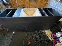
-cabinet volume limitation around 75L-100L (port layout based on Altec 9812)

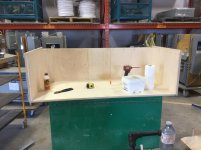
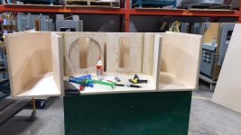
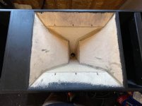
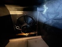
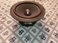
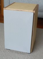
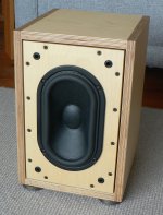
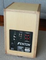
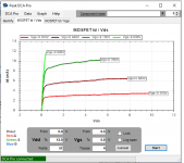
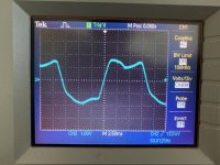
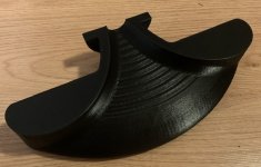
I was originally set on using 4x JBL 2226H I have on hand (and for which I built a test cabinet with good results). But I had a bad surprise when I ran measurements on all 4x units: only 2x have original cones, the other two have been reconed with what appears to be aftermarket cones. Here is the test cabinet and FR/Impedance plots.

g2.pngg3.jpgg4.jpgg5.jpgg6.png

Since the JBL is old tech that clashed with the rest of the components anyway, I went back to the drawing board & set out on a search for modern 15s that fit the bill. But before committing to anything, I want to measure the SEOS 18 1.4. I'm basically hesitant to commit to other aspects of the build before I can fact-check my design decisions with measurements of the horn.

Tell me if I'm over-thinking it, but here's my reasoning:

Since the polar plot of the SEOS 18-1.4 is inexistant online and unavailable from Autotech, here is the plot of the SEOS 18, the closest relative to the SEOS 18-1.4 for which there are polars available. From my interpretation of the polar plot, it seems the dispersion is effectively closer to 70°h x 80°v between 650hz and 900hz?

g7.jpgg8.jpg

I'm concerned that my dispersion measurements of the SEOS 18 1.4 turn out to suggest a higher xo than what I originally had in mind based on the SEOS 18 plots above.

If the pattern control at 750hz is marginally better than in the SEOS 18, could it mean the dispersion no longer matches the 15's narrowing dispersion at 750hz, or would that be a negligible difference? Seems like I could be looking at an ideal xo point closer higher than originally planned.

Alternatively, would you consider this a good setup for the DCX 464, with a 500hz-650hz xo? This would mean I'd have to use the horn below it's pattern control cutoff. The consequences of this seem negligible vs. achieving a directivity match at the crossover point. Thoughts?

If there's a possibility to cross lower by using the DCX 464 instead, it would mean i'm no longer bound to using a mid woofer clean to 3khz and can be looking at more midbass oriented woofers. I'm also unsure of the consequences of crossing this low on that horn, aside from the pattern control loss. Anything else I might be overlooking?

Considering I don't need much output below 70hz from these cabinets as they will be used with 2x TH118s, would you stick with the initial plan that called for a woofer with good midrange performance well into 2Khz territory?

Do any of you see any issue with the reasoning of a capable mid woofer vs. more midbass oriented alternatives? I don't see much benefit from the latter when used with quality subs, aside from the ability to play louder for longer. B&C 15NDL76 can handle the occasional abuse from my experience. What about the Faital 15PR400? Xmech is rather low. It also seems to want a cabinet around 150L (like the Calpamos for instance) I'm wondering if that's as good a candidate as I'm hoping.

Here are my woofer options if ever some of you strongly favour one over another:

If horn dictates xo around 650hz to 900hz:
-Faital 15PR400 (wants more volume than 100L, any succesful builds in less volume?)
-18Sound 15MB1000 (hard to get)
-B&C 15NDL76
-B&C 14NDL76 (could 14" be wise? possibly a better dispersion match)


If xo can be lower (500hz to 650hz):
-Faital 15FH520
-B&C 15NW76
-B&C 14NDL88 (14"...)


Am I making a mistake discarding the DCX464 based on the 800hz cutoff of the horn?

What would be your preferred approach for the compromises presented above?

Starter PA system for jungle/drum and bass

Very beginning:

4 G subs loaded with RCF L18P300

2 Mackie SRM550

Upgrades:
Either addition of 3 Cubo Kick 15 loaded with Kappa Pro 15A

OR

2 G subs become kick bins, drivers from the other 2 G subs are used in 4 Paraflex C2E 1x18"

The G subs are a very simple build with decent output, with 8 of them lined up will be sure to provide the sub and kick to begin with.
The Mackie SRM550 are a bit more budget friendly high output mid top that should last for a decent while, while having good clarity.
Deciding how to upgrade will most likely depend on budget/what the future of the system would become. If it stays more local and smaller, the Cubo Kick will be the go to upgrade (as it stands right now) and if the soundsystem will see bigger venues and bigger events then the paraflex will be eventual upgrade.


Will mostly be used at the start for upto around 200 person gigs outdoors, and upto around 300 indoors, focussed mostly on jungle and drum and bass.


Any feedback on anything within here would be helpful. Recommendations for alternative designs for subs or alternative tops would be appreciated 🙂

JBL Nano K8 vs JBL308PMKII: Whats the difference?

Hi,

JBL Nano K8 vs JBL308PMKII: Same woofer size, same waveguide size, both active crossover biamp systems. Functionally they seem to be identical, whats the difference? I dont get it.

JBL NANO K8 | JBL Professional Loudspeakers
https://www.amazon.com/JBL-Professional-Next-Generation-Powered-308PMKII/dp/B077NHM2K6?th=1


Thanks and Regards,
WonderfulAudio

Sansui AU 9500 loudness

Need a little help , I have a near mint au9500 in bench . Everything is original and fully working but not the loudness.
The original volume pot was replace for a modern blue alps . This has no tap for loudness so the wire from pcb have been isolate .
Now I like to have it again ,. I don’t mind if loudness depend on volume pot position . Just switch loudness .
I have tried with 3 resistor value 3/10/47 K.
First I solder the resistor from tap wire link to the middle of pot . No difference
Then from tap link to ground.... no difference .
I think need two resistor one from input of pot to tap and another from tap to ground .
Someone can help me or maybe already had experience.
Just a little and show schematic part

How to choose plate resistor on 6922 gain stage

Was reading Merlin's HiFi Preamp book, he talks about the golden ratio and 1/3 Imax with 2/3 of B+ (or HT).

Since ra is roughly 3k in a 6922.
(My B+ is 250V):

Ra should be 2xra.. so 6k. Isnt it too low?
Imax then would be 41.6mA.

And center bias would be.. 2/3 of B+ = 167V ; Imax/3 = 13.8 mA.

Is this correct?
How should I choose proper plate resistor?
Thanks.

AD1865 + volume control + TPA6120 on one PCBA for portable

Hello,

I want to make a portable DAC+headphone amp. Powered by mains, but not huge and heavy like my normal DAC with tube output and OTL headphone amp.

On the other hand, I want to get the best out of it what I can.

I stick to the AD1865 in NOS config, and TPA6120 at the end. What is in between is new to me again. Last time I've used opamps was lots of years ago.

I would appreciate if you would look at it and tell me if you have concerns if it works, or, how would you improve it.

Thanks a lot,
JG

View attachment sch.pdf

STK modules

A friend asked me to fix her Toa model KD-1 integrated combo amp. She plays Cello in a local quintet.
This unit has one mic input, four RCA type inputs an amp, and a 12" speaker with a secondary small cone (forgot what hey are called) attached to the same voice coil. TOA had a good rep back in the day,
Anyway, the power amp is bad and it has one of those dreaded (IMO) STK modules which is a complete audio amp in an lage hybrid IC package.
I've only heard how unreliable these modules are. I suspect the run away thermally?
It has the STK 3046V. specifically which doesn't seem to be available.
What's the scoop on these things. There appears to be many variants. Do they all have the same pinout?
Should I attempt replacing with a different variant.?
If I owned it, I'd replace the module with a class D amp I suppose. I'm not willing to put that much time in someone I'm working on for free for though.

WTB/WTS Infinity 2.6 active speakers/parts

I have a pair of Infinity 2.6 active speakers in good condition, except that one BASH amp for a woofer is not working. Am willing to part them out, sell both as-is ($300), or purchase a working speaker or internal amp crossover so that there will be a working pair of these good speakers for someone.
Let me know if you wish to buy or sell parts or complete speakers.
Thanks for having a look.

Wall hanging behind the couch

Our lounge room is our listening room and has a few of the normal problems associated with small rooms that are square.
Room is 4 * 4 and 2.7 high.
I'd like to put something on the wall to help a bit with HF bounce and I need to have some convincing arguments when having the discussion with SWMBO.
I was thinking of a single layer of something very heavy like 40kg felt or double thickness carpet but The Boss may prefer something diaphanous. Is a double layer with the LW net on the front coupled with something more solid closer to the wall more effective?
My beloved is highly resistant to me going back to hanging old woollen blankets.
On that note how effective are floor rugs as wall hangings?
The wall hanging would be about the size of a medium sized rug, say about 1500/1800 * 2700 / 3200mm
No need for it to hang lower than the back of the lounge or the chairs IMO

JFET Buffers - Tektronix vs Pioneer

Hello!

I'd like to build a JFET buffer to be used either as an input buffer for a power amplifier or for S&K filters for electronic crossovers (similarly to the LX Mini crossover by Nelson Pass). I can't decide between two topologies.

On the left, a JFET buffer designed by Arthur J. Metz in the '80s for Tek 'scopes (US Pat # 4,471,319) and modified to use N channel JFETs; on the right the input buffer of the Pioneer A09 Class A amplifier (authour unknown), modified to use available JFETs.

I plan to use LSK170 and LSJ74 JFETs for the input device(s) and J112 and J270 for the cascodes (the only reasonably complementary pair with an available P channel JFET amplifier - not switch - I've found; suggestions for alternative parts are welcome).

I'd like to hear expert opinions about the two topologies (beside the obvious disadvantage of the need for P channel JFETs for the Pioneer). Suggestions for alternative topologies are welcome but the complexity shall not exceed the Tek circuit and part selection shall not exceed the requirements of the Pioneer circuit.

Thank you.


Giorgio

Attachments

  • Input Buffers.jpg
    Input Buffers.jpg
    187.2 KB · Views: 641

PSU Calculation

Hi Guys,

Just looking for some help with the power supply requirements on a LM1875 based amp im trying to plan. Currently my plan is to use a unipolar supply biased. I've come up with the below and i was wondering if I was correct or if i was just confusing myself.

Audio Signal Voltage : 0.775vRMS
Speaker / Load Resistance: 8 ohm
Efficiency Assumption: 50%
Continuous Power: 5w

Am I on the right track in saying to achieve 5w @ 8 ohms with a 50% efficient amplifier i would require a 36v supply which would source just under 1 amp of current to avoid it from clipping?

I also know that the LM1875 needs a closed loop gain of 10x to stay stable, but I can attenuate before the amplifier to reduce in input signal to achieve a power target.

Attachments

  • PSU Requirement.JPG
    PSU Requirement.JPG
    25.6 KB · Views: 243

Any designs for a simple tube-based buffer circuit?

Hello all. I have a bunch of old vacuum tubes and I was wondering if there are any circuits that use simple tubes (preferably AA5 tubes like 12BA6, 12BE6, etc) as a sort of buffer to add tube-like timbres and tones to an input audio signal. I am not an expert when it comes to working with tubes (I generally try to avoid it when possible) so any help is appreciated. Thanks

Buf03 discrete clone?

Has anyone ever tried to make a discrete copy of buf03 or even sim it? The circuit looks very unique to my untrained eyes. Probably lent a single ended sound which is part of why the chip is held in high reputation to this day. And its uniqueness alone could be of great value in this day when theres one too many diamond buffers floating about.

Attached is the most detailed schematic i could find. Id be happy to breadboard it if the missing details could be figured out.

Attachments

  • 20211123_024511.jpg
    20211123_024511.jpg
    130.7 KB · Views: 300

FE138ES-R - Dave, your dream came true...

Howdy y'all.

been searching the japanese sites recently. a simple google for yourself will do the topic justice.

apparently, the FE138ES-R in a 5 inch swan style enclosure is recommended.

start drooling. I hope they make enough to satisfy the global market this time. so put pressure on them.

they will likely not be super expensive. I would estimate them at about a grand usd a pair. or thereabouts.

active X-over

hi guys!

i'd like to bi-amp my 3-way speakers. to do it properly, i need an active crossover. The passive crossover crosses at 300, and 3500 hertz. It is my intention to use an active crossover at 300 hertz, and keep the passive one at 3500 hertz.
does anyone of you have experience with a variable crossover as used in the world of PA? Is it a bad thing that the passive crossover in my speakers is of a 4th- or 3th-order, and that most active crossovers are 1st-order?
any help would be appreciated!

keyser

Any help diagnosing an old Hypex amp? Cutting out on high power.

Hello,
I have a Hypex UCD400ST that is about 12 years old, and I haven't used it in the past couple of years, but pulled it out, and it is having some problems. At low volume it works, but once it gets only slightly loud it cuts out and resets continiously. I put a meter on the VIN, and it doesn't seem to cut out, so I guess it is the amp itself. Any ideas on what I can check? I don't have a scope, but just meters.

Thanks.

Will (this) heatsink sufficiently cooly (this) high-power resistor?

I'm looking at parts to build a dummy load. I am considering using one of these 100W resistors: Acl Ap101 | Ohmite Mfg Co

I identified this heatsink: Sink F R | Ohmite Mfg Co

Based on a figure of 3.5W at 25C.

I have a hard time understanding how to match up parts and heatsinks, which is why I'm posting here. If I'm off track, could someone people explain the process for selecting a heatsink for a given part? When I google, I find mostly stuff about designing custom heatsinks.

How to Screw up The SP-10: Help needed...

Actually the title may be misleading - I don't need help screwing up my SP-10, I've done that myself.

I bought an SP10 that didn't have a PSU. I built a PSU according to the design by MP Barney. It's a clever design that starts the 32.5VDC a bit later than the 5V owing to a larger capacitor on the 32V regulator. I've built one of these previously and it worked like a charm.

HOWEVER, I'm an idiot: I connected the 32.5V supply to the 5V connector on the table, and vice versa. I corrected it but the table won't run. I suspect I've screwed up the logic circuit by supplying it with 32V instead of 5V.

I don't have the slightest idea where to start troubleshooting. Any suggestions will be appreciated.

EVEN BETTER would be someone who would do the repair for me. Of course I'd pay the going rate for this work. If you're willing to tackle this, please drop me a PM or email at whirsch@indy.rr.com

Thank you.

Understanding Op-Amp LPF in DAC

I am refreshing an ADCOM GDA-600 DAC as a learning experience and trying to understand some of the LPF used here.

This DAC uses dual channel op-amps per channel. To my understanding, each opamp does both I/V and filtering.

I've attached the relevant section of the schematic.

A few questions:
1) Is it correct that this is a "second order LPF" ?

2) There is an LC filter on the output. Is this actually needed given that we already have active filtering?

3) Can the circuit be optimized here? The cap values here seem to be non-standard based on Digikey and Mouser inventory. I've also read somewhere that the resistor value should be between 10K-100K while 1.21K is used here.

Thanks!

P.S I will be replacing the stock op-amps with OPA2132 if that matters

Attachments

  • Untitled 2.png
    Untitled 2.png
    189 KB · Views: 941

Aleph L gain / switchless board

Hi All.

Aleph L first revision without switches is giving too much gain. Hardly possible to listen, its playing with original pair of Aleph 0 monos. Even on the second pot position it's almost too loud. Friend of mine bought it used from Japan. Surprisingly no dip switches onboard. (see pictures).

Any schematic available for this particular revision? Nominal values are of the most interest. Board picture is attached.

497f8156-86f3-4fb4-b871-8feb5cd26b62.jpeg

8c81e0df-0cae-4066-aeac-263385536b70.jpeg

0aea7cfa-9369-4c49-ae90-a63f530a17ce.jpeg

crest audio 4001 profesional power amplifier help biasing help

hi i bought a damaged crest 4001 amplifier

998273d1637121923-crest-audio-4001-profesional-poer-amplifier-help-biasing-help-crest4001-jpg


im new to repairing amps i have repaired already half a dozen

but this is my first profesional amp

so i already changed the damaged nec 2sb600/2sd555 https://www.diyaudio.com/forums/attachments/solid-state/998278d1637121923-crest-audio-4001-profesional-poer-amplifier-help-biasing-help-datasheet-2sb600-2sd555-nec-pdf outputs transistors for on-semi mj21195/mj21196 https://www.diyaudio.com/forums/attachments/solid-state/998279d1637121923-crest-audio-4001-profesional-poer-amplifier-help-biasing-help-datasheet-mj21195_on-pdf
changed all the capacitors, some damaged resistors, diodes, the damaged toshiba drivers 2sa10006/2sc2336 https://www.diyaudio.com/forums/attachments/solid-state/998280d1637121923-crest-audio-4001-profesional-poer-amplifier-help-biasing-help-datasheet-2sa1006-1006a-2sc2336-2336a-2336b-pdf for on-semi mje15032/mje15033 https://www.diyaudio.com/forums/attachments/solid-state/998281d1637121923-crest-audio-4001-profesional-poer-amplifier-help-biasing-help-datasheet-mje15032-pdf and a damaged mje340https://www.diyaudio.com/forums/attachments/solid-state/998282d1637121923-crest-audio-4001-profesional-poer-amplifier-help-biasing-help-datasheet-mje340-pdf for a new of the same

the amp is turning on the 3 relays click and i have output the thing is the biasing preset is turn all the way down its a 250ohm preset its my first to-3 transistor amp i fix and i cant place the probes easily as a to-222 transistor because of its design and i need help so where i can place the probes to calibrate bias and if i need to put a higer ohm preset

Attachments

Sockets for Capsules

A boring question but needed---

I find soldering a pair of wires to tiny microphone capsules to be a daunting task. I tried both lead and silver and while I am succeeding it is slow and I overheated a few capsules.
Short of cutting PCB boards to mount these does anyone know if there exists, a socket to receive the common lead spacings of small capsules?

Thanks
Fritz

B2 MA 6000.1

I received this amp for repair.. Obviously everything is OK. It started for a few seconds, than in protect. Checked the audio banks, one works good, the other has problems to build up waveforms. I don't now this drive board. Is there also irs21844s inside? Mosfets measures all OK. The output from the drive board is buffered.

Attachments

  • IMG_20211109_192230.jpg
    IMG_20211109_192230.jpg
    760.3 KB · Views: 223
  • IMG_20211109_192225.jpg
    IMG_20211109_192225.jpg
    982 KB · Views: 198
  • IMG_20211109_192301.jpg
    IMG_20211109_192301.jpg
    680.5 KB · Views: 189

AVR voltage regulator - what to look for

My AC main voltage seems to have crept up quite a bit. We used to get ~225V AC a few years back, and now it is around 240V-245V AC.:scratch1:

Given the situation, I am thinking of installing an AVR (Automatic Voltage Regulator).

There are various types - which ones are good for audio?

I have posted on the solid state forum as I intend to run solid state gear on the AVR regulated mains. If the moderators think this thread should be part of another sub-forum, please move it there.

FS Fostex T90A and Fostex R80B

Hi, for sale 2 Fostex T90A. With very little use (50 hours approximately) and Attenuator (L-Pad) Fostex R80B (two units). Gift 2 capacitors of 0.47Uf necessary for connection. I send photos to those interested.

Shipping only to EU, shipping costs borne by the buyer. Price for everything 500 euros non-negotiable, if I sell separately 450 euros the couple of Fostex and 60 euros the couple of R80B.

Best regards

DIY PA system

Hi everyone. I’ve been building a high end PA system in the past few weeks. Ultimately it’s more or less a copy of the pm90 but using bigger driver. Instead of the 12 inch woofer I’m using 2 15 inch B&c 15nw76. I’ve also decided to use a bms 4599he coupled with 4 ciare ct440 super tweeters. I’m still waiting on my bms 4599he as it’s being build, but almost everything is done except for a few touches. I have been contemplating a few ways on how to mount the 4 super tweeters. Given the limited space I have left, I was thinking of just mounting them one on top of they other. The only problem I’m running into is, coverage. Ciare has not shown it’s of axis response nor its coverage pattern. So coverage might be limited if it’s all on the same horizontal axis. On a side note, I’ve built a 90x40 horn for the bms 4599he. So ultimately I would want the coverage pattern on the tweeter to be quite similar. Any suggestions? Additionally, I’m not exactly sure of the built quality of my horn for the bms4599he. The horn sensitivity is obviously a big concern as it’s meant for pro applications. It also need to be able to play at least down to 650hz where it will be crossing with the 15inch woofer. Any suggestions would be much appreciated. Thx

Attachments

  • 4B724502-F179-4792-828B-CF90265627BD.jpg
    4B724502-F179-4792-828B-CF90265627BD.jpg
    752.9 KB · Views: 442
  • 46E01991-3410-48BF-816E-BA3BCD2EB391.jpeg
    46E01991-3410-48BF-816E-BA3BCD2EB391.jpeg
    269.4 KB · Views: 386
  • B5D96CE6-AD2A-4EB0-B321-B23A77131AEF.jpg
    B5D96CE6-AD2A-4EB0-B321-B23A77131AEF.jpg
    1,010 KB · Views: 407
  • 4667B27A-112D-403A-8039-DDD19888438A.jpg
    4667B27A-112D-403A-8039-DDD19888438A.jpg
    656.8 KB · Views: 384
  • 6BB6950B-734D-46CC-907D-A5BEFD8C18DA.jpg
    6BB6950B-734D-46CC-907D-A5BEFD8C18DA.jpg
    989.7 KB · Views: 373
  • 6B73B348-8D4E-4F5D-B7EB-FAB1C41AEA73.jpg
    6B73B348-8D4E-4F5D-B7EB-FAB1C41AEA73.jpg
    904.6 KB · Views: 247

What DAC?

Hello,

I've built a player (or several before 🙂 with RPI+moOde >> I2S FIFO >> serial convert >> AD1865 >> I/V trafo >> ECC82. That is my main DAC, but now I need one for headphone music listening. I would use an XMOS / Amanero USB >> I2S board than an I2S DAC.

If I like AD1865 the most, what modern DAC would I like now? AK or ES ? Which version?

As far as DAC chip, which is the best nowadays for mainly acoustic music?

I have a Chinese AK4497 board what I do not like. I guess it is the opamp output, but It is rather harsh. I do not like to wash away details, but for me, quality comes when it sounds pleasant and detailing in the same time. Of course, it could be that the DAC chip is just a copy also, so I do not judge based on this, but I need help which DAC should I go with?

Thanks a lot!
JG

What drivers to replace FE206E?

Hi All,

About 15 years ago my father and I built a pair of cabinets using FE206E drivers. I'm almost certain these are the design plans, even though the driver listed is FE206EN.

https://www.fostexinternational.com/docs/speaker_components/pdf/FE206En.pdf

The drivers have seen better days so I'd like to replace them.

Should I replace them with the Foster FE206E, or are there better options now?

Advice on amplifier choice is welcome as well-I've always wanted to build a tube amp for them but haven't gotten around to it...yet!

Fostex FE126EN Vs FE126NV drivers ( Pictures ).

Good evening everyone. I thought I would share pictures between the two Fostex Fe EN vs the Fe NV driver’s. I have not heard the new Fostex FE126NV drivers next to the FE126EN drivers which are one of my favorites. So I will be doing a project with the New NV drivers soon. So here is my take on each driver Just looking at them both side by side.

Fostex FE126EN Driver’s.
1. Has a bigger magnet.
2. The cone is almost very light and almost see through.
3. Heavier.
4. Nice live sounding.
5. You get more Info on the drivers Mechanical specs and small parameters.
6. Has been around a while.

Fostex FE126NV driver’s.
1. Cleaner wire hiding and no white dots on the cone from soldering.
2. The magnet is not so big and is more rounded even.
3. Gold plated terminal’s and are spaced out a little more from each other.
4. Frame is more of a glossy black and not a coated black finish.
5. The cone looks cleaner around the edges and the middle dust cap.
6. The cone looks more stiffer and has sparkling on the cone? Fairly dust 😀
7. Shipping with a plastic speaker cone protector.


Things I don’t care for in each driver.
1.Still has a steal frame and can cause a problem if you don’t dampen it some how.
2. Magnet is either to big or small nothing In the middle or a different type of magnet material.
3. NV has very little info on published driver Info like T.S.
4.FE has a sloppy look to around the dust cap and outer edge of the cloth sound.
5. Charges a lot for the drivers.


This is all I can think of. Again I will be working on a project soon with the new drivers and I will post pictures and give my honest opinion. Cheers Jeff

Attachments

  • CFE5BD07-DCF4-4B7A-B61C-7FBE34A3B415.jpg
    CFE5BD07-DCF4-4B7A-B61C-7FBE34A3B415.jpg
    1,020.5 KB · Views: 365
  • D8E34F54-4AC7-4475-BA64-D9E954CF219C.jpg
    D8E34F54-4AC7-4475-BA64-D9E954CF219C.jpg
    1 MB · Views: 460
  • C827DF51-2034-4C87-9245-92B4D7D7E0C4.jpg
    C827DF51-2034-4C87-9245-92B4D7D7E0C4.jpg
    1,017.3 KB · Views: 607
  • 68418127-FD87-49BA-B45A-DEE5082D1E8D.jpg
    68418127-FD87-49BA-B45A-DEE5082D1E8D.jpg
    1,020.5 KB · Views: 489
  • 71855B37-5C82-4C9B-947A-26CF1CCA5F70.jpg
    71855B37-5C82-4C9B-947A-26CF1CCA5F70.jpg
    1,013 KB · Views: 403
  • E36D52C4-6A77-4390-89CC-C29D794E0EA0.jpg
    E36D52C4-6A77-4390-89CC-C29D794E0EA0.jpg
    1,005.5 KB · Views: 222
  • B9C65B7E-1151-44A9-9013-8412C46B8101.jpg
    B9C65B7E-1151-44A9-9013-8412C46B8101.jpg
    901.3 KB · Views: 232
  • 80BF2929-03EF-48E0-A5CD-46D9C5F1550B.jpg
    80BF2929-03EF-48E0-A5CD-46D9C5F1550B.jpg
    985.9 KB · Views: 303

Hypex SMPS1200A100 Issue

I have amp with Hypex Soft start and Hypex SMPS1200A100 psu. Amp is about 1 month old. Amp was in old box. Yesterday I transferred everything in to nice new Modushop box. When all done, I did a power up check before putting the top cover on the box. All was good. Cover on to box.

So, this morning I'm all excited about the amp in the new box and everything all nice, neat and tidy inside and outside the box. So what happens .........amp does not turn on.

Off goes the cover, turn on amp and I see the Power LED's on the just flash on and off. So something not working right.

Voltage checks show soft start is good. Hypex psu voltage is not good, at +7V and -1.2mV for rail voltages.

SO, is there something simple and fixable on the psu?
Or is the psu stuffed?

I'm just throwing this out there in case this has happened to someone else and perhaps there is some easy answer other than "Get a new one".

F.S. Yamaha DACs DA2X and DA202

DA2X - 220V version
DA202 - 100V version
No repair and no modification before. Original working set.

Please offer me and work out a total including shipping method and cost.

Regards, Spencer

Attachments

  • IMG_4321.jpg
    IMG_4321.jpg
    538.7 KB · Views: 150
  • IMG_4322.jpg
    IMG_4322.jpg
    655.8 KB · Views: 138
  • IMG_4324.jpg
    IMG_4324.jpg
    595.4 KB · Views: 131
  • IMG_4325.jpg
    IMG_4325.jpg
    620.2 KB · Views: 139
  • IMG_4329.jpg
    IMG_4329.jpg
    496 KB · Views: 142
  • IMG_4330.jpg
    IMG_4330.jpg
    403.1 KB · Views: 85
  • IMG_4327.jpg
    IMG_4327.jpg
    639.9 KB · Views: 77
  • IMG_4328.jpg
    IMG_4328.jpg
    669.5 KB · Views: 78

FS: Seas Nextel W18NX001 unit (1 piece)

I have for sale one (1+ 1) Seas Nextel W18NX001 unit. Unit was lightly used for few years and it is in perfect mechanical and electrical shape. The metal plug is nickel chrome polished (new versions has a bit different finish). Original packing included.


Price is 90 EUR + post costs. Payment via PP.

Attachments

  • img_20210215_193353 (1).jpg
    img_20210215_193353 (1).jpg
    391.7 KB · Views: 380

Yamaha A-1 idle current issue

Hello, any Yamaha A-1 DC coupled specialists out there?


This amp is ‘working’ but Idle Current won’t adjust at all with newly installed Bourns trimpots and is at 1000mV on one channel, 0 mV on the other!

So far, I’ve:
replaced all OT’s with MJ21193/4G
replaced four 330ohm resistors at R 101, 102, 103, 104 with https://uk.farnell.com/multicomp/mf12-330r/res-330r-1-125mw-axial-metal-film/dp/9343032
replaced two fusistors at FR 101, 102 with https://uk.farnell.com/koa-speer-el...-film/dp/3541480?CMP=e-email-sys-orderack-GLB
Are the above replacements all correct?

A hum is present.

Readings:
-DC is 35 V and stable
-Offset DC is 0 mV and ranges +/- 5mV.

DMM on the Electrolytic Cap Board:

Negative lead on TP1
Positive lead on TP 3
Climbs steadily up and down between-500mV to -1060mV


Negative lead on TP2
Positive lead on TP4
Settles on exactly 0mV !

Turning up the volume control (whether ‘Aux button’ with signal and sound is selected, or ‘Tuner button’ with no signal, result is the same) reduces TP1 to TP3 reading closer towards zero mV by about 50%..

The sound through the speakers has some kind of ‘resonance’ running through it, hard to describe but it doesn’t sound right.

Switching from Aux to Tuner (with no source connected) and turning up the volume produces a hum through the speakers.

Any suggestions?

PCM63P-K / PMD100 / CS8412 pulled from parasound

Hi,


I pulled the chips from a parasound D/AC-1600HD


DAC:
BB PCM63P-K 20-Bit DAC USA | eBay


PMD100:
HDCD PMD100 Digital Filter Integrated Circuit | eBay


CS8412:
Qty: 1 CS8412-CP Digital Audio Interface 28 pin | eBay


shipping will be cheap first class, if they are up on ebay I can sell them there if you wish, or privately on here. Let me know if pricing is about right or not and feel free to make offers, thanks.


Dave

When is a Ne555 not a NE555 ?

Been working on a new project.
I needed a astable oscillator that would drive a relay.
Found the NE555 will drive 200mA so seemed ideal.
Got the pcb made and built up.
It has a trimmer to set oscillation speed from 15 seconds to 2 minutes.

Tested it and getting 6 seconds on and 24 seconds off !
Pretty useless.
Investigated the circuit for mistakes shorts etc and seems fine.
The circuit I used was ripped from the interweb and appeared a few times so should be tried and tested.

So scoped the circuit and found the output when driving relay is only going down to 1.5 volts. I use the output through a resistor to charge and discharge the timing cap.
So when output goes high timing is correct but because output low is only going down to 1.5 the delay is shortened greatly.

The spec for the 555 suggested 0.5 volts output for 100mA but my relay is only 30mA so should be well in spec.
But not so.

So either need a better ne555 or a driver transistor for the relay.
Will try a different ne555 first before binning the pcb's.

The pcb's were only £2 from jlcpcb and were bought in with a few other pcb's so no big problem.

Free: Subwoofer SB15SFCR39-8 (Newcastle AU)

Free subwoofer using a SB15SFCR39-8 and Fenton plate amp. Has a nice tonal quality and suitable for a computer or a small room. More of a woofer than a sub but goes low enough for music and most movies.

Vb=16 litre sealed, F3=56hz, F6=45Hz, F10=36Hz, 256W x 380H x 273D, 18mm birch ply with removable front baffle.

Pulled the amp from a Fenton SHFS08B sub and has plenty of power to drive the woofer which is rated at 80W. Has gain, xo freq, phase switch with the gain coming in rapidly and the pic shows where I had the knob.

Pickup only in the Newcastle NSW area.

Attachments

  • Sub_sb15_a.jpg
    Sub_sb15_a.jpg
    306.7 KB · Views: 123
  • Sub_sb15_b.jpg
    Sub_sb15_b.jpg
    249 KB · Views: 139
  • Sub_sb15_c.jpg
    Sub_sb15_c.jpg
    252.3 KB · Views: 121

Question about Impedance

This question comes from a place of ignorance and oversimplified logic. Feel free to be as condescending as you wish in your answers.

I was involved in a discussion and using my home system as 'typical'. My main speakers are good down to 50hz. Subsequently, I only need my new subs to respond between 35Hz and 50Hz. For argument's sake let's tune the ports to 42.5Hz. If impedance is highest at the port tuning frequency e.g 32 ohms and does not fall below 12 ohms within the specified does this mean the cabinet is 12 ohms regardless of the nominal resistance of the driver?

R-Core Crash Course

My current project is a Chinese pre-amplifier named after Mr. Curl's JC-2 and I decided to use an R-Core transformer.. From what I have read in other threads, the design is modeled after the JC-2 Actual but not the same so I call it the C-2. I received the transformer yesterday and was immediately confused by all the wires sticking out of the thing. My assumption was that primary leads would come out one end and secondaries would come out of the other. It's labeled as such but I'll check first. One reason I chose this particular R-Core is that it can provide two 18V-0.5A outputs and three 9V-.3A outputs. This can cover a lot of different applications.

Things I knew going in:
I would need a transformer
I heard that R-Core and Toroidal transformers create less "noise" than EI transformers.

Things I didn't know:
Any data pertaining to the C-2 like voltage requirements, line-in requirements etc.
R-Core transformers are built with the primary on one side and secondary on the other
One of the leads on the primary side is for a "shield", is this for shielded cable/wires or chassis ground?
There are two primary windings, can anyone explain the factors that would dictate when both are used? I assume I should use the primary that includes the "SCN" or "shield" lead.
Didn't know then or now, do I need some kind of power supply regulator?

Schematic and photos to follow

Tandberg 300 cassette deck a brief loud hum on Play

Hello friends,

I have a Tandberg TCD 300 Cassette deck. It outputs a brief (~1 second) loud hum upon pressing the Play button and it continues to play normal from then onwards. It happens on every Play click. It doesn't do if I press Pause and un-pause it. It also doesn't do if I press and hold Stop button for the first second while pressing the Play button.

Attached recorded sound for your reference.

Tested all Caps and they are all looking good and have low ESR
Cleaned all the switches multiple times. Cleaned the head and demagnetized also

I saw an exact same issue reported on tapeheads.net but not sure what was the solution. Posted this on tapeheads on the same thread also but haven't received any response yet

Attachments

  • New Recording 881.mp4
    239.7 KB

Circlomenen, can we locate 8th order qw as a function of the speed of sound?

Speed of lihggg :299792458kms. Or 29, 979.2458 in one second instead of the 1000. 500 to earth makes the actual distance to earth 1496. So if we say 30 we mean 29.979 etc. etc.

And if we say 75 we mean 74948 whatever same goes for the other numbers 20 249…


So , 7.5 , 15,22.5, 30. And established four part series on speed of light.


speed of light ,halfway to earth and earth then right on top of Mars and then right back to us.

If there’s a pendulum fulcrum point at the driver set an a line they pull it back to 30 and let it swing to 30 again in one second we have a seSequence of 30 and so then at 90 we are effectively in the center of pressure phase I try to position it goes to the closest wall then back across the driver again and then two more 30s to90.

Repeat that four times and have her do the opposite from the other side it only 90. you have 360 total. .

That you have 13 parts of the sequence sink perfectly for some reason that creates a complete cancellation of sound at 860 hurts and it repeats at that interval at 860 over and over and over again forever. Last seen before exceeding 20,000 at 19780 Hertz. And in between at 12,24,36,(48 , 96,192) it has another ripple like to fournier transform does.

If you hold the button down in your mouth and watch the numbers as they fly through -990 DB at those 860 dumps between lesser rolls, begin to observe the sensation not unlike sitting on the surfboard waiting for the perfect way to come in but feeling all of them that role underneath you or over you while looking for the perfect one which inevitably seems to come at a certain number that is an automatic. ?

We can take all of that and place it into the series path. Using the same 30 where are using 120 and two40 and 360.


Get the same results so awkward and strange yet seemingly perfectly aligned cancellation at 860 intervals.

And with the CSA chosen is a two-part layout for each the folded initial skinny path and the wider final resonator At 4 to 1 or 5 to 1 very delicious response emerges one that looks almost identical to the parallel which would merely be the same but taking that 5 to 1 Ratio and splitting it one more time, Sharing it with the short 90 cm parallel in that case


.Oh you’re a little bit more keen on things outside of acoustics and numbers did engage other elements of physics maybe even knows on the circle if that’s what you looked at it in the perspective of. Whatever this is this is also then representing the locations of planets in the solar system and a whole bunch of other things and that’s all based on the 860 because what that actually is is the second to the day the diameter of the sun the diameter of Jupiter and the location of Jupiter using miles or millions of kilometers or units of time on earth and also it shows the expansion rate because he’s no longer 1440As in minutes on earth or the location where Saturn would be hypothetically it’s 14620 Which is the same amount of days in the leap year of four years as degrees around the sun or not 360 but the same number applies here as a result 05238052380523805238 is the speed of light at a parallax angle which defines location of a great many things including the parsec light year and the big bang distance of visible light at that distance etc. etc. we arrive at all kinds of amazing things but in this case we’re also using that the subwoofer and look at what happens?? Which is the same amount of days in the leap year of four years as degrees around the sun or not 360 but the same number applies here as a result 05238052380523805238 is the speed of light at a parallax angle which defines location of a great many things including the parsec light year and the big bang distance of visible light at that distance etc. etc. we arrive at all kinds of amazing things but in this case we’re also using that the subwoofer and look at what happens happens???

So I build it with 212s not the best not the worst decent no doubt and it’s a monster and I build it again using the parallel version only have one more driver driver for that at the time but it to has that wicked signature to the sound which creates the upper mid subwoofer region a very violent and brutal whip like attack when you really turned over and let it move some air whatever the hell is going on in their there He’s no longer awkwardly weird creating things that formerly stirred up ringing and vibrations and drug that was very messy though inconsistent and when it would show up and we’re including which seem to be periodic areas of limited sound abbreviate sound attenuation sound or partial deconstructive interference due to folding?

We all become is so much smoother and so much more on point if you’re using the speed of light reference to do this and more and more that makes sense deeper deeper look into how and why is this cancellation of -990 occurring in the simulation who is that represent why is the entire upper band with strip naked and just left with the skeleton when otherwise it’s really looks like chaos and massive thick heavy hashmarks. We all become is so much smoother and so much more on point if you’re using the speed of light reference to do this and more and more that makes sense deeper deeper look into how and why is this cancellation of -990 occurring in the simulation who is that represent why is the entire upper band with strip Bare bonesnaked and just left with the skeleton when otherwise it’s really looks like chaos and massive thick heavy hashmarks.

I’m not sure but the pattern of this in heels if you write down all those numbers and the cancellation parts of the peaks is a sequence in that sequence goes on to me and told amounts of information in both directions past zero as well zero which is 180° out of phase of the fundamental which starts to make a lot of sense how or why you could completely go below zero in another way of thinking or another dimension or another existence so speak simply one that we are not aware of anything that we are not able to sense or understand or ever could for the reasons shown in And the layout is soSimple and it Can be extended in 30 cm increments and still provide that unique result of the -990 DB repeatedly being shown at the 860 Hz intervals.


Look at numbers on the circle in radians or degrees or centimeters of circumference they represent a bunch of weird things in many ways 15° or . 2618 we’re half of it at 1309 7.5°. This is all inside a room in the pyramid which is a perfect rectangle that describe a perfect circle. Kind a like a roar can be and still can use these same numbers to break it down?

240° on a circle is 4.188888 that is the volume of a sphere equation when radius equals one if you make a roar 360° (As cm not degrees ) And label every 15° and drop drivers on 30 and 22.5 as you may have to to satisfy the details of the supply room for the exit on the skinny path into the large I need two drivers a post from each other just to start simplifying these things and to allow the offset to exist because it would seem that that Pendulem swing set up a synchronicity that ends or begins or whatever at 360. Or whatever and every single thing including exit that must be at a 90° or 180 whatever it takes to supply a standing wave and a propagating with filtering fact or construct to do things that don’t make it through but are close in size to the oncoming and outgoing when it does in the bigger picture what is happening so rapidly in sound going through there because it changes the music etc.? I don’t know but what you see in numbers in the solar system or another things when given the chance and explain to the same in that way they start revealing the same exact numbers in phase at7.5 or 15 or 22.5 or 30 increments of 45/60/75/90/205/120….. degrees? frequency and millions of kms or millions of miles become centimeters In two seconds just like what happens in late to earth or past and back to it as if it were to visit Mars real quick? After all the distance between earth and mars is 1 to 1.152 astronomical units. And so the angle of 30° which is 0.5238095238 when used in both the subwoofer and when used from the center of the sun outward defines all of these things and if you look 1738 as a hypotenuse in a short leg of 864 please location of earth on the long leg of a right triangle which acute angle uses the speed of light is 29.9792458 produces. And so the angle of 30° which is 0.5238095238 when used in both the subwoofer and when used from the center of the sun outward defines all of these things and if you look 1738 as a hypotenuse in a short leg of 864 please location of earth on the long leg of a right triangle which acute angle uses the speed of light is 29.9792458 produces.

That seems to be the recipe for one hell of a roller or a parallel version or texting me that number shows up in an offset driver transmission line attached exit it’s inconsequential but the driver position will be 104.76 cm in 300 cm, and scene in our response that will be the exact location we’re perfectly filling the void is that for the odd harmonic of the speed of light ??

Attachments

  • 5B542B4E-E681-4EFE-B7F3-11B03FE98364.jpeg
    5B542B4E-E681-4EFE-B7F3-11B03FE98364.jpeg
    565.5 KB · Views: 113

Hypex Soft Start

I have a Hypex soft start and Hypex smps. I want to turn the soft start on/off with a push button LED switch. I want the LED to be on when on and off when off. I have wired up a 1NO1NC pushbutton switch with C and NO to SW and + and - to the LED and put the jumper to the push button ON setting. The softstart and amp turn on and off with the button, but the LED ring stays ON all the time.
How can I wire this so that the LED ring goes off when the amp is turned off?
Is this possible with this switch?

I only turn the amp off overnight and see no reason to have the LED on all night.

what driver for tapped horn?

Hi,
I have an old driver lying around and I wanted to a build tapped horn subwoofer. How can I know if the driver is totally unsuitable according to its TSP?
Thanks!


edit:
Sorry, I didn't look enough, here is what I found at least.
It seems cutoff frequency should be lower than Fs of the driver. A high BL can help move the cutoff higher while preserving flat response. A low Qts means the driver has to be near the end of the horn, mid values are good.

How do I avoid ordering resistors packaged like this in the future?

I just started on the power supply board for my Aleph J build, and these are the resistors that showed up (for the LEDs). The ones on the BOM were out of stock, and these were equivalents. The main issue is the 'coating' (not sure what it's called) goes way down one lead, and goes so far down it goes through the hole on the PCB. I am sure I could make it work (I could stand them up, but would rather not).

Question is, how can I avoid ordering resistors packaged like this in the future? I want them flat/straight as normal. I knew they were cut tape, but was expecting them flat, not like this. Does 'Reel' under packaging have a significance? Thanks!

Here is the link to the specific part I ordered: CFS1/4CVTR103J KOA Speer | Mouser

What I got:

i-KF7SCqH-X2.jpg
Projects by fanatics, for fanatics
Get answers and advice for everyone wanting to learn the art of audio.
Join the Community
507,783
Members
7,888,303
Messages

Filter

Forum Statistics

Threads
406,233
Messages
7,888,303
Members
507,783
Latest member
ys.zhu