Moin! (Means hello in northern germany)
I try to build an class AB push pull tube amp with KT150.
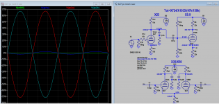
But it only workes in Class A. If the Power is going higher than 1W, the sinus is collapsing.Any suggestion what can be wrong?
The power source can spend 1.2 A and the actual consumption is ~ 160mA.
The is no disturbance of the gate signals of the KT150.
Greetings Kai
I try to build an class AB push pull tube amp with KT150.
But it only workes in Class A. If the Power is going higher than 1W, the sinus is collapsing.Any suggestion what can be wrong?
The power source can spend 1.2 A and the actual consumption is ~ 160mA.
The is no disturbance of the gate signals of the KT150.
Greetings Kai
Attachments
It looks like you're using a constant current source to bias the output stage and it simply runs out of current?
Yes, check the voltage across R19. If it varies with the input, you are out of the constant current range.
Make sure that you have enough heat sink for the mosfet if you increase the current.
Make sure that you have enough heat sink for the mosfet if you increase the current.
Last edited:
R19=17R generates 128mA fix current.
2x78mA= 156mA.
Supertex dn2540 CCS Rset trimmer value
For proper operation DN2540 as CCS requires at least 25-30V V(DS).
2x78mA= 156mA.
Supertex dn2540 CCS Rset trimmer value
For proper operation DN2540 as CCS requires at least 25-30V V(DS).
I think your driver doesn’t give enough juice. KT150’s need a lot of driving power. How is the waveform at the output of your driver stage at different power levels?
Regards, Gerrit
Regards, Gerrit
As soon as one output tube leaves class A it is cut off, current drops to zero.
Which means that the other tube gets all the current from the CCS, 150mA.
To enter into class B however it had to increase its current beyond that, but it can' t because what your CCS allows is all it can get. Full stop.
Which means that the other tube gets all the current from the CCS, 150mA.
To enter into class B however it had to increase its current beyond that, but it can' t because what your CCS allows is all it can get. Full stop.
The 75mA CCS is for output tube idle current, which is DC and AC, limited to 75mA, a few watts is all you can get. You therefore need a bypass capacitor for CCS to allow more (all) AC current that is required for higher output.
Another way . . .
Start with Matched KT150 tubes.
Find the self bias voltage, Vb, that is required to get 75mA cathode current for each tube.
Then, Vb / 0.075A = Self Bias Resistor, Rb, in Ohms.
Use 2 individual self bias resistors, Rb, and bypass each bias resistor with individual bypass caps.
Then, multiply, Vb x 0.075A = Y Watts.
Use resistors that are 3 times or 5 times Y Watts.
Always use matched KT150 tubes.
Tube Rolling is possible, and you do not have to set bias and bias balance.
Have fun listening.
Just my opinions.
Last edited:
The voltages in the cathodyne stage (V1BB) don't look right to me. According to the schematic the voltage drop over R5 is 227 V while that over R6 is only 50 V. This would result in 10.3 mA through the upper resistor but only 2.3 mA through the lower resistor, which would ofcourse be impossible (unless there would be about 8 mA of grid current running). Normaly the voltage drops over the load resistors in a cathodyne stage should be the same. The voltage drop over R23 + R24 is 452 V. So the current through R23 + R24 would be 0.36 mA (provided there's no grid current flowing from V1BB). That would give a grid voltage of 87.4 V, while the schematic states 48 V.
The voltages around V2BB don't look suitable to me. According to the schematic the anode to cathode voltage per triode is about 340 V while the voltage drop over the anode resistors is 112 V (so the current per triode is 2.38 mA). The cathode voltage would than be (2 x 2.38) x 680 = 3.24 V. The loadlines for the anode resistors would run from Va = 456 V to Ia = (456 / 47K) = 9.6 mA which doesn't seem right at all for a 6SL7. The values of the anode resistors seem too low for a tube like the 6SL7 (that value should be about 3 x the internal resistance, so something like 150K).
The voltages around V2BB don't look suitable to me. According to the schematic the anode to cathode voltage per triode is about 340 V while the voltage drop over the anode resistors is 112 V (so the current per triode is 2.38 mA). The cathode voltage would than be (2 x 2.38) x 680 = 3.24 V. The loadlines for the anode resistors would run from Va = 456 V to Ia = (456 / 47K) = 9.6 mA which doesn't seem right at all for a 6SL7. The values of the anode resistors seem too low for a tube like the 6SL7 (that value should be about 3 x the internal resistance, so something like 150K).
Wow, thanks a lot guys! Here's a lot suggestion and so I have same work to do. I let you know what's going on.
By the way, I tried a capazitor parallel to the ccs but it had only very little effect, so I stoped working on the ccs side.
By the way, I tried a capazitor parallel to the ccs but it had only very little effect, so I stoped working on the ccs side.
Additional: The capacitors in the B+ line are rated for 350 V (first stage) and 450 V (second and third stage). Some of the indicated voltages are a bit higher than 450 V so this already is a bit tricky (and something I would never do myself). If at start-up B+ comes up before the tubes conduct, B+ will temporarely be higher than the 470 V indicated in the schematic. This would be dangerous for the above mentioned capacitors, especially the one rated for 350 V (when B+ comes up fast, the full B+ will be over this capacitor in the period the tubes don't conduct yet).
Last edited:
Why I didn't found that before?
Cathode Bias with a Counstant Current Source
Sometimes I'm a klotz..=😎
Cathode Bias with a Counstant Current Source
Sometimes I'm a klotz..=😎
I plug in your sch components value apparently working, but the operating point measurement differ as PFL200 pointed out. The open loop gain is over 700 so maybe you need to reduce the gain by 10 with gNFB, down to 70 should be reasonable.
Attachments
Last edited:
Based on the simulation of koonw the cathode of V1BB sits at 89 V. That's very close to the maximum cathode to heater voltage for the 6SL7 (90 V according to most datasheets; some state 100 V). In action, the cathode voltage will swing up and down, so it will rise above above 89 V. If the filament supply of V1BB is grounded, the cathode to heater voltage limit will be exceeded.
- Home
- Amplifiers
- Tubes / Valves
- No Class AB possible