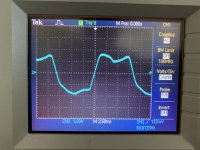
I have a Heathkit IG-72 Audio Generator. It's been working pretty well for me, albeit the signal calibration was pretty sensitive. Recently it's stopped working all together. I either get a screwed up signal (see attached), or something that's so high voltage it looks like a square wave even at 50V on my scope (Most output frequency selection settings result in the square wave, a few low frequency settings give me the screwed up wave). When I get the square wave, the tungsten bulb goes bright.
I'm looking for suggestions on where to start. I don't want to start pulling and checking parts at random, and nothing *looks* obviously bad. Tapping on the voltage adjustment knob, or some of the parts connected to the tubes causes the waveform to jiggle, for what it's worth.
Happy to provide any additional information you might want to see")
I'm looking for suggestions on where to start. I don't want to start pulling and checking parts at random, and nothing *looks* obviously bad. Tapping on the voltage adjustment knob, or some of the parts connected to the tubes causes the waveform to jiggle, for what it's worth.
Happy to provide any additional information you might want to see
Attachments
Hi,
My usual disclaimer: No familiarity with this instrument and I'm working only from the schematic.
Some scattershot suggestions:
Tubes check ok or same performance with changes to known-good tubes?
Do the controls "feel" flaky or noisy when manipulated? You could try contact cleaner on switches with special scrutiny to oscillator control, R20. I'm particularly suspicious of it because you mention occasional square wave overload.
If nothing obvious is revealed, I suggest voltage checks with a DVM or your scope, beginning perhaps with the power supply. There should be only a few volts of 120 Hz ripple at C6A with roughly similar amplitude on each phase, and even less ripple at C6B.
Next I'd check all the bias voltages at the tubes and look for voltages way different from the nominals noted on the schematic.
Scrutinize C8. Obviously, there's large DC voltage across it, but there should be low AC signal loss across C8 and any AC waveform present should be closely replicated on both terminals.
Keep us posted. Good luck!
Steve
Those are good tips BSST, thank you very much, exactly what I was looking for! The controls do "feel" flaky. The response will "wiggle" when adjusted, like it skews too high or too low briefly before returning to normal. Certain frequency ranges will work better than others. In the past, when it was working better, adjusting the oscillator control would cause the amplitude of the wave to suddenly jump; Within a certain range it would adjust as expected, then it would suddenly jump up or down 10-20x and then continue adjusting normally at this new range.
I have sprayed much contact cleaner into all the pots and switches. I should say the square wave overload has been getting worse. It used to be very occasional, then more occasional, then semi frequent, now it's basically constant.
I'll start looking at the things you suggested. I have no way of testing the tubes (unless I can test them with a meter and scope?). But I will check the caps and voltages.
It's normal behavior for the amplitude to "bounce" when it's perturbed by changes--- especially R20, but perhaps also to changes in R23 output control, to a lesser extent.
As an experiment, try exercising R20 through its entire range. It will likely vary from heavy clipping to cessation of oscillation. Ideally, it should vary smoothly between these extremes. You might also search for a replacement for R20. You can also substitute fixed resistors experimentaly to remove R20 from suspicion till the dust settles.
As an experiment, try exercising R20 through its entire range. It will likely vary from heavy clipping to cessation of oscillation. Ideally, it should vary smoothly between these extremes. You might also search for a replacement for R20. You can also substitute fixed resistors experimentaly to remove R20 from suspicion till the dust settles.
I assume you have looked for leakey caps, discolored resistors and such
If you have the manual. do the calibration first. check the voltages as shown in the manuals schematic. You should find a voltage that is way out of line. what ever is defective will be around the voltage test point.
JNunn
If you have the manual. do the calibration first. check the voltages as shown in the manuals schematic. You should find a voltage that is way out of line. what ever is defective will be around the voltage test point.
JNunn
I'm not sure, but it does seem concerning. Of course I have no experience with this instrument. Perhaps other members have this generator in their collection.
The schematic shows 320 VAC across the transformer secondary. What do you observe? Maybe V3 is weak? What do you observe at the filament winding? An additional experiment might unplug V1 and V2 and measure what happens to B+. I'm not sure what that would prove.
V3 could also be replaced with silicon diodes (1N2006 if memory serves. Needs checking). Edit: Should be 1n2007
P.S. What do you see at B+ with your scope? Does ripple seem inordinately high?
Last edited:
First check the signal across the agc lamp. The lamp should be "dark" if its operating correctly. The output waveform indicates the connection to the lamp or from the lamp to the feedback loop is open and the oscillation is saturated. My first guess is the 600 Ohm pot is open. The problem with be in that area.
This stuff is pretty tolerant of supply voltage and component tolerance. Levels and frequencies will shift but it will still work. If you adjust the operating level down the distortion will go down. That was a special option for the HP 400CD (H05) that McIntosh used for their clinics.
This stuff is pretty tolerant of supply voltage and component tolerance. Levels and frequencies will shift but it will still work. If you adjust the operating level down the distortion will go down. That was a special option for the HP 400CD (H05) that McIntosh used for their clinics.
V3 could also be replaced with silicon diodes (1N2006 if memory serves. Needs checking). Edit: Should be 1n2007
That should have been 1N4007.
Hi,
My usual disclaimer: No familiarity with this instrument and I'm working only from the schematic.
Some scattershot suggestions:
Tubes check ok or same performance with changes to known-good tubes?
Do the controls "feel" flaky or noisy when manipulated? You could try contact cleaner on switches with special scrutiny to oscillator control, R20. I'm particularly suspicious of it because you mention occasional square wave overload.
If nothing obvious is revealed, I suggest voltage checks with a DVM or your scope, beginning perhaps with the power supply. There should be only a few volts of 120 Hz ripple at C6A with roughly similar amplitude on each phase, and even less ripple at C6B.
Next I'd check all the bias voltages at the tubes and look for voltages way different from the nominals noted on the schematic.
Scrutinize C8. Obviously, there's large DC voltage across it, but there should be low AC signal loss across C8 and any AC waveform present should be closely replicated on both terminals.
Keep us posted. Good luck!
Steve
Stupid question, but where are you getting these reference labels, C6A, C6B, C8, R20? I don’t see them anywhere on the schematic or the manual.
Hi,
I found the manual on line and schematic is on page 39.
HEATHKIT IG-72 AUDIO GENERATOR SM Service Manual download, schematics, eeprom, repair info for electronics experts
In my copy, the ref des are low contrast, but C6A and C6B straddle the Filter Choke; the lamp, R20, and C8 are all near the cathodes of the V1 and V2.
I hope this is the appropriate schematic. Let me know if you can't download.
Steve
I found the manual on line and schematic is on page 39.
The only manual I've been able to find is this one, which only has 28 pages: DAYSTROM HEATHKIT IG-72 ASSEMBLY MANUAL Pdf Download | ManualsLib
It has a schematic on page 4, which is the same one you linked to. I don't see any of the labels you refer to on that schematic. I see two tubes labeled 6AU6 and 6CL6, I see C1, C2, R1, and R2. Everything else is simply referenced by value.
I've been searching for a more complete manual, but haven't been able to find one. I thought maybe this was all that existed. If you know where I can find a more detailed manual, I would *love* it.
HEATHKIT IG-72 AUDIO GENERATOR SM Service Manual download, schematics, eeprom, repair info for electronics experts
The above link works for me. I tried to attach as a file, but it's too large.
The above link works for me. I tried to attach as a file, but it's too large.
Manual
Hi,
Go to: Heathkit IG-72
DAYSTROM HEATHKIT IG-72 ASSEMBLY MANUAL Pdf Download | ManualsLib
I did download it, and its real great!
Hi,
Go to: Heathkit IG-72
DAYSTROM HEATHKIT IG-72 ASSEMBLY MANUAL Pdf Download | ManualsLib
I did download it, and its real great!
- Home
- Design & Build
- Equipment & Tools
- Heathkit audio generator producing bad signal or clipping, where to start?