Modding AURALiC Aries Mini
- By jean-paul
- Digital Source
- 37 Replies
Hi, does anyone else have experience with modding an Aries Mini? I think it is a well designed device (electronically) and the app is quite OK. It sounds very good as it has an excellent ESS DAC chip, is DSD capable, has mature software and it can be bought used for less than a RPI/good DAC combo costs. It certainly looks a lot better than RPI + DAC devices.
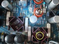
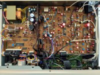
However, the device has a cheap fully closed casing which makes the device overheating itself. It has a quad core ARM CPU and a 802.11ac wireless card which both generate heat. The heat is transferred from the CPU to the shielding with a piece of silicone rubber. The shielding is fully closed. A kind of heatsink is taped to the inner upper side and the shielding makes contact with the heatsink but not very well. Of course heat sink paste was used in abundance 😉 After having examined the whole situation I conclude that cost savings were the reason to produce it like it is but that some corners were cut that should not have been cut. Auralic says they made a loss selling the Aries Mini and that may be so but some design choices were suboptimal.
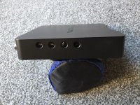
My first step was to determine the right place for the holes and to remove the PCB. Please note that before drilling the electronics and the heatsink have to be removed. Opening the case should be done upside down with a credit card lifting the front side of the bottom cover. Don't put the credit card too deep or the plastic hooks that keep the device together will break. I left the wireless card hanging on its antenna wiring as the connectors are fragile. A small piece of tape will keep the card outside the drilling area. I used tape on the sides to prevent drilling debris scratching the casings surface. Although having a cold I managed to drill the holes quite neat (I think 🙂) with wood drills and afterwards I deburred the holes slightly. I forgot to measure temperature before I took it apart but it was so hot that I feared the plastic case to deform. In case the owner has a white version one can tell the overheating as the white cases become yellow very fast exactly where the CPU and other "hot" chips are. According Auralic the heat does not pose a problem but I am quite sure the lifespan of the device will be years less because of the thermal effects on the capacitors and other SMD parts. Many owners take the wall wart SMPS out of the wall socket after use because of the generated heat. Unfortunately the device nor its power supply have an on/off switch.
After drilling holes in both sides, the bottom cover and in the SSD casing the upper side of the cover is now 40 degrees Celsius (at 22 degrees ambient) and feels only slightly warm. Adding just the holes on the left and right sides does not bring much if there are no ventilation holes in the bottom and SSD casing. There needs to be air flow. It helps to stick some rubber feet at the bottom to give it room to breathe.
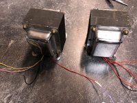
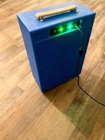
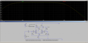
Next step is a linear PSU with true mains switch that I started building yesterday. Please let me know if you are also modding this device and what you have done to the poor thing 😀
However, the device has a cheap fully closed casing which makes the device overheating itself. It has a quad core ARM CPU and a 802.11ac wireless card which both generate heat. The heat is transferred from the CPU to the shielding with a piece of silicone rubber. The shielding is fully closed. A kind of heatsink is taped to the inner upper side and the shielding makes contact with the heatsink but not very well. Of course heat sink paste was used in abundance 😉 After having examined the whole situation I conclude that cost savings were the reason to produce it like it is but that some corners were cut that should not have been cut. Auralic says they made a loss selling the Aries Mini and that may be so but some design choices were suboptimal.
My first step was to determine the right place for the holes and to remove the PCB. Please note that before drilling the electronics and the heatsink have to be removed. Opening the case should be done upside down with a credit card lifting the front side of the bottom cover. Don't put the credit card too deep or the plastic hooks that keep the device together will break. I left the wireless card hanging on its antenna wiring as the connectors are fragile. A small piece of tape will keep the card outside the drilling area. I used tape on the sides to prevent drilling debris scratching the casings surface. Although having a cold I managed to drill the holes quite neat (I think 🙂) with wood drills and afterwards I deburred the holes slightly. I forgot to measure temperature before I took it apart but it was so hot that I feared the plastic case to deform. In case the owner has a white version one can tell the overheating as the white cases become yellow very fast exactly where the CPU and other "hot" chips are. According Auralic the heat does not pose a problem but I am quite sure the lifespan of the device will be years less because of the thermal effects on the capacitors and other SMD parts. Many owners take the wall wart SMPS out of the wall socket after use because of the generated heat. Unfortunately the device nor its power supply have an on/off switch.
After drilling holes in both sides, the bottom cover and in the SSD casing the upper side of the cover is now 40 degrees Celsius (at 22 degrees ambient) and feels only slightly warm. Adding just the holes on the left and right sides does not bring much if there are no ventilation holes in the bottom and SSD casing. There needs to be air flow. It helps to stick some rubber feet at the bottom to give it room to breathe.
Next step is a linear PSU with true mains switch that I started building yesterday. Please let me know if you are also modding this device and what you have done to the poor thing 😀