Nakamichi DR1 DC offset problem

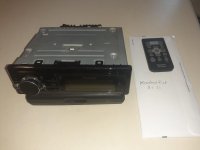
I took my Nakamichi DR1 out of hibernation of 20 years (bought new in 1994). I replaced the drive belts but one of the channels has no output. When I switched between Type I, II or IV positions there was an intermittent sound on the dead channel, but it would cut out again within a split second. I hooked the output to a scope and found that the dead channel has a large DC offset that can go from -4V (Type I position) to +3 to +4.5V (Type II or IV position). When the DC offset switched between negative to positive while switching between Type I or II position the sound would come on for a short time until the DC offset gets high again. It is like the DC offset saturated the amp. When I keep it playing for some time, the DC offset would sometimes come down low enough and the channel would play (but I can still see 1-2V DC offset).

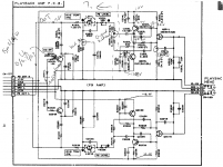
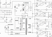
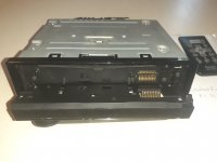
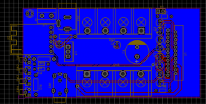
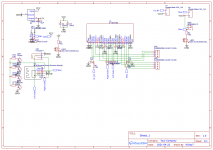
I found the schematic from the internet, and was able to isolate the problem to be in the playback amp PCB. I replaced all 6 electrolytic caps and in fact found a bad smelly one from the dead channel (C206 in schematic). I thought that would fix it but the dead channel is still dead. The DC offset is still there. I measured every point in the schematic and compared the measurements on both channels using a scope (while playing music), so I was able to see the signal plus DC offset. Both channels measured very closely except the output from the bad channel has a DC offset after the capacitors on the output side. The output is AC coupled so I couldn't figure out where the DC offset came from. Everything to the right of the dotted line in the schematic matched very closely between the channels but the left side has a DC offset in the bad channel.

Anyone has an idea what is going on?
Thanks.

Attachments

  • playback_amp.png
    playback_amp.png
    44.8 KB · Views: 156

A universal 'cookbook' relay delay using an LM555 timer.

The following circuit is a copy of an LM555 (equiv NE555) based relay delay circuit I designed around 20 years or more ago for muting the output of a preamp. The design goals were reliable operation and the ability for the circuit to give the full mute period if the power supply was cycled quickly on and off. Some recent threads on diyAudio have enquired about such circuits.

The design offered here is done so as more of a 'cookbook' type of design that can be altered and changed to suit individual requirements rather than a fully documented construction project.

Practical points:

1/ Ideally the circuit should be fed from a small auxiliary supply of limited 'reserve' capacity. This means a supply of minimal reservoir capacitor size which ensures that the relay drops out very smartly on power off. A single half wave rectifier and smallish cap (perhaps just 220uF) is the kind of thing that would work well. Ensure the ripple rating of the cap is not exceeded. A little series resistance added to the supply works wonders in dramatically reducing peak ripple currents.

2/ The delay can be altered by means of the time constant of R3 and C4. You should ensure that the combination chosen is suitable. For example it is no good using a 10 Meg resistor and a relatively large and leaky electrolytic cap.

3/ The design has not been tested with either the low power or CMOS versions of the chip. In practice the relatively high draw of the original LM555 can be useful in ensuring the rail powering the device collapses quickly should the power be cycled on/off during the initial period the delay is operating.

4/ The LED indication at the right is something I didn't build into the original, however it could be useful for some. The series connected LED + resistor network seems the simplest method of achieving this and uses the fact that the 555 output switches between supply and ground thus effectively shorting out one or other of the indicators. The series resistors are scaled to suit your LED's.

5/ The original 555 has a wide operating supply range of 5 to 16 volts and a source/sink ability of up to 200ma.

6/ It is very important to decouple the NE555 very close to the power pins in order to avoid false triggering. My favourite approach is to neatly solder a small high quality 10uF cap directly across the pins.

The following images show the circuit diagram, the relay current vs supply voltage in normal operation (the power is on for 1 minute) and finally the behaviour of the circuit in response to rapid cycling of the supply. This is where using a power supply with a small time constant is advantageous.

Edit history...

.asc file updated to enable it to run using default LTspice models.

Attachments

  • Circuit Diagram.jpg
    Circuit Diagram.jpg
    284.9 KB · Views: 419
  • Normal Operation.jpg
    Normal Operation.jpg
    220.3 KB · Views: 418
  • Rapid Cycling of Power Switch.jpg
    Rapid Cycling of Power Switch.jpg
    229 KB · Views: 391
  • 555 Relay Delay.asc
    555 Relay Delay.asc
    3.1 KB · Views: 100

Waynes BA2018 and Biamp 6-24 crossover, the basics.

Waynes BA2018 and Biamp 6-24 crossover

Just having purchased both of these I have the following questions.

With Waynes BA2018 as a preamp I seem to have made a mess of the surface mounted Jfets. They are out of stock at Mouser and Digikey. Does DIY have a stock so I can attempt to replace them or am I relegated to getting the whole kit to try again? I purchased a new soldering iron for the job and I expect I will need to start again to get this happening. I propose gluing the little blighters with a small dab of contact before a careful soldering under magnification. Any help gratefully acknowledged.

With the crossover I have read countless pages searching for the BOM. I know it must be somewhere but can't locate it . Do I have to just read the board? Nelson also said there was a build thread by 6L6. It's certainly not listed anywhere I can see.
I have also not been able to understand the way we work out what capacitor values are needed for a certain frequency. Sorry I am right down there before most of you ever heard the word electron. So I'm wanting to put frequencies up to 300Hertz through my transmission lines and everything else goes up. I can't understand the graphs that keep making everyone so happy. Just failed that intelligence test.
Maybe one of you kind boffins could help me to work this out using that lovely looking crossover board . Also those big side caps are a total mystery as to their value.
In my defense I built an Aleph J that has been flawless for a few years and am slowly getting the stuff together for a second one. My soldering is not attrocious and I can get things right with a small amount of assistance.
Cheers.
Dan

Designing transformer coupled amplifiers with Ge transistors

Hi,

most of us might know the »Deacy« amplifier that John Deacon of Queen had built from an old radio and which is responsible for Brian May's signature guitar sound. It's main features are the germanium transistors used in any stage and it's transformer coupled output section. Even phase inversion was done with a transformer.

As there are many Ge transistors in my stashes, I have the idea to design an amplifier with these features. I think the math can easily be done for the output transformer, but I'm completely lost with the PI tranny. How do I calculate the power transistors' drive power demands and the winding ratio?

Best regards!

Remote Controlled (RC) Volume Control Kits - Overview wanted

I am looking arround to RC volume control kits, at best include envelope (enclosure) and RC transmitter hand set unit (motor pot or dig. controlled). Please note: Not digital attenuator, but digital controlled attenuator.
On ebay there are a wide range of bidders without envelope and only partly solutions (either only RC transmitter/receiver unit or only volume control unit with SPI controlled pins), but I want to have a completly kit like Vellemann K8022.
At follow this no longer available Vellemann Kit and some other examples:

A: RC Motor Analog-Potis
1) Velleman K8022 PASSIV Preamp with remote control
K8022 Passiver Vorverstärker mit RF-Fernbedienung im Sly-electronic Shop Berlin
http://www.sly.de/bbilder/k8022.jpg
Fernsteuersender Handsender 2 Kanal VM130T - Lüdeke Elekronic Elektronikhandel
http_www_velleman.eu/distributor/products/view/?id=345984
associated RC transmitter:
http_www_velleman.eu/distributor/products/view/?id=374092
2) RCLL, Remote Controlled Line Level Volume Control
Audioplex RCLL-1 Remote Controlled Line Level VC
http://www.audioplex.com/RCLL1 revised.pdf
3) MK161 - IR 2 Channel Remote Receiver Kit
MK161 - IR 2 Channel Remote Receiver Kit - Ramsey Electronics
4) MV-04 motorize remote volume control
DIYCLUB
5) Remote control audio kit
Dantimax - Remote control audio kits

B. Remote Controlled Switched Resistors by Relay
1) The remote control paratactic volume control
http://www.diyaudio.com/forums/solid-state/56009-remote-control-paratactic-volume-control.html
2) Audio Volume Relay Attenuator with IR Control
Audio Volume Relay Attenuator with IR Control
3) Remote volume control board, using relay - Halcro also use relay on their DA10 pre amp
DIYCLUB
4) VolControl, Volume/attenuator control board
Dantimax (elektronik) - Control_boards
5) TentLabs Volume control
Volume control
more kits:
DIYCLUB

C) Semiconductor switches (C-MOS series)

1) Remote Controlled Stepped Attenuator
Welborne Labs Remote Controlled Attenuator
2) RC-16 Remote Volume Control (looks like that one from Cyrus III and Cyrus IIIi / Cyrus 3i)
http://www.oxmoor.com/files/cut sheets/DCA-2 RC-16 cut sheet.pdf
RC-16 Remote Volume Control - Oxmoor Professional Audio Products

And here several IC solutions for volume control application:
Digital Potentiometer
Digital Potentiometers and Capacitors (ISL22317)
Digital Volume Control
Volume Control - Volume Controls (CS3318)
2-Channel 78 dB Audio Attenuator
LM1972 - Micro-Pot 2-Channel 78 dB Audio Attenuator with Mute
Stereo Audio Volume Control (PGA2310-2311-2320-4311)
Audio - Volume Control - PGA2310 - TI.com
Electronic Audio Attenuator dc controlled (MC3340)
http://www.datasheetcatalog.org/datasheet/motorola/MC3340.pdf
MAS9116 - Stereo Digital Volume Control
MAS9116 pdf, MAS9116 description, MAS9116 datasheets, MAS9116 view ::: ALLDATASHEET :::
Dual-Channel Digital Volume Control with CMOS switch 4066
http://www.electronicsforu.com/efylinux/circuit/feb2003/aug99_dualchannel.pdf
Digital controlled stereo audio processor TDA7313 (ST)
http://ampslab.com/PDF/tda7313.pdf
http://www.st.com/stonline/stappl/p...type=4&tname=TL_DATASHEET_TREE_X_DOC&latest=N
Maxim DS8102 - the new volume control chip
http://datasheets.maxim-ic.com/en/ds/DS1802.pdf
DS8102 Dual Delta-Sigma Modulator and Encoder - Overview
DIY: high end DAC and digital volume control | Flickr - Photo Sharing!
TDA7439 (Linn Kolektor) THREE BANDS DIGITALLY CONTROLLED AUDIO PROCESSOR (ST)
http://www.datasheetcatalog.org/datasheet/stmicroelectronics/4291.pdf

In the attachement various CMOS solution schematics.

I want to have a good overview about completly kits like the no longer available Vellemann K8022.

Thank you for additional proposals.

(copyrighted images removed by moderators)

Advice for active triamping

Hi There! I'm planning to actively triamp my speakers. My current setup is as follows: pc (with Rew, RePhase and Eq Apo > Topping D50s > ZeroZone Irs 2092 monoblocks https://it.aliexpress.com/item/32904122947.html > Wharfedale Linton Heritage https://www.wharfedale.co.uk/linton-heritage/ (sensitivity 88-90 db, crossover 600 and 2400 Hz). Since the Lintons are three-way speakers, I'm wondering if I could remove the passive crossover and use the ZeroZones for the woofers and separate amps for midrange and tweeters. The crossover may be implemented in the digital domain with RePhase and Eq. Apo. A six-channel interface would substitute the Dac.
I have several doubts. First: is the entire endeavor worth it? After all, with Room correction I already have a quite flat response - see the attached image from Rew. Can removing the passive crossover increase the dynamic range and reduce the distortion? What about "semi-active" bi-amping: that is, disconnecting only the woofers from the passive crossover and using only two amps: one for woofers directly connected to drivers and one for mid-highs, connected to passive crossover. In this case, I could use a high-pass filter at, say 200 Hz.
Second question: which interface? Something from Motu or Focusrite?
Third: which amps for midrange and tweeters? I assume that I will be able to regulate the different sensitivities modifying the gain of the different channels. For midrange I've thought to amps like Topping PA5, Sabaj A8, SMSL DA 9, Aiyima A 07 or 08.
For tweeters: Topping PA3s, Sabaj A 10, SMSL A100, Aiyma A04.
Thank you in advance and sorry for my english.
Leonardo
Stnov.jpg

Looking Drivers for subwoofer, help me to choice which one.

Hi, im from Argentina and here are not easy to find drivers (12-15-18") at good prices.

After searching a days for sellers and prices, i found this ones.

18 Inches

18WS600 (180USD)
Fs...............................................33 Hz
Frequency response @ -10 dB . . . . . . . . . . . . . . . . 35 to 3,000 Hz
Sensitivity (2.83V@1m) averaged from 100 to 500 Hz. . . . . 98 dB SPL
Xmax (max. excursion (peak) with 10% distortion) . . . 3.8 mm
Xlim (max.excursion (peak) before physical damage) .. 21 mm


18SWS1000 (210USD)
Fs...............................................36 Hz
Frequency response @ -10 dB . . . . . . . . . . . . . . . . 36 to 2,000 Hz
Sensitivity (2.83V@1m) averaged from 50 to 150 Hz. . . . . . 96 dB SPL
Xmax (max. excursion (peak) with 10% distortion) . . 6.75 mm
Xlim (max.excursion (peak) before physical damage) .. 21.0 mm

18FH510 (250USD)
Fs...............................................30 Hz
Frequency response @ -10 dB . . . . . . . . . . . . . . . . 30 to 2,500 Hz
Sensitivity (2.83V@1m) averaged from 50 to 150 Hz. . . . . . 98 dB SPL
Xmax (max. excursion (peak) with 10% distortion) . . 9.25 mm
Xlim (max.excursion (peak) before physical damage) .. 21.0 mm

18FP1030 (350USD)
Fs...............................................35 Hz
Frequency response @ -10 dB . . . . . . . . . . . . . . . . 36 to 1,600 Hz
Sensitivity (2.83V@1m) averaged from 50 to 150 Hz. . . . . . 98 dB SPL
Xmax (max. excursion (peak) with 10% distortion) . . 12.45 mm
Xlim (max.excursion (peak) before physical damage) .. 23.1 mm


15 Inches
15PWPRO (75USD)
Fs...............................................47 Hz
Frequency response @ -10 dB . . . . . . . . . . . . . . . . 40 to 4,780 Hz
Sensitivity (2.83V@1m) averaged from 50 to 150 Hz. . . . . . 94 dB SPL
Xmax (max. excursion (peak) with 10% distortion) . . 5.mm

Any other value to check to compare drivers?

I want to at least go down to 20hz and no problem with box size. Any box will be OK.

Audio focused beginner resources for electronics?

I am looking for sites/books/videos to learn about building audio components like amps, switches etc. I have a mechanical engineering background and am in the middle of an amp build with premade boards and power supplies. But eventually I would love to design and solder my own boards, like a preamp with volume & input control and display.

Fatman iTube DC Offset Issue - Does Anybody Else Have One?

Hi folks,
I’ve recently purchased a little Fatman iTube (silver mk1). I’ve cleaned up the pot and it sounds good to my ears, however the DC offsets at the speaker terminals are -130mv and -140mv which is much higher than I am used to with other amps.

The iTube is a valve pre-amp section (6n1) coupled with a TDA7265 chip amp for the power section.

I have measured the DC at the input pins of the chip and all seems well there. I note on the schematic of the chip that a feedback capacitor is omitted in the data sheet and this appears to be the case on the iTube PCB too. Could this be the issue?

I’m curious if anyone else had one of these and what their offset is. Perhaps it’s just as it was when it left the factory?

Steve

The DIY Midrange Dome Teggstreme Driver (or the epoxy calcium carbonate matrix dome)

Calcium carbonate compounds can make very successful structures and are found e.g. in eggshells. The matrix of eggshells is made of 90% calcium carbonate, and eggshells show some remarkable mechanical properties. So, then why calcium carbonate, as to my knowledge, has never been assessed as a material or compound for midrange or high frequency domes?

Textreme is carbon an epoxy. Epoxy is the binder for the otherwise flexible carbon fabric. And carbon acts as a «filler» for the epoxy resin, providing tensile strenght for the cured resin. Think in an analogy now: Instead of flexible carbon fabric, now take an eggshell as a static, calcium carbonate matrix filler for the epoxy resin. Simply think of teggstreme, so to say ...

As eggs include nicely dome-shaped parts, you could easily resort to an egg to assess the question, wheter calcium carbonate is suited fore midrange domes. An egg, as is, might result in an approx. 2-incher, then. So, lets make a midrange dome driver out of an egg, some drops of epoxy and of an outranged midbass driver. We will hopefulle end up with an eggcellent result. And for shure it will be an eggxeptional construction.

Lets go, then:

1. Choose an egg, take a handsaw and start smoothly sawing – if the egg is of decent quality from well-fed chickens, it will not brake. If instead several eggs brake, one after the other, then you may change your egg supplier. You will discover that the surface of a robust enough egg is quite resistant to a usual HSS saw blade, not unlike a ceramic surface, until you have managed to make a first groove. You have to be steady, delicate and patient.

2. Then you will have to take away all (!) skin structures from the inside of the egg shell. You can peel the main skin right away. But then you will have to scratch repetitively and for a quite long time the inside of the shell with your fingernails, until you really scratch on the calcium carbonate structure. Cleaning once and then with water from the tap helps. Let then the eggshell completely dry.

3. Carefully and smoothly sand the cutted edge with a sheet of sanding paper lying on a plane tabletop. 120- or 180-graded paper do well, no coarser, not to split small fragments away. Sand until the rim is more or less on one single plane.

4. As the eggshell is highly porous and fragile at the same time, you may reinforce it by applying epoxy into it. Do not laquer it, but gently work some expoxy into the eggshell by using your gloved (!) fingertips. Then wipe the spare epoxy away with a Cleenex or so.

5. When the epoxy has cured/hardened, the dome already is much more rubust and has gained some moderate elasticity. You may then apply a second, very thin layer of epoxy, then wait for it to get sticky, and then you may add some carbon rowing filaments.

6. An eggshell alone does not make a midrange. For a first assembly, any standard cone driver can be dismantled. In this case, it was a 6.5-inch Audax HDA driver. With scissors, the membrane may be trimmed down to a residual cone slightly larger than the dome circumference. This residual bit of cone will then act as the dome carrier cone.

7. Glue the dome onto the carrier cone. To insure a neat fit, eventially stuff some carbon rowing, slightly moisted with epoxy, around the rim of the dome, into the groove between the outside of the dome and the carrier cone.

8. The moving assembly will never be dynamically symmetric. The asymmetry might be slight, but may produce substantial tilting forces and maybe even dynamic rub between the voice coil and the walls of the magnetic gap. In this case, you may try to hand-tune this asymmetry by adding a small weight at the right place into the groove formed by the dome and the carrier cone.

On the To-Do-List now are some measurements, which hopefully I will be able to perform in some days.

Apart from the fun, the immediate reward of this project was … the further processed, main waste of the membrane construction process: It became a delicious fried egg.


Midregg.jpg

Denon POA6600 under restoration

Good evening to all,
Obviously, this is my first post on this forum, and although I have been looking at the threads for a long time, please excuse me if I am unclear or incomplete. Thanks to many of you, I learned a lot about the DIY audio.

The story is as follows..
I clone/restore amplifier by the attached schematic. The original PCB is in very bad condition and is not repairable, so I decided to clone the board as close as possible to the original.
Once all the elements were soldered in place, I started to check the amp. DC offset is about 4mV.
However, the amplifier oscillates at 1.4MHz, 1V RMS near to pure sine. The volume control is fully turned left, no load at the output. The idle current is affected by the oscillation. The oscillation is also present at the output of the VAS (L501 II R533).
I cut the link between L501, R533 and the next stage. That stops the oscillation at the output and the adjustment of the idle current become possible. No oscillation at the output of the VAS either.
I reconnect the link and check with 1kHz at the input to see the reaction. I started from 10mV to 1V. The clipping point is about 1.1V. On the low levels the 1kHz is affected by the oscillation. Rising the amplitude suppresses the oscillation and at 0.5-0.6V it disappears.
I noticed that the oscillation was affected when I tapped the body of the C523 or C524 with tweezers. The level is halved and sometimes completely disappears. The oscillation is also affected by the Volume potentiometer. In the fully left and fully right position it is about 1V, but when it is in the middle the level drops to 0.5V.
Very strange behavior. Any idea or advice on what to focus on to solve the problem? It will be the worst if it turns out that the reason is in the design of the board ...
Many thanks in advance!
1643479421574.png

1643479464968.png

1643479501096.png

Attachments

  • Denon 6600_2.png
    Denon 6600_2.png
    329.6 KB · Views: 114

Feedback and distortion in Single Ended amplifiers

Hi everyone,

My name is Mark and I have been an audio enthusiast (not quite an audiophile) for over 30 years. Starting out on a very low budget and since then both acquiring and building better and more advanced audio equipment. Although my hearing between 11 kHz and 15 kHz faded over the past 20 years, my fancy for Single Ended amps never did. I just happen to be an engineer also.

Having built a 300B amp some 20 years ago, I now decided to create my own and (at least partly) original design. I didn't want to simply copy on of the 100 designs that can be found on-line, and that have been going around for 100 years. I now finished the design and documented it (see attached).

This design distinguishes itself in the fact that;
  1. Every aspect of the design is documented including background theory, calculations and rationale
  2. It uses my own 300B self-bias circuit design (using DN2540 that is now in supply again at Reichelt.com)
  3. It uses my own driver stage design using Negative Feedback (yes, feedback... and with good reason)
I will argue that feedback is a bad thing in a Single Ended amplifier, in case you place your output stage within the feedback loop, which is what (almost) every 300B amp schematic with feedback that I've seen is doing. I do believe it can be an interesting read for those that aren't more knowledgeable than me ;-) If you are, than please catch my errors.

1645220309018.jpeg
1645220656735.jpeg


*********
UPDATE
*********
The amplifier has now been built I have been listening to it (with and without NFB to compare) for a couple of days. The final schematic has been attached to this thread.

IT SOUNDS AMAZING. I have written my listening impressions in document 300B_R06 attached for those interested. It's the last few chapters. I'm guessing at this point that 300B tubes are MUCH harder to drive than people think, but if you take control (very low Z-out of the driver) of what happens at the grid of a 300B, the payoff is amazing.

Kind regards,
Mark

Attachments

Capacitor Question

I’m staring a new thread on this since my old post has my questions along with others questions I wanna make it less confusing .

Anyway I’m rebuilding a 10k amp and noticed the amp has Sam Young caps in it .

i tested the rail caps which are supposed to be 1800uf 200v caps .


Some of the caps tested good while others tested not so good .

2 tested at 1660uf another at 1200uf and the esr varies from 2.4 to 1.6 .

I’m going to replace all of the rail caps .

Since the rail cap readings are all over the place wondering if this would be the cause of the amp self destructing when I installed it in the vehicle?

Nelson Pass and Michael Rothacher Presenting at Burning Amp!

Two of our five amazing presenters!

Online Event via Zoom!

Saturday October 16th, Noon-3:00 PM PDT (GMT-7):
Steven Dear, Audio Perception,
Demian Martin, New Tools and Techniques for Audio Measurement
Andrew Jones, Issues in Loudspeaker Design

Sunday October 17th, Noon-3:00 PM PDT (GMT-7):
Michael Rothacher, Weird Amps
Updates on Amplifier and Speaker Build Camps
Nelson Pass Current Topics

And a live Q&A with presenters each day. More to come!

Tickets are available:
Burning Amp Festival '21 Tickets, Sat, Oct 16, 2021 at 11:30 AM | Eventbrite

Output transformer winding with Line Out tap

There are guitar amps (Ashdown LB30 is one, see attached file) with a line-out provided by a tap on the output transformer . This would seem to be a way of using the tone created by a small SE amp and boosting it to gig levels with a power amp. Does this work as described or are there other factors involved? And how would you best implement it when winding a transformer?

Attachments

  • DI winding.png
    DI winding.png
    58.3 KB · Views: 228

Conrad Heatsinks gone ?

Hi Guys,

Has anybody recently had any success trying to contact Conrad Heatsinks?
I am getting the impression they have gone out of business.

I've been attempting to get a shipping quote to New Zealand.

I've tried doing an enquiry through their website but the form has an error at the submit order stage.
I've also tried emailing them directly but have received no reply.

Toastie Rotel RA-840BX4

Just got this amp, noticed one of the power resistors on the output stage was toast. In the schematic it suggests 2W, so to make sure it didn't happen again, I ordered some 5W replacements, installed them, recalibrated as per service manual, but after about an hour of use, I noticed the amp could fry an egg on itself, I have nothing above the amp, so it has free airflow all around it, yet it is ridiculously hot.

Service manual suggests I should wait 5 minutes, then calibrate for 2.5mV between TP3&1 / TP4&2 and 0V between 1&E1 / 2&E2. I followed this, but the voltage continued to increase between test points, so I left it warming for about 30 minutes until it stabilised, then calibrated. Now after an hour of use it is working more like a heat generator than an amplifier. Sound doesn't appear to be affected in any way.

Possibly not related, but the mono switch only seems to work on initial power up when the amplifier is cool

White noise playing back DSD through ES9038Q2M DAC

Hello everyone! I'm here because I thought I'd be able to achieve something awesome by buying a couple of things from China and plugging them together, and that didn't turn out quite as planned. 🙄

I have a Pioneer DVD player that outputs DSD over its HDMI output, so I wanted to get an HDMI-to-I2S audio extraction board, connect that to a nice DAC, and get amazing audio quality on the cheap. Unfortunately, when the DVD player outputs DSD audio, the DAC introduces a bunch of white noise that gets at least as loud as the music it's supposed to be playing. Sometimes playback will start with no noise at all, but it will gradually increase.

I've tried two variations of ES9038Q2M DAC board: this one and this other one. I've also tried two different HDMI audio extraction boards: this one and this one. All combinations exhibit the same behaviour.

I tried introducing an I2S isolation board but that didn't help, maybe because there are design considerations I need to take into account but didn't. I also tried series resistors and pull-down resistors on each of the channels, but that didn't help either. I attached a cheap logic analyzer to the HDMI board output, and I can see (as well as the 24MHz sampling frequency of the logic analyzer will allow) that the ones and zeroes are where they should be when they should be. My lame multimeter shows that the voltage on the signal pins is around 3.3V, which is within the 5V that the datasheet says the ES9038Q2M can tolerate. My cheap digital scope shows what looks to my eye like random noise on the analogue output when the problem occurs. I've tried powering it from a couple of 12V wall-warts that came from external hard drives, and also from the ATX power supply from a PC - that made no difference to the outcome.

I think I've reached the limit of what I can achieve without further guidance - I've scoured the internet trying to find similar issues but I didn't get anywhere. Does anyone have any ideas for what I can investigate next or what I should revisit and how? Is there something I'm missing or something I can try?

  • Poll Poll
Pavel Dudek's super Gainclone group buy

Colour of the pcb

  • Black

    Votes: 31 37.8%
  • White

    Votes: 12 14.6%
  • Red

    Votes: 14 17.1%
  • Blue

    Votes: 13 15.9%
  • Yellow

    Votes: 3 3.7%
  • Green

    Votes: 13 15.9%

http://www.diyaudio.com/wiki/index.php?page=LM4780+Pavel+Dudek+GB

Finally Pavel has said OK to run a group buy deal. Please sign the list above if you are interested. The first step is only an interest check.

Building speakers into Entertainment Center

Forgive me if this is the wrong forum for this question, but I'm about to build my second set of speakers and could use a bit of advice. I built a set of pensils a few years ago, but for this new build I want to build a custom entertainment center and build the speakers into the actual cabinetry. I know I could simply buy a set of in-wall speakers for this use case, and mount them into the cabinets, but since my entertainment center is going to be 16" deep, it seems like I could get better results by custom building something to take advantage of that depth instead of using in-wall speakers that were designed to be installed in 4" thick walls.

Anyway, here's a sketch of what I have in mind. I plan on doing a 3.1 set up. This is our main TV in our family room area, so I feel like I need a center channel for the TV, but the stereo performance is just as important to me. My question is, can anyone recommend a kit that would function well if built into an entertainment center? I can make the speaker "compartments" any size I want, but in this sketch I have them at 16x18x16", so I was thinking something similar to the Seas A26 kit from Madisound might do the trick?

Entertainment Center.png

Dashboard cover speakers of a 97 Brazilian VW.

I own this 1997 VW Quantum, which is a version of the VW Passat SW and it has a pair of speaker on the left, driver's side, and another pair on the passenger side. The configuration is mid-range + treble on the door and bass just over the dashboard cover. Considering it has a 4 cylinder 1.8L gasoline engine, it seems to me, the idea was to place all the bass over the cover to mask the engine roar, am I right? If so, it must have a low-pass before the dashboard cover and a high-pass just before the door speaker. In this case, what should be the cutt-off frequency of the filters, because I think the cross-over filter is not deafult as I bought it second-hand, maybe third or fourth-hand. Picture 1 and 2 are random while the others are the actual car.

1643473097486.png


1643473218257.png


1643473339583.png


1643473365421.png

1643473384110.png

Home theater subwoofer

Yello!

I'm building a home theater subwoofer. I have managed to get hold of 8x cheap Logitech Z-2300 sound systems. I'm going to take their subwoofers and put in a new enclosure. I am 99% sure that the Z-2300 subwoofers are the same as a Tang Band W8-670C (see pdf below). Could someone help me design an enclosure with as low a tuning frequency as possible.

These subwoofers have the FS at 40Hz, is it then possible to tune a enclosure below this or what will happen then?

The place I have is 2,478mm wide, 450mm high and max 500mm depth. (It will be under the projector screen)

Thanks
//Rian

Attachments

More scheming about triode preamp plate voltage...

I found lots of feedback directed at other people who want to run 12AU7s at extremely low plate voltages, (e.g. 12V) but what about something more realistic and easily obtainable, which for me is probably somewhere between 150-180 volts of raw B+? I have two nice little identical toroidal power supply transformers which, with their 30V secondaries coupled, put out exactly what goes in, 120V, so I'm guessing post-bridge-rectifier-and-double-pi-filter, probably another 40 volts on top of that. All I'm attempting to do is get decent "warm" coloration at unity or maybe slightly more than unity gain from a homebrew preamp using a 12AU7 which I have lots of, or a 12AX7, of which I only have a few to play with. Would a little over half of the 300V rated maximum give enough S/N headroom for that application?

Thanks in advance for everyone's sage input on this. 🙂

-e

Lii Audio Silver-8, need help with a bookshelf design please!

Hi!

I have a pair of Lii Silver 8's that I'd love to use in a bookshelf enclosure, something compact ... I've been experimenting all week, and out of my 6 or so prototypes, they all have one thing in common - A MASSIVE nose dive at 110hz .. is there anyway to get to at least 70 without a massive transmission line box? Thanks!
  • Like
Reactions: Chemarcelo

Looking for thoughts on cosmetics of upcoming EICO HF-87 Restoration

I am looking for your thoughts and opinions on how, cosmetically, to restore an EICO HF-87 I recently acquired. I picked up the HF-87 that had been in Sheffield Lab Recordings (sheffieldlab.com). Some of you may have seen this advertised, but I got it for much less than advertised, partly because of my previous restoration of one. The studio had converted the amp to rack mount and fixed bias. While quite competently done from an electrical standpoint, it leaves a lot to be desired on the cosmetic side. No matter what happens, I am doing a 100% full strip down restoration. While functional, the caps are shot and so are the tubes. It needs a complete overhaul.

My big question is, do you think I should revert it back to the original condition chassis (no rack mount) and self-bias or restore it as the studio had it with the custom rack mounting, but in a way that looks very nice? Definitely a new front panel.

I have attached a pic of one I did years ago that had a bad power transformer. Either way, I will likely lose the green paint... but I am really split on restoring to original(ish) vs. leaving it with its unique history from the company. I really could go either way and be happy.

What does everyone think?

Attachments

  • 001.jpg
    001.jpg
    129.7 KB · Views: 190
  • 002.jpg
    002.jpg
    94.7 KB · Views: 179

Need help with poorly built HH Scott LK72B

Hello people.

I've reached that stage in my project where I doubt my work, my self and my ability to follow though.
Picked this up for $50.00. In trying to find the proper schematic I realised the builder wasn't focused.
Now I've built a pair of Eico hf30 clones from some Baldwin amps I acquired; survived their spark tests
and I even kept all the smoke in them! So I can read a schematic. Back when I had a Metcal and Pace I
could solder but now I'm using a stained glass soldering iron (don't ask).

So....if you don't mind, please examine the pictures and let me know f you see something I missed or that doesn't make sense.
(I stopped working on it about a three years ago!)

Thank you in advance,
Respectfully yours,
Todd

Cobbled together SE stereo guitar power amp

I've been gradually pulling together the makings of a stereo guitar rig - got a nice rack preamp, stereo effects, stereo 4x12, etc. Still need a power amp though, and as I thought about it I realized that I've got all the parts that I need already on hand - a couple of SE 5K:8 OTs, a PT with enough oomph for something relatively low-power, tubes, a sufficient choke, and even a chassis that will work. I put together this design, and would love to hear any feedback anyone might have.

It uses an E1148 (effectively half of a 6SN7) to drive a 6P7S (basically an 807). It sims out to yield 10WPC with 9% THD from a 1VRMS input. Each side idles at about 65mA (21W) on the plate and 4.1mA (1.2W) on the screen. I can't get more headroom out of it because I'm limited on B+, but 20W of "guitar clean" is way more than I can see myself being able to use at home anyway. PT doesn't have a bias tap, so I'm having to do a cap-coupled supply. (Cathode and back biasing, both cost too much Vak.)

The 100K input grid leaks will be individual volume pots. I thought about putting in a presence control, but there's barely any NFB to speak of, so I don't think it would be all that effective.

Anything boneheaded that I'm overlooking here, before I prototype it?

Attachments

  • 6p7s Stereo SE.PNG
    6p7s Stereo SE.PNG
    31.2 KB · Views: 210

Seeking Critique of first Tube Amp Design

Hi All,

I am just about to assemble my first tube amplifier and have designed what I think is a workable SE UL circuit, of course subject to minor tweaking once built.

I already have most of the parts listed, but wanted to run it by everyone before I start drilling holes and cutting transformer leads.

I have used a mosfet follower as it allows me to use one hammond power transformer with no requirement for elevated heater supplies.

Please critique at will, I am particualy interested to know about the power suppy design - working with tube rectifiers is new to me, I believe I am right on the edge of the 5AR4's capability.

The amp will initially be run with EL34's but I may change the cathode resistor and run KT88's at some point. I realise the power supply input cap and resistor may need some tweaking to provide the correct anode voltage.

Proposed key components as follows:

Power transformer: Hammond 374BX, 750V CT:
https://www.hammfg.com/files/parts/pdf/374BX.pdf

Power supply capacitors,would love advice on these as I don't have much safety margin: 500V Rubycon LXW series:
https://au.mouser.com/datasheet/2/977/e_LXW-1600626.pdf

Choke: Hammond 193J (10H, 200mA):
https://www.hammfg.com/files/parts/pdf/193J.pdf

Output Transformer: 5K Toroidy TTG-EL84SE:
TTG-EL84SE - Tube output UL transformer [5kOhm] EL84 / 6V6 SE - Shop Toroidy.pl

Any advice is appreciated!

Greg

Attachments

  • ULAMP.PNG
    ULAMP.PNG
    419.4 KB · Views: 625

8-channel DAC + board for low-power application

Hello everyone,


I am looking for an all-in-one 8-channel DAC solution for a low-power application. Four pairs of channels will be fed from the DAC to stereo amplifier boards with <15 W of RMS power @ 8 ohms.


The only product I have found so far is the following:


8 Channels 384kHz 32bit ES9016 PCM DXD DSD Audio DAC - DIYINHK


However, I don't need such a high resolution DAC—96 to 192 kHz and 16 to 24 bit is sufficient.


Sound quality is still important, but I am hoping that someone knows of a cheaper DAC + board setup. I need USB-C (Windows compatible) to 8 channels of analog line-out.


Thank you!

Aleph J Source Resistor Discolouration

Hello Everyone!

After being out of my system a little while I decided to hook up my Aleph J again. Before putting it into my audio rack I powered it back up and let it warm up for an hour to check if the bias or offset had drifted at all and to my delight they were exactly as they were a year ago with a bias of 420mv and almost spot on offset at -0.1mv

The one thing I did notice right away is that all the big 3watt Panasonic source resistors that were once a very light blue were now a light brown colour. There aren’t any burn marks or discolourations that I can see on the pcb, and as per the build recommendations the 3w resistors are elevated from the board for heat dissipation (about 1/4”) and the amp seems to be functioning as expected.

I have read that the J runs “very hot” compared to other FW amps so I’m not sure if this is a problem or not. The amp is well ventilated with nothing on top or around it and the heat syncs are at approx 51deg C. It’s also my first Diy build from a few years ago.

Should I be concerned?

Turntable Motor does/ does not spin

I've got a turntable that sometimes will turn and sometimes will not. Pulling off the platter, turning it upside down, etc., you can easily find the little motor. Belt-drive type.

This motor has a spindle that sometimes will spin and sometimes will not. When it doesn't go on of its own accord, a gentle twist and the spindle will take off and run smoothly.

How do I convince it that it would be happiest spinning away all the time?

May have found the source of "glare" in my system

I have been fighting "something" ill defined but I can hear and my wife very clearly, that is unpleasant is some recordings, played on some electronics on some speakers, for a good 10 years. I think I have finally cracked the code, so to speak.

Yesterday, I was able to make the symptom come and go based on which tweeter was in play, and which DAC I was using. Yes DAC.

The symptom is an upsetting "glare" for want of a better word. I tracked it down to a narrow frequency range, around 3100 Hz. Any recording engineer knows that band well. The good ones at least, which may be part of the problem. My theory is this being in the most sensitive part of our hearing, we may be genetically biased as it is the shrillness of a baby scream in distress. It is most evident on cymbals, trumpets, and soprano voices. Things strong in that band but have copious strong overtones. No, the problem is not simple EQ, though you can reduce it, doing so changes the balance even with a Q of 6 on the filter. Just cutting above 18K does not change the problem at all, so it is not solely the source. This problem is so clear as to be above small differences in level and EQ. Those we can hear too, but they are different.

The action I believe is upper harmonics exciting the tweeter breakup and the resulting IMD is down in the critical range. Likely all over but we seem to be sensitive to a narrow band. As they are not present in a CD due to being above the Nyquist limit, it is our playback chain.

I can make it more or less depending on the amplifier or DAC. I can make it decrease with a low pass filter on the tweeter. I can make it go away by switching to a tweeter better behaved above 18K. It may follow, the reason amps sound different is how they handle harmonics, dominant pole vs Miller compensation measurably changes this. DAC output filtering has many options as does the output buffer. Again measurable. Unfortunately, I can't afford the equipment to measure it. I can use my wife's hearing and to a lessor extent mine.

The key was getting some new Sennheiser headphones. I could hear NO difference in the DACS. My old Grado's I could. Well, they were not well behaved above 20K either. I could hear it in the speakers, 27TDFC or DXT vs XT-25. I have some old cheap VIfa domes that were far worse. XT-25's, DACs sounded the same. So it is interaction between source, through the playback electronics, and the transducer. That is my working theory. I swapped out the Parasound amp (biggest offender) for my old MOSFET, and swapped the Schiit Asgard internal DAC for the JDS AtomDAC+, another clear step. Now the speakers. So, ordering a pair of XT-25's and a set of CSS woofers today for a new build. ( If I had the budget, it would be Purifi and Scan Speak)

Cymbals a dead give away. Trumpets, and soprano voices. Maybe, after 45 years, I can crank up my Big Band and my better half does not leave the room.

Could this be why some prefer ribbon tweeters in spite of their higher HD? No breakup? I have always dismissed them as the are usually implemented way too bright and we don't have tone controls anymore. At least not in showrooms.

Bluetooth Speaker Circuit .. Can i Add switching to have the Option for Stereo .. R + L - and Mono L+ L to the drivers

So i am working on a build .. a Bluetooth Speaker Circuit .. using a CSR8000 series Chip ...

The circuit i would like to build ideally would have switching for mono or stereo mode - directly off the BT Chip Output and before any other circuitry .. The Switching ideally electronic not mechanical

For instance -- a mode step through button .. 1 press BT stereo .. 2 Press BT mono - 3. Press Aux Stereo - 4. Press Aux Mono

Stereo Mode - the drivers will sound Right + Left .. Mono Delivers Left + Left to the Drivers .. sorry for the sketchy description ..

the speaker will be a traditional simple build .. using quality marketplace parts

FS: Large Power Supply Capacitors; 25,000uF, 250VDC

Preparing to downsize. I have a large number of 25,000uF, 250VDC capacitors for use in big power supplies. They were all re-formed many years ago when I had my shop. These were destined for use in a mega-amplifier I had planned to build. Some of you DIY old-timers might recognize the rather ambitious project from the pictures.

These are a mix from Phillips, Sprague, United Chemi-Con, and possibly others. They are 3" in diameter and about 9" tall. They will ship from Encinitas, California. Asking $15 each, plus shipping. Local pick-up is also fine. I can investigate shipping costs for anyone with real interest. I can negotiate price if you are interesten in quantities.

Thumbnails might be distorted. Click on images for proper resolution.
attachment.php


attachment.php


attachment.php


attachment.php


Cheers,
-Casey

Attachments

  • IMG_0112.jpg
    IMG_0112.jpg
    356.2 KB · Views: 1,437
  • IMG_0122.jpg
    IMG_0122.jpg
    250.6 KB · Views: 931
  • IMG_2425.jpg
    IMG_2425.jpg
    281.8 KB · Views: 941
  • IMG_2826.jpg
    IMG_2826.jpg
    274 KB · Views: 959

Bose Mini Soundlink Drivers - looking for specs

Hello, my Bose Mini Soundlink’s amplifier board packed in. wAY beyond warranty.
I scrounged the Passive Radiators and the drivers and wanted to re-use them. I can not for the life of me find TS params for these guys. Any tips for volume of a sealed, ported, or passive radiated box?

Attachments

  • 8542F525-CD54-47F4-A8DB-52654D264273.jpeg
    8542F525-CD54-47F4-A8DB-52654D264273.jpeg
    453.9 KB · Views: 161
  • ECBCE418-70F4-4ECA-BB4E-65072AD8D477.jpeg
    ECBCE418-70F4-4ECA-BB4E-65072AD8D477.jpeg
    542.7 KB · Views: 159

Pioneer DEH-80PRS car headunit

Selling my spare Pioneer DEH-80PRS headunit, in good used condition.
These have 3 way electronic crossovers built in and time alignment, making them an absolute powerhouse for running an active front stage in a car.
They don't come up for sale often anymore.

$210 paypal goods & services
$20 shipping within lower 48 via UPS Ground

Thank you for looking

I've been trying to upload the pics, it's not working. Will try again later

Attachments

  • 20210801_185323.jpg
    20210801_185323.jpg
    753.6 KB · Views: 382
  • 20210801_185423.jpg
    20210801_185423.jpg
    817.1 KB · Views: 225
  • 20210801_185435.jpg
    20210801_185435.jpg
    617.4 KB · Views: 210
  • 20210801_185458.jpg
    20210801_185458.jpg
    793.2 KB · Views: 235
  • 20210801_185511.jpg
    20210801_185511.jpg
    976.2 KB · Views: 257

Simple Voltage Drop?

I'm adding VU meters to my First Watt F5v2. The meter drive board needs 12-18V AC or DC.

The power supply in the amplifier outputs 27.5V to the amplifier boards.

Looks like there are three ways I could power this board:

#1) Drop the 27.5V in half with a simple resistor circuit (attached)
#2) Use a small 120V to 12V transformer within the amplifier chassis
#3) Use an outboard 12V "Wall Wart" and keep all this stuff outside the chassis

What would be the best approach with the least introduction of possible noise?

Thank You

Attachments

  • Voltage-divider-circuit-with-half-the-voltage.png
    Voltage-divider-circuit-with-half-the-voltage.png
    4.7 KB · Views: 79

Series DC Choke for Power Amp PSU (Inductive Filter)

Hi All,

I'm a little bit confused about the use of a DC Choke in series on unregulated power Supply to increase the ripple performance on a solid state power amplifier.
Usually the series DC Choke are common for Tube Amp but not in SS, i'm just finishing my power amp power supply that use 8*51000uF Cap Bank, trafo is 0.8kVA and dc out is +/- 45V, the power amplifire is able to deliver 200W on output.
What kind of choke can be used in my case to improve the PSU performance?
When switch off the Main Voltage, can be in some way the circuit affected from flyback effect from DC Choke?
Someone have experience with this kind of circuit?

Thank you in advance

Bridge multiple audio amp outputs?

Hi all!

I made a 4x channel 40W (per channel) audio amplifier based on the E-TDA7386. It works amazingly! But I am wondering if I can bridge the outputs together on all 4 channels to create 1x 160W output? Is this even possible? Or maybe I could bridge the right and left channels to create 2x 80W?

Attached is the circuit and PCB top and bottom.

Thanks in advance!


EDIT: I am trying to run a 100W subwoofer temporarily on it.
EDIT2: Apologies for the rough schematic. FYI, the audio input caps are 100nF.

Attachments

  • Screen Shot 2022-01-27 at 10.23.45 AM.png
    Screen Shot 2022-01-27 at 10.23.45 AM.png
    59.9 KB · Views: 114
  • Screen Shot 2022-01-27 at 10.23.58 AM.png
    Screen Shot 2022-01-27 at 10.23.58 AM.png
    55.8 KB · Views: 118
  • Schematic_TDA7386 Audio Amplifier_2022-01-14.png
    Schematic_TDA7386 Audio Amplifier_2022-01-14.png
    39.6 KB · Views: 122

usb supply - Xmos

Hi,

I am replacing my audio GD NFB29 DAC by an SMSL D1se.
The SMSL use a Xmos Xu-216 interface for usb that need to be +5V supplied (the Audio GD did not).
My player is an Etalon Olimex (Arm small linux card optimized for audio).

For your experience, if i supply the Xmos DAC usb input by a +5V/gnd source that is not my player but a linear low noise supply and just get the usb data V+/V- from my player to the dac to the same usb input, will it works ?

My audio GD needed a ground handshake with the player to work, is there a risk that this Xmos would not work if it has no ground contact with the player (only data +/-) ?

Thank you for you advices.

Bernard

WTB EU coaxial 10" neodymium with horn mouth.

Hello.
I'm searching for nice pair of 10inch coaxials, that has built in horn mouth. Don't want cheap beta10cx, but I will do DSP so I'll accept even ripped FreqResp.
My budget is about 400USD(shipped). send me proposals if You have any.
It would be best to have one common magnet for both HF & LF.
My most hunted one is pair of 12" radian 5312neo.

Cambridge Audio A series (A300, A500, A4, A5)

Just a stupid question regarding this amplifiers (SAP15P/15N) and yes I had a good look in the forum and couldn't find an answer...
All this amps share the same amplifier board with the "infamous" and now obsolete Darlington and my question is:
Is there any advantage in replacing the 8 crap 2200uf capacitor in the filter bank for say 2 10000uf Nichicon ones ?
Any drawbacks in doing it ?
Thanks in advance for any advice

For Sale Nikon1975 Garage Sales

20220129 NEW ITEM

18) SUMR 50VA Primary: 2X115V Secondary: 2x40V Price: 25e

20220121 Post updated with what is still available.

As you know, projects not always go in the direction you planned. So I have some parts that are looking for a new home. Feel free to make me offers, as I am not 100% sure if the asked price is fair.

3) O2 Headphone amp (PCB) Price 4e
4) Cviller CRC PSU with 8x27ku Price 30e
6) Salas LV Shunt Regulator + and - 15V assembled Price 50e
8) Quancho Heater PSU PCB Price 5e
9) Hans Pollak volume control (4 relays version) for Bruno Putzey Balanced preamp (5 PCBs) Price 3e
11) SainSmart Signal Relay board 8 channels (Good for 4 inputs balanced stereo input switch). Price 10e
12) SainSmart Signal Relay board 4 channels (Good for 4 inputs SE stereo input switch) Price 5e
13) F5H headphone amp PCB from Prasi Price 3e (one channel, there are two designs)


I'll post pictures in the next messages.

Elements between PCB-GND and Mains Earth in SolidState Power Amps - How to Calculate?

Well, the best way it is, to avoid the use of the mains earth and thus this additional components.

In case of dual monaural constructions the RCA input connector is now mounted without isolation to the chassis envelope.

Unfortunately most transformers require mandatory the use of the mains earth for safety reasons.

This means at the same time, I have to introduce components between the metal chassis envelope and the GND from main board/star GND from power supply (to avoid double grounding).

I observe a wide range of different ways in commercial amp products - each manufacturer chooses other components resp. values resp. topologies.

Sometimes only a resistor (10 ohms until 1000 ohms) is present, somtimes only a MKT cap (10 nF until 1 uF), and sometimes both of them (the attached gainclone example with LM3875 e. g. uses a 100 ohms resistor and a cap with 0,22uF).
Also the wattage and the kind of the cap are highly variable (very small until very large).

The choosen position at the chassis and at the PCB are also different. Sometimes near the input GND, sometimes near the output (loudspeaker-terminals) and sometimes at the power caps (star ground).

Also, the thickness and the length of the connecting cables between the main-PCB GND and the chassis (over the mentioned components) are very different. In any cases I did observe an extremely thin wire.

Follow question rises up:
How did I calculate this devices between chassis/mains earth and secundary GND for lowest possible hum (highest possible signal to noise ratio) so as highest possible reliability and where are to find papers and test reports in this matter?

Attachments

  • GND-Mains Earth Gainclone.gif
    GND-Mains Earth Gainclone.gif
    15 KB · Views: 593

Mission Cyrus Two - help identify what's wrong..

Hi everyone!
Sometimes, and specially when we do not have a lot of money to spend on Hifi, we believe we might get lucky and do a good deal.
I saw a Cyrus two on a street market, for not a high price, and unable to test it I decided to take the risk and brought it home for a somewhat small amount of money.

I was no lucky. 🙁

What I check out so far:

No sound from speakers; Sound ok on one headphone channel, distorted (kind of like electronic trash noise on the other channel) on the other.

I know some electronic basics, I am ok removing and replacing components, but I am awfull identifying what is wrong, so maybe I can get some help from fellow DIYaudio users...
Nothing looks burned inside, and both the fuses look ok.

Where should I begin? 😱

All the help would be helpfull so I dont stay with an expensive boat anchor 😛

Best,

Sergio

How to remove the cage grill from Quad II 80

Hi,

I’ve just purchased a pair of Quad II 80. While unpacking, one of the protection covers for the transformers got stuck and started to break. Now to remove it completely and safely I have to remove the cage grill protecting the valves.

The manual doesn’t say anything about how to remove the cage. I guess that the long tool provided (see attached photo) is to be used, but if the screws shown in the attached photo are those to remove I do not see how it can be done, as the screws are covered by a small metal plate.

Does anybody know how to do it?

Thanks

Attachments

  • EF1B2845-AFF2-4A65-BD94-F3480FA366D4.jpeg
    EF1B2845-AFF2-4A65-BD94-F3480FA366D4.jpeg
    444.2 KB · Views: 216
  • 409E49D9-0FC2-487F-ABB6-01C685F4AC4B.jpeg
    409E49D9-0FC2-487F-ABB6-01C685F4AC4B.jpeg
    47.7 KB · Views: 170
  • 8FD99A94-459C-4EA5-94A3-C40B29757B7B.jpeg
    8FD99A94-459C-4EA5-94A3-C40B29757B7B.jpeg
    191.7 KB · Views: 170
  • 0381A1D8-24DF-4F5E-AE7E-4B34978EEA5E.jpeg
    0381A1D8-24DF-4F5E-AE7E-4B34978EEA5E.jpeg
    915.1 KB · Views: 200

Soldering IR4302 by hand .... anyone tried??

Have gotten some boards made for a 4 channel amp based on IR4302.
JLCPCB do not stock IR4302 so could unfortunately not get these mounted.

So have purchased some chips and I'm ready to try mu luck.

But how to best go about it 😕

I do not have a stensil for the IC so can't just use that and some reflow solder paste.

The PCB is HASL - Hot Air Solder Leveling, treated from manufactory.

Of course step 1 is to thoroughly clean both pcb and chip with Isopropyl alcohol.

I could give the inner pads, the large ones a very thin layer of solder paste, with a toothpick or something.

I could then apply all other pads with liquid solder flux.

Should I also flux the chip?

Placing the chip as precise as possible and apply heat with a hot air solder gun.

Will the chip move into place by it self??

I'm thinking that soldering the small outer pads with a pointed solder iron after is the way to go ??

Any good suggestions, by some with real experience in soldering items like this??

I'm used to solder components down to 0603, MS8, TSSOP, SOP etc.

Thanks in advance and kind regards Baldin

Attachments

  • IMG_9600.jpg
    IMG_9600.jpg
    1.1 MB · Views: 420
  • IMG_9602.jpg
    IMG_9602.jpg
    984.1 KB · Views: 413

Modifying headphone output LM mini84ia

Hi!

I know the Line Magnetic LM-mini84ia is not a diy amplifier, but I hope to qualify to the forum by wanting to modify said item. Admin is free to remove and tell me to F off if I'm stepping out of bounds! I'm also not a native english speaker.

I recently bought a used Line Magnetic LM-mini84ia integrated/headphone amp. The thing is the headphone output is really bad, as soon as the volume goes up to a little louder listening levels I get massive amounts of distortion. IEMs works better than my headphones (dan clark aeon 2C). I know the headphones require a little more power so I think the juice is running out.

I open the back of the amplifier and found a 470 Ohm resistor inline with headphone socket.

The speakerjacks sounds really good and provides a lot of power, I would like the same in my headphones 🙂

Somebody have any insight to what kind of modifications I can make (possibly outsource) to not restrict power to headphone jack?

I have not been able to find schematics to the amp in question.

Regards Jakob

Voltage controlled resistance

Hi,

I've recently started looking into build analog synth modules. The biggest challenge for me is to control resistance with a CV. For example, if I wanna build a simple RC low pass filter and want to control it with a varying voltage, I would need something like a Vactrol. I understand I can build my own, or I could buy them (very expensive). But something tells me I'm looking the wrong way.
Is a Vactrol really the only way to control an analog low pass filter? The fact that this part is hard to find, does it mean that everything is just digital now?

and if I do go to digital, I see that 12bit is quite common for an ADC and DAC. 24bit is hard to find and usually only available in high end chips. So does this mean that most DIY are done with 12bit? Is that acceptable in most cases? I know this is a subjective question, but I just wanna know if "most" people just go ahead with 12bit or if it is very unpopular.

Thanks.

HiFi Prosound stuff for sale...

For those that knew him, these items were my friend Matt's. His mother is starting to unload some more of his audio things. The Speakers are the main items going right now. Locale is NE Indiana.

2x JBL 2246 (2" exit) with (pretty sure) Radian diaphragms. They have been restored by Matt. He purchased new rubber magnet rings and sticker decals. They have aluminum non-faceted horns (8" x 17"?) and are mounted with magnet support brackets. I cannot find the horns he used in an online search. If there is anyone interested, I will try and find out what domes are actually in these. I will need to take the caps off to find out for sure. I see these listed for $839 when PE sold them. Asking $600/ea, please make offer if interested, no low-balls will be entertained. Pictures and more info on request. Shipping is plausible, but realize these are 33# for drivers alone.

2x Cerwin Vega 18" carpeted pro-sub cabs 2' x 2' x 2' est, fitted with B&C 18TBX100 18" subwoofers. Obviously these cannot be shipped. I am willing to drive a little or make arrangements if possible. InDIYana 2022 delivery to event also possible. Pole sockets installed. Asking $600 each.

2x Cerwin Vega 15" 'tops' cabs retrofitted with 15" Selenium woofers with smooth response. Original tweeters are gone. Hole is present for 1" exit and horn. Original xovers are still installed. $300/each. These are also too large to ship. Poles included. Cabs have reinforced handles, added bracing, vinyl sheet damping and stuffing, as well as Speakon plates installed. InDIYana 2022 deliery et al from previous listing also applies here.

Please let me know if interested,
Wolf
Projects by fanatics, for fanatics
Get answers and advice for everyone wanting to learn the art of audio.
Join the Community
507,765
Members
7,887,489
Messages

Filter

Forum Statistics

Threads
406,178
Messages
7,887,489
Members
507,765
Latest member
aleminx