A preamp is usually a combination of a couple of sections, a gain section and a control section to connect audio components to the amplifier. Try finding a very good controller for the preamp, there just aren’t many available. This project is a control system for a Preamp. It does away with knobs and potentiometers in favor of digitally controlled relays and not much else in the signal path to add noise to the audio signal.The parts that the audio signal pass through are chosen for best sound quality without breaking the bank. You have the option of replacing the volume resistors with Caddock if you so wish but the Dale/Vishay resistors used were chosen for very high-quality sound, that is, they do not add much in the way of distortions to the audio signal. All parts add or subtract something from the audio signal so picking a component that minimizes it is the quest.
At minimum, the control of the audio system includes the volume, up and down, input selection, and it would be nice to be able to mute the sound without having to turn the volume down then having to turn it up to the perfect level you had it before.
I started this project when a friend who has an audiophile company wanted to add a preamp to his affordable audio line; he already has a great no holds barred, cost is what it is, line of very high-end products. He is a great analogue guy but he had a digital volume, input selection, and mute circuit control board that had some issues so being a digital guy in my past jobs I looked at the problems to see what could be done.
The control board was stereo single ended unit but could do balanced audio with a second add on board making the setup a little costly but not outrageous, it had a couple 7-segment LED readouts for volume and input, and it came with an infrared remote. It used an R2R resistor ladder (if you don’t know what that is then search it on the net, the design is interesting) for the volume level control with 6 bits from an 8051 microprocessor controlling relays for 64 volume steps. The resistors were metal film but not audiophile quality so the sound quality at lower volumes suffered just a bit, and when muted you could still hear a tiny bit of signal coming through the speakers. I wanted to look at the code in the processor and see if it could be modified for how it controlled the input, volume and mute relays. First problem was having to buy a fixture to read and program the 8051 on-chip memory. The chip is so old that finding drivers and a programming environment to work in for it was next to impossible. I could use a new, smaller, more powerful microprocessor and design a new board around it but I didn’t like the idea of a megahertz clock signal for the processor anywhere near an audio circuit. Later I had an email conversation with Jan Didden about some of the new processors and that they could go to sleep, shutting down the oscillator, then wake up when a button was pushed. I started thinking about if I could design a board using discrete logic chips to do all the same things, with better sound quality, and at an equal or lower cost than the current board. Even a slightly higher cost would be acceptable if it had superior sound.
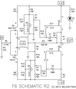
All the input switching, volume control and muting could be done with switches and pots but sonically good volume pots for balanced circuits with really good channel tracking, and motorized for remote control, are expensive and can become noisier as they age, and it is just not an elegant solution. I looked around at what had already been done on the market and I own a Nelson Pass Aleph P preamp which had very neutral sound so I decided to go with a similar design for the control board, but where Pass Labs used a microprocessor I would use discrete digital chips. The idea behind using discrete digital chips is: no programming required, easy to trouble shoot, and no digital electrical switching noise to affect the sound when the control buttons are not being pushed. Any onboard oscillators could be isolated from the audio side of the board and decoupled to prevent noise in the audio.
In all designs there are decisions to be made and this one included several but one was the question of where along the signal path to put the attenuator, before the preamp gain circuit or after. I have seen it both ways and seen arguments for both. Putting the attenuator after the preamp moves any items that might add noise until after the amplification so you don’t amplify the noise, the down side is the output resistance to the amplifier will vary with the volume setting. After looking at the thermal noise specs of resistors used in audiophile designs I decided it was a very small concern. Another downside was the power dissipation in the resistors at the output side, audio signal already amplified now needing attenuation, but the voltages and currents are small so that doesn’t pose a real problem. Putting the volume control before the preamp meant having the preamp gain buffer closer to the output and able to drive interconnect cables better, so that is how this board is designed. This control board is for fully balanced audio, input to output, for four of the six inputs. It can be used single ended for all inputs by connecting the negative input to ground input pin. The two inputs which are single ended can be modified on the board to full balanced with four cuts and direct wiring as they are only single ended by a ground line added to one side of the relay.
I began with the volume control section. The first design decision is how many bit, four bits is easy to display but only gives 16 volume level steps, too few, eight bits give 256 volume level steps, more bits is not as easy to implement for displaying the volume level but gives sub-DB per step, so eight bits were chosen.You need one button for Up and one for Down, which needs to be de-bounced. You wouldn’t want to have to push the button 256 times to go from zero to full volume so a helper circuit needs to be added. And finally, you need to step up to 256 and stop so you don’t roll over back to zero, and on the down side you need to stop at zero and not roll over to 256 which could be jarring and potentially destructive to your speakers.
The Input selection circuit was next. How many inputs do you need? I chose to have six inputs controlled by one button, again de-bounced, and scroll one to six and rollover to one again.
It would also be nice to have a mute button so you can silence the system instantly for a phone call, or whatever, and be able to un-mute to the same volume. I like to disconnect the volume control section from the gain section and ground the input to the gain section for absolute quiet while muted.
And finally, a remote control would be extremely nice. Never having worked with infrared or RF transmitter/receivers I studied advantages and disadvantages of each and since it is an indoors system where most audio systems are used, and a short distance, infrared is much simpler and cheaper. With four different signals, volume up and down, mute, and input selection, an encoder and decoder chip set would be necessary. So much for the design decisions, on to the actual design.
Main Board:
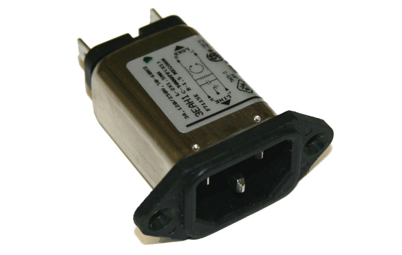
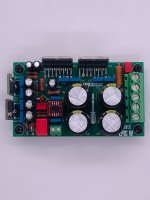
The main board contains the power supply for the control circuitry which consisting of a double primary and double secondary winding transformer, T1. The double primary windings can be paralleled for 115v or used in series for 230v, set with the switch S2 (you can use jumpers if you like to save a dollar). The secondaries are in parallel for the higher current output. The AC voltage and current is rectified by a bridge rectifier, D1, and fed through a fuse to the fixed voltage three pin 5.0 volt regulator, U1. There is a current storage capacitor before the regulator, C1, and one after, C2.
There is a reset controller, U9, that reads the voltage at startup and sends a reset pulse out when the voltage has reached the operating point so the board comes up in a known state: the volume at zero, no input selected and the mute not active. The output pulse of the reset controller is sent through two inverter gates, U12, in series so a positive and a negative going pulse can be directed to the chips which need to be reset with the appropriate polarity pulse.
There is an oscillator made with a 555 timer chip, U5, running at 15 Hz, its output is ANDed by U2 with the volume up and down signals to step the volume up or down while holding a button down on the remote or display board. There is a third input to the AND gates, U2, for the volume up/down inputs which is from the enable/inhibit (E/I) circuit created with U10, U11, U13, and U4, and reads the eight output lines from the 2 counters, U6 and U7. When the output from the two counters reaches maximum volume, 255, the output of the E/I chips is ANDed by U13 and inverted to proper polarity by U4, goes low to the Up AND gate so it will not accept any more input and thus not roll over from maximum to zero. Likewise, when the two counters reach zero the output of the E/I chips, U10 ANDed by U13 and inverted to proper polarity by U4 goes low to the Down AND gate, U2, so it will not accept any more input and not roll over from zero to maximum.
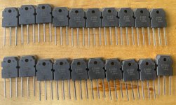
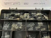
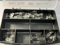
The output from the volume counters is fed to the volume display control circuit, U14 and U18, and the output lines from the counters also drive a transistor per line to turn on a relay to control the volume resistors. The resistors that pass the audio signal were chosen after reading an article in Linear Audio showing the distortion levels in different types of resistors. The Dale/Vishay RN60D resistors were listened to and then used in the design. There are four of each value and are matched to better than 1%.
The volume display control circuit is made up of U12, U14, U15, U16, and U18. Two gates of U12 form an astable oscillator which clocks the counter U14 and the display counters on the display board at 5 kHz, C5 provides the oscillator with a tank and R3 sets the speed of oscillation. U15 and U16 are two 4-bit comparators, ganged to form an 8-bit comparator. This compares the output of the binary counter U14 with the binary output taken from the volume counters U6 and U7. When the comparator inputs are equal, pin 6 of U15 goes high, triggering the monostable U18, which outputs a brief pulse to the latch control line that goes to the display counters on the display board. When the counter U14 reaches a value of 256, the link between pins 11 and 12 resets the chip and sends the reset pulse to the display counters on the display board also.
The input selection signal from the display board is inverted by U4 to drive the counter input of U8s clock; one press of the input selection button clocks the counter up by one. The three output lines are in BCD, and go to a BCD decoder U17, a high current device, which is capable of driving the input selection relays directly. The outputs from the counter are ANDed together so when all three are high, a seven, it outputs a pulse which is inverted by a U4 gate to the correct polarity to clock the Load input of the input selection counter whose inputs are set to load a one. The outputs from the counter also go to the display to be decoded to show the input selected. So, the input counter starts at zero at power up, counts up to 6 and resets to 1 in a loop of 1 to 6 back to 1.
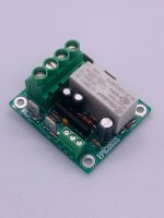
The mute control signal from the display board sets and resets a flip flop, U3, whose output goes to the mute control relay to mute the audio and the output of the flip flop also goes back to the display board to turn on and off the mute LED.
Display Board:
The display board has an infrared photo receiver, PH1, operating at 950nm and 38 kHz modulated signals, capacitor C1 makes sure the receiver has very clean power. It demodulates the signal back to the code sent by the remote, but it is inverted so it is sent to an inverter, U1, then to the decoder chip, U2, which decodes the pulse train input which then raises one of its four output lines for the code received. The outputs are for volume up and down, input selection and mute control. The decoder output is ORed with the user push buttons by U3.The input from the user buttons are “debounced” by a network between the push button and the OR gate. The input to the inverter, more gates of U1, are held high by a pull up resistor, and charges the capacitor, which keeps the inverter output low. When a button is pushed the capacitor is discharged through the resistor in parallel with the diode, when voltage reaches a low enough level the inverter switches to a high output. When the button is released the capacitor is recharged quickly through the diode in parallel with the resistor, at a high enough voltage level the inverter switches to a low output. The inverter is a Schmidt trigger type so it cleans up the input wave form from the user. These control signals go across the ribbon cable to the main control board.
The display board also receives control signals from the main control board over the ribbon cable.
The mute control signal turns on and off the transistor, Q1, which drives the red LED D5, R9 limits the current to the base of the transistor and R10 limits the current to the LED, increasing the value of R10 will reduce the brightness of the LED.
The three control signals for the Input control are BCD, Binary Coded Decimal, and are fed to U4 which decodes the BCD in to signals to drive a 7 segment LED display directly through current limiting resistors (U4 requires a common anode 7 segment LED).
The volume display is driven by three control signals: a 9 kHz clock signal, a latch signal, and a reset signal. The counter/display driver chips, U5 – U7, each drive a 7 segment LED display directly through current limiting resistors (U5 –U7 requires a common cathode 7 segment LED). The counters are daisy chained so that the first counter U7, or ones place digit driver, is fed the 9 kHz signal to its clock input, when it reached its maximum count it outputs a clock pulse from its carry output to U6 clock input, when U6 reaches maximum count it outputs a clock pulse from its carry output to U5 clock input. The count of the counter is not displayed until the latch control signal on each counter is pulsed by the common latch signal, the counter then outputs the decoded count to drive the LED segments. When the maximum count is reached the reset line is pulsed by the main board resetting the count to zero. The latch signal refreshes the display approximately 9 times per second. Whatever count is latched remains on the display.
Prototyping designs:
For a visual display of the volume level I started with eight LEDs, five green, two yellow and 1 red LED in a line to display the volume as binary data, it looked neat to an engineer but not really good for a consumer product so seven segment LED displays were chosen, and to display 256 requires three. To drive the display for eight bits would require a dedicated circuit as only 4 bit display drivers existed. I looked around for an idea on the web and found a circuit that looked interesting and when tried it worked but required some debugging. (This is a more detailed explanation of the info above). The circuit, most of it on the main board, uses two 4 bit comparators, U15 and U16, tied to the outputs of the counters, U6 and U7, and compares with the output from another free running counter, U14, driven by a nine kilohertz oscillator, U12, which would update the display 9 times per second and which also clocks the counter/display driverchips, U5 – U7, on the display board. When the counter output, U14, matches the volume control output, U6 and U7, it triggers a mono-stable one-shot, U18, which pulses and latches the count on the display drivers, U5 – U7, on the display board. It worked but the display would flicker at certain volume counts due to a race condition between the volume output lines and the free running counter, one moment it would display one number below the volume number and the next moment the actual number. A different resistor value on the mono-stable one-shot pullup resistor, R4, was needed to makethe circuit more stable, then on the second revision a capacitor, C7, to ground on the one-shot input circuit was needed to stretch the latch pulse long enough to stop the flickering.
The Input selection circuit was next. It also would use a binary up/down counter, U8, but only one button input to count up 1 through 6, when it hits 7 an AND gate enables and resets the counter, which is set to load a one into the register so it starts at one again. The output from the counter goes to a Binary to Decimal Decoder, BCD, U7 on the main board, which drives the input relays directly, (hicurrent output). The lines from the counter also go to the display driver and another seven segment LED display.
The mute circuit uses a flip-flop, U3, that toggle between on and off to drive a relay that disconnects the volume section from the preamp and grounds the input to the preamp to remove any possible noise on the output. It also drives an LED as a visual display.
All was coming together but testing showed an issue with the circuit coming up in random states on power up so a reset chip, U9, that sends out a reset pulse at power on is used to reset everything to a known state.
The last thing needed was to design a remote control. Linx Technologies makes a couple of sets of encoders and decoders chips as well as RF remotes in key FOB cases and RF receivers but after pricing RF antennas and cables I decided on infrared as the way to go, read less expensive. For a receiver I tried a phototransistor but ended up with a TSOP 38 kHz IR receiver and since it was most sensitive at 940 nm wavelength an IR LED was chosen at that wavelength for the transmitter but the output of the encoder had to be modulated with a 7555 timer to the 38-kHz carrier frequency so the IR receiver could pick it up. Since I had never worked with IR LEDs I did a lot of testing but I am still not 100% positive that I am not overdriving the transistor driving the IR LED. Different TSOP IR receivers were tried as they have automatic gain control, AGC, built into make them less sensitive to a noisy environment such as strong fluorescent lighting, but too much gain control and you can lose data so an AGC2 chip worked best in testing. The receivers are also made for short burst data and long burst. The output of the encoder could be considered long burst so that left two part number options in the TSOP receiver and either worked well.
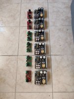
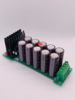
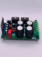
The power supply for the controls needed to be 5 volts for the logic chips and relays. After estimating the worst-case current for all the chips and relays it might need 3 amps so I found a 6.3 volt transformer with 5 amps capability, passed through a bridge rectifier, a capacitor, then a 5 volt fixed regulator for three amps then another storage capacitor. When all was done I found the average current drawn was under one amp, for 5 watts of power on the board. The first revision of five circuit boards used the larger, heavier, more expensive transformer, the next revision used a more appropriately sized transformer and bridge rectifier.
Remote Control:
The remote uses a four-input encoder chip to encode the four user buttons: volume up and down, Input selection and mute. The encoder chip stays in low power mode until one of the user buttons are pushed taking that line high, the encoder outputs a code for as long as the button is held. The output of the encoder is tied to the reset pin of a CMOS version of the 555 timer. A high bit from the encoder turns on the timer which outputs a square wave of approximately 50 percent duty cycle at modulated 38 kHz, set by C2, R5 and R6. The output of the timer drives the base of a transistor which turns on and off the infrared LED which operates at 950nm wavelength. Resistors R1-R4 keep the inputs to the decoder low until a button is pressed. Resistors R7 and R8 are used to limit current and R9 develops a voltage across it to bias on the transistor a little quicker. Capacitor C1 is current storage buffer for the timer though it may not be needed on the CMOS version of the 555.
Capturing the Schematic and laying out the PCB:
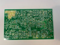
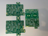
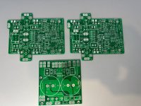
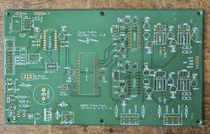
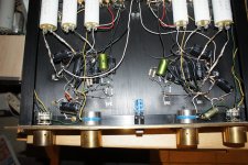
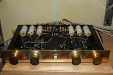
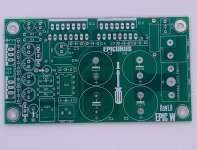
The next step in the design effort, after testing and debugging bread boarded circuits, was to draw the schematic in a software package to layout a printed circuit board. I found a free trial version of a nice package from DipTrace but the schematic grew beyond the free version of the software so I purchased a version that could handle 400 nodes. There was a learning curve on using the software but patience had a full schematic for a main board, a display board and a remote controller schematic done with time. After determining the space available in the preamp chassis, 7” x 12”, and the rear panel layout of the connectors and the front panel, 6” x 1.75”, for the display and control buttons I started the main board layout. The software places all the parts on the board but you have to drag them around to their optimal positions. You then run the automated router which turns the schematic lines to traces. Keeping the digital traces away from the analog and changing audio signal traces to extra wide kept me busy drag traces around and rerouting traces for quite a while. It seems that laying out a printed circuit board is as much art as it is engineering skill, there are many things to check on and make sure nothing is missed. After everything is double checked with a full sized printout of the circuit board, I then had a board house turn out five high quality sets of circuit boards.
Building up one set of boards went quickly and amazingly it came up and worked but with a few issues. I found the first problem of the input selection relays on the board were mirrored in the layout so they had to be placed on the bottom of the board so they worked correctly (corrected in version 2). The display flicker was solved by the afore mentioned capacitor on the display latch chip. Another problem took a little longer to find, when the input selection button was pressed the mute circuit would activate. The problem was finally found in the ribbon cable from the display board to the main board where the routing software had the two lines side by side in the ribbon cable. I knew that digital signals are supposed to be separated with alternate lines being ground lines but forgot to check for that (Also fixed on version 2). Then I removed the fuse and measured the current draw of the board this is when I found it needed less than one amp of current so a much smaller, less expensive, transformer could be used (another change in version 2 PCBs). A second version of the circuit board had all the bugs worked out but I forgot the display flicker Capacitor but that was easy to solder to the backside of the circuit board.
One thing to be careful of when assembling the display board is the seven segment displays are different for the volume and input display one is common anode and the other is common cathode, don’t get them mixed up. As with any build, carefully observe the polarity of diodes, LEDs, capacitors, transistors, and logic chips when inserting them in to the circuit board.
So how does it sound? I thought it to be very transparent, neutral, but not trusting my own ears since I, as the designer, might be biased I had my audiophile business owner listen to it and he thought it to be very transparent also, which is really the best you can wish for in the control system.
The Bill of Material, BOM, spreadsheet gives component reference designations, manufacturer part numbers, Mouse and Digikey part numbers, and my preferred vendor for each part since pricing can be different or a part not available for one vendor. The pricing used for the total price is for buying some of the parts in volume. If you buy PCBs in Lots of 100 you can get the price in the BOM but you also must pay a $150 per board design NRE charge, about $1.50 per board on the original order of version 2 boards. I don’t even want to remember the price on the original version 1 boards at five pieces each plus the NRE charges. I can supply gerbers and the drill file if anyone wants to turn their own boards but to make things easier and less expensive over all, my audio business friend said he could supply sets of PCBs from his stock for $120, it covers material costs and shipping. I also have five of the version 1 boards with the bigger power supply, built and tested, for $400 per set, includes the remote control.
You can use this controller in your personal preamp, and I don’t even mind if you want to use it in a commercial design, I just ask that if you make any improvements you feed that back to the group so we all can benefit. Hint: the first thing I would change is the transistor in the remote, instead using a FET for lower standby losses. (Note: This was fixed in Remote version R2c) So the only other thing that could change is I ever turn the Main board is updating the one-shot U18 kluge design to a real one-shot chip, although it works fine as is.
Updates: ************************
Since the first posting it was discovered that the Linx Tech LS series Encoder and Decoder chips have been discontinued. In the later posts there is new schematics, gerbers and BOM for the later Revisions of the Remote and display board with the new Linx Tech Encoder/Decoder chip. All Board Gerbers and Schematics are in post 150, The last version for the V5 main board are in post 179, schematics are in post 165 are not recommended as the one shot timing is too finicky and the volume display can flicker.
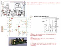
Since the first design of the volume board used paralleling resistors in a digitally weighted design, it was found that the input resistance would drop to 162 ohms, loading most sources too much, so the resistors were changed so the load only dropped to 300 ohms. The best values were 20K, 10K, 5K, 2.5k, 1.25k, 625R, 312R 156R.
***********************************
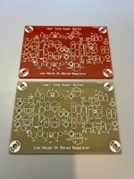
So the design started to morph, instead of a set of push buttons for volume up and down someone wanted a rotary encoder so that started at new project. Then a ladder resistor scheme which has either a constant input or output impedance was looked at and I chose a 10k input impedance. So starting at post 225 the design started to take shape. It has a power supply board, a Digital board, a Display board, an Analog board, and a remote controller board. The first design was done with only logic chips, to clean this design up a bit I used an EEPROM to hold data for the display on this design. Sonically the first listening tests were excellent so I proceeded to work the bugs out and improve the design with forum input.
The latest of the second design are:
Schematics - Post 280
Faceplate CAD - Post 282
EEPROM Data File - Post 282
Digital Board 3.0 - Post 278
Display board 3.1 - Post 352
Power Supply board 1.1 - Post 326
Analog board 1.3 - Post 326
Remote Board 2.0c - Post 150
BOM 3.1 - Post 330
Build Instructions - Post 287


