3 Way Bullet Build - Official epic awesome office build thread

I think I'm about 3 months into this project so far but I'm now going to start the build thread.

This build consists of 3 way nearfield monitors and a coffee table that is also a push-push bass reflex subwoofer.

This is in no way an "optimal" build. It was never supposed to be. It is meant to be an outlandish, exotic, fun build. I wanted to use different drivers, different configurations, different methods, different everything. I can build a two studio monitor and have it play back accurate. This is not that. That I could just buy. This is building something you cannot just buy. Something you'd have to make. Something you'd have to explain to even someone into audio.

OBJECTIVE:
Create an awesome 3 way setup with a sub that goes from 18 hz to 40K hz. Distorion under 2% for everything 200 hz and up. It needed it fit under my triple monitors and not take up too much office space. By making the coffee table for my office couch the sub I have succeeded for the sub. The 3 ways are pretty big but they tuck under the monitors which is dead space anyways. Budget was under $500. I think I might end up a little over with the crossover but we will see
Monitors:
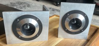
Tweeter
- GRS RT1.R - 5K hz and up $60 (on sale)
I hear good things about these ribbons. This is the first time I am using a ribbon tweeter. Hoping there isn't too steep of a learning curve. I took the measurements with a 45 uf cap. The sweep sounds insanely clean.

MID: - GRS 8" Mid Planar - 800-5k hz $55 (on sale)
This is another first, I have never used anything other than a cone driver for a mid so far. I did spent a ridiculous amount of time 3d printing horns. I learned a lot. I can get it go down to 500 hz cleanly but it requires a massive horn and that isn't the direction I wanted to go.

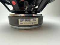
WOOFER: - Epique 5.5" MMAG Woofer $70 (on sale with coupon)
I was hesistant to go with this driver. It has measured out very well. With the port its hitting down into the 30s with ease. Impressive little thing. I got it on sale so not so bad. It has an incredible amount of XMAX. Interested to start working with this thing


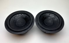
Subwoofer: - GRS 12" High Excursion Paper Cone
Nothing special here. I have simulated these before and wondered how anyone could have a use for them since they require such a large box. Well, a coffee table is around 13000 inch square. So two of them work perfectly here.
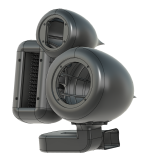
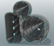
ENCLOSURE:
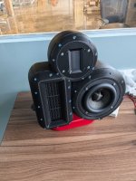
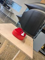
This is a 3d printed enclosure. The filament used here is carbon fiber infused PETG. It is dense, heavy, and rings super low. I have so much bracing in this unit and the walls are so thick I'm pretty sure I could park my Acura RSX on it without it failing. I'll throw up some pictures for you to see. This part was printed on a very large 3d printer and it took 3 days to print. In total it is 6 pounds of filament. This isn't your friends 3d printing. This is industrial grade. I have a few of these at work and use them all the time. This required the largest one we have.

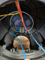
The Planar Mid is sandwiched inside the enclosure between the face and the body. Behind the mid planar is a diffusion array. I tested a bunch of these. This one works the best by a long shot. Not exactly sure why. The back cup is filled with polyfill. There is a sheet of microfiber cloth between the fill and the planar so the poly fill fibers do not end up inside of the driver.

The enclosure is exactly 0.38' cube. I forget how long the port is but it is exact to what I wanted. Do not underestimate the amount of time it took me to create this model to EXACTLY 0.38' cube volume AND have the port the exact length. The port is the stand. It still in prototype stage but with eventually be 3d printed in the same black filament as the body.


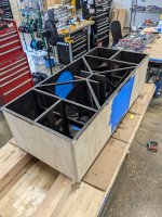
Coffee Table Subwoofer:

So this became of me just screwing around one night with WINISD. I needed a coffee table and didn't want a boring one. I run the fab shop of an engineering consulting company so I figured I might was well make the coffee table a sub and show off some fab skills. The volume is 13000" square. I forget the port length but there are two of them and they are 4" diameter. That is as wide of diameter as I could go without adding bends which I didn't want to do. They fire at the floor. The table will be 2" off of the floor. I won't get past the max port velocity until 200 watts so I think I am ok. I'll be powering it with a 200 watt RMS amplifier. I will run them in series for an 8 ohm impedence. This is an office so that should be sufficient. I'm not trying to shake the building down here.

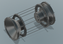
The woofers will be sandwiched between the middle bracing and the outer walls. They are more than snug. I already fitted that up. They will not be screwed to the sides. There will be 8 M5 threaded rods running through the entirety of the cabinet to link the two woofers. There are also some reinforcing rings midway so that the threaded rod doesn't try to bow as they run a decent distance.

I think the bracing is sufficient if not a little overboard. Again, I can probably park my Acura on this without it breaking.

The big party trick here is the top will be clear Acrylic. It will be screwed on with gasket on all the bracing to seal it. No way am I doing all this crazy engineering and then hiding it. Nope, I want everyone to see what is going on.
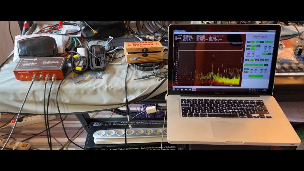
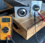
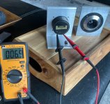

Measurements:

These will be coming soon. I just took them today. I will get them into VituixCAD and start messing with the crossover. I'll probably go with a 3 way series crossover. I like the flexibility of the series crossover. Less need for a bunch of components in the form of notch filters. The Mid planar and the Ribbon will both require some notches. I can already tell from the measurements. They do all measure very clean. These are much lower distortion drivers than anything I have used before. Anyways, coming soon, I am running out of time before I have to head out to dinner.


Thanks for reading. I should be done with the sub next week and the crossover within the next 2 weeks.

Attachments

  • PXL_20241228_205117938.jpg
    PXL_20241228_205117938.jpg
    452.1 KB · Views: 351
  • PXL_20241228_205126020.jpg
    PXL_20241228_205126020.jpg
    400 KB · Views: 311
  • 1000006017.jpg
    1000006017.jpg
    437.9 KB · Views: 279
  • PXL_20241228_154029416.jpg
    PXL_20241228_154029416.jpg
    524.8 KB · Views: 277
  • PXL_20241228_143957886.jpg
    PXL_20241228_143957886.jpg
    674.3 KB · Views: 287
  • PXL_20241228_143959632.jpg
    PXL_20241228_143959632.jpg
    686.1 KB · Views: 294
  • PXL_20241228_205119786.jpg
    PXL_20241228_205119786.jpg
    406.7 KB · Views: 304
  • PXL_20241228_163426459.jpg
    PXL_20241228_163426459.jpg
    555.6 KB · Views: 334
  • Screenshot 2024-12-28 162141.png
    Screenshot 2024-12-28 162141.png
    547.6 KB · Views: 307
  • Screenshot 2024-12-28 162120.png
    Screenshot 2024-12-28 162120.png
    1,009.1 KB · Views: 310
  • Screenshot 2024-12-28 165647.png
    Screenshot 2024-12-28 165647.png
    850.6 KB · Views: 316
  • Screenshot 2024-12-28 165624.png
    Screenshot 2024-12-28 165624.png
    1.2 MB · Views: 348

ASTM New Diffusion Standard - ANDS

This is going to be a bit of a dive into acoustic diffusion, so fasten your nerd spectacles with enough duct tape, Let's go to acoustic space!

I'd like to present diffusion from the point of product photography to give a visual reference point of what diffusion and reflections are, so it can be a bit easier to understand the concepts. Photos 1-4 are from the book Light - Science and magic, An introduction to photographic lighting, 4th edition, pages 35-37 (F. Hunter, S. Biver, P. Fuqua, published by Elsevier inc. 2012)
1000013597.jpg
1000013598.jpg
1000013599.jpg
1000013600.jpg


The Phase and amplitude balloon graphs of an acoustic diffuser (phase grating panel), measured with the proposed ASTM New Diffusion Standard @ 8.5kHz show the same effect as diffusing material (white paper/phase balloon) and specular reflection (plastic handles of the soldering iron & pliers, all metal parts/ amplitude balloon)

Tuote HiPer PanelGLL 8.5khz phase shift.jpg

Tuote HiPer PanelGLL 8.5khz Attenuation.jpg

This is the measured panel on the balloon graphs above. Being a flat panel, it produces a specular reflection but the holes affect the phase change ie. light reflecting off of a white paper.
Tuote HiPer Panel.jpg

Several measured diffusers, the .GLL files and GLLViewer can be downloaded from NWAA Labs https://www.nwaalabs.com/Index Surface Reflectors (Diffusers).html

This article explains the flaws of measuring acoustic diffusion and trying to depict the phenomena with a scattering coefficient on a simple graph with the current standard:
October 9, 2022
The Misunderstanding of Acoustic Diffusion Test Data
Where we've been, where we are and where we're going
Richard L. Lenz, RealAcoustix LLC.
https://realacoustix.com/news/news-full-article/tmp-1

Matthew Poes of Poes Acoustics has a ~5min part in his video from this topic
Login to view embedded media
This mammoth of a video goes deeper into this topic, with explanations and measurements straight from physicist/acoustician Ron Sauro (NWAA Labs) and acoustic designer John Brandt, hosted by Karthik Ramanathan. Timestamp starts from the similar phase grating panel pictured above and continues to a show examples of diffraction modules.
Login to view embedded media
Didn't find much conversation about these topics so I hope this helps and opens up some discussion about the possibilities these new measuring methods can provide to modifying our acoustic spaces, but also how these may be utilised in speaker design. And please do correct me if I'm way off on something, I'm only a novice on acoustics and as english is not my native language there is a bit of a language barrier.

For Sale 2 Pairs Of Unmatched Yamaha 2SJ26 2SK76 V-FETs

Up for offer are 2 pairs of NOS unmatched Yamaha 2SK76/2SJ26 V-FET's. I got these years ago from someone that Yamaha supplied samples to for an audio mag V-FET amp article they were writing back in the day. Since I haven't done anything with them yet it's time for someone else to hopefully make them do what they do best and enjoy them.

How about $180 US for the set + shipping and duties/tariffs for these sonic beauties.

1742145374871.png


Sorry but NA shipping only.

SAA 7220

Hi all! So there is an old thread on this Chip. That it is very power hungry and noisy

And the thread poster wanted to have a dedicated PSU. Although I’m not sure why they talked about grounding it… if I understand it right. Isn’t the right way to do it is to have a PSU that have 5 volt to VDD and VSS ? And leave it grounded in the board.

The data sheet shows Pin 12 and 24 wouldn’t that solve the power issue ?

Is there someone out here that have experience in this!? 🙏

Hello, i am noob audio engineer

Hello, I am noob audio engineer from South Korea. My father was audio engineer and professor in 70s.and now I got his heritage(I used the word 'heritage' because he is too old to continue making amp because he can barely see. He is healthy) I have his 6v6 pp amp and other tr amps. Especially the 6v6 pp amp was his last work as he retired as a engineer and professor.(look at the pic) It had wonderful sound. But it is too old, it keeps causing problems. I don't want anyone to fix my father's work. So I want to study audio on my own and fix it(it is still not working)and also make my own amp too. Now I am making 6aq5 se amp for study. But I need advice from anyone here, so I joined the forum
1742225564050.jpg
  • Like
Reactions: anatech

Coax / tapped horn speaker

Howdy. Wondering if anyone has considered a 4-driver PM90 with some of the new B&C coax drivers? I was thinking one could probably achieve a high-SPL box that's still pole-mounted. I was looking at B&C 8NDL64 drivers, which are less than 6lbs each. Add that to the B&C DCX-464 and either their ME464 horn or the RCF HF950 and you'd have a Loud full-range speaker.

I've been looking at the Meyer X40, Peter's PM90, and the Danley SM100B. Danley uses four less powerful drivers to keep up with the 5" coax mid/high. Peter has two horn-loaded drivers. Meyer just has two angled front-loaded drivers with a slotted port on the X40 and two slots on their larger X80.

I was thinking that Peter's design with the B&C horn would leave room for a pair of 8" drivers at top and bottom. Total component weight plus the horn comes out to less than 45lbs with crossover.

Thoughts? Anyone wanna throw this into some software and take a look? I'm an ideas guy - no idea how to run hornresp or any of the other fun toys.

Can this phono preamp produce these measurements? They are more than good! But are they true?

Dual DC power supply from + 9 v to +18 v and - 9 v to -18 v, alternatively single power supply from +9 v to + 28 v DC (on customer request).
Input sensitivity 3 mv out 1470 mv gain 50 db, signal to noise ratio 105 db, impedance 47 Khom. frequency response 15 HZ 30 KHZ.


s-l1600 (1).jpg
  • Like
Reactions: lineup

Commercial Projector Ballast Bypass Guide

The ballast was pretty easy to bypass after some poking around with a multimeter.

***For those of you that are having trouble bypassing the ballast on any projector***

1 - Find the group of wires that come from the ballast to the main board.
2 - Power the projector on with NO lamp.
3 - Measure the voltages on all the wires connecting to the main board.
4 - Find the wire that is close to +3V
5 - Insert lamp (If you have one) and power on. Measure the voltage of this wire again. The voltage should be around 0V
6 - Connect the spot on the board where that wire connected to a ground on the main board.

This will bypass the lamps for 90% of projectors. It has worked for me on about 8 different models. All else fails just ground each wire and power on and see if the projector stays on. Remember that the wires coming from the board need to be grounded NOT the wires coming from the ballast.

This seems to be a frequent question/problem. Maybe this can be made into a sticky since commercial modding is getting popular.

"The Bog Standard" - A good enough amplifier for the rest of us

Well... Here goes nothing!

I've been reluctant to do this out of fear of ridicule. You see, I'm not a very experienced designer and the design I'm about to present is a pretty mundane Class AB job.

But lately I've seen beginners on various forums struggle with designs that require exotic and/or obsolete components or designs that require very stable power supplies and careful thermal management. I've also seen people having a tough time with what's clearly outdated or outright bad designs that are floating around. So based on that, I thought a fellow beginner might find this thread useful.

I decided to share a decent amplifier that can be built using cheap components that are readily available from almost any source. It uses only 2N5551/5401, BD139 and IRFP(9)240 transistors, some 1N4148 diodes, a couple of 5V zeners and a smattering of capacitors and resistors. That's it! It runs fairly cool, does fantastic with a modest 40mA bias current and has a net negative temperature coefficient with regard to bias if you're careful with the thermal transfer between the VBE multiplier and the output MOSFETs. It physical tests, it's fairly flat past 100kHz at 50% power and gets a decent 0.003% THD at 80% power and 1kHz in simulations. I don't have the equipment to measure an accurate physical THD, but just eyeballing it on the scope, it's definitely <0.1% and probably a lot less. Nothing compared to the Class A masterpieces some people here are building, but enough to sound pretty nice. The way it's drawn it should be good up to 50W with the right heatsink.

It's also very forgiving in terms of component values and (probably) layout. I've messed around in SPICE, and it takes real work to make it misbehave. You can even mess up the matching of the LTP transistors quite badly without it throwing a fit. It also has a >70 degree phase margin in simulations and would probably do fine with a lower Miller capacitance if someone wants faster performance. I've tried it with 8ohm and 6ohm speakers, and based on simulations it should have no problem at all with 4ohm as long as you're staying within a reasonable power (50W). The gain is 23x (27dB), which is a bit low for regular line level. You could probably bump it up a bit, but I'd probably recommend a pre-amp instead. I haven't checked the stability with a higher gain.

This design has been built and sounds and measures well. Audiophile quality? Probably not, but good enough to "open up" music I've listened to many times before and letting me discover new details.

I'll share the schematic and also a Github repo with all the design and simulation files, along with some ideas on how to build and test it. If you're a beginner, feel free to try it or just borrow ideas and inspiration. And if you're an experienced designer, I'm happy to listen to ideas for improvement. You can even clone the repo and send me a pull request if you want to contribute. But please be gentle! 🙂

There are a few things I'd like to change when I get a chance. The pot on the long tail can be replaced with fixed resistors and the terminal block for the speakers on the middle of the board is awkward. But it's buildable and works well in its current form. You could (and probably should) add speaker protection and maybe a preamp and some tone controls.

The repo: https://github.com/prydin/classab-amp-mosfet

I hope you'll find my humble contribution valuable in some way. And be gentle on me!

[EDIT: Updated the schematic with a protection diode for the VAS to avoid disasters... Also removed the DC offset pot, since it doesn't do much due to the current mirror]

1737820163866.png

NAD C355 adjust procedure

Good morning.
I have a NAD C355bee amplifier, which actually works very well and sounds great.
However, just out of curiosity, since the amplifier is already 15 years old, I tried to measure the Idle current and isc circuit parameters.
In the service manual it refers to a value of 6mV for idle current, however, I measured a value of 8mV (after the amplifier had been on for 20 minutes), in both channels (to be precise 8mV L channel and 8.1mV R channel).
Can these values still be considered normal or do they need calibration as reported in the manual (6mV)?

For the calibration of the ISC circuit I did not understand well how to proceed.
The manual indicates "adjust the pot VR3 to make the DC voltage of the point of TP10 to the same as TP11".
If I measure TP10 (one tip on TP10 and one on ground) I get 56.5mV
If I measure TP11 (one tip on TP11 and one on ground) I get 19.5mV
If I measure TP10 + TP11 (one tip on TP10 and one on TP11) I get 34.7.

1000018722.jpg

1000018726.jpg

1000018728.jpg

I have not touched any potentiometers yet, and before I do (if necessary), I would like to understand..

Thanks very much!

HDI-3600 Crossover Upgrade - JBL with Mundorf

Hi guys, I have a new-to-me pair of HDI-3600 and would like to turn a great pair of speakers into a super pair of speakers. Having a look at the stock crossovers, lots of room for improvement, I think JBL could have done a better job frankly given the cost of these - no-name electrolytics (par for the course) and no-name film which appear entry level in the HF.
Question is, moving these caps and resistors to Mundorf options leave me with small variances in values.

I am not thinking these variances would make any significant difference, but interested in folks’ opinions. Would these small differences add up, what about the resistors?

Here is what I am looking at - replacement value + originating value for both caps and resistors:

Product+value_________________Original Value_________________Application

MCap Supreme
1.8uF(600V) _ _ ___________________ 1.8uF__________________________HF

MCap Supreme
3.9uF(600V) _______________________ 4uF___________________________HF

MCap EVO
22.0uF(450V)______________________ 24uF__________________________HF

MCap MKP (250V)
15.0uF(250V) ______________________15uF__________________________LF

MCap MKP (250V)
22.0uF(250V)_______________________23uF__________________________LF

MCap EVO
6.8uF(450V) ____________________6.2 & 6.8 uF___________________HF & LF

MCap EVO
15.0uF(450V )_______________________14uF_________________________HF

MR10 Metal-Oxide Film Resistor
2.2Ohm_________________________10W2R4J________________________HF

MR10 Metal-Oxide Film Resistor
3.9 ______________________________10W4R3J________________________HF

MRES20 MResist Supreme Resistor
10Ohm _________________________25W10RJ________________________ HF

Any thoughts or wisdom from experience? Notice I am considering vanilla MKP on LF and Supreme/EVOs on HF..

Thanks!

AM/FM Stereo Synthesizer Tuner Fisher T-2421 (or FM-2421)

Hello, I have got this Fisher AM/FM Stereo Synthesizer tuner from around 1980 for many years now. At some point long ago it started to produce audible distortion with all Stereo stations, independent of signal strength. It works fine if switched to Mono mode and all functions are OK, like auto tuning, store, mute and LED's. Because of the slow increase in distortion over time I think it must be a (typical?) component loosing or changeing its value. I noticed an identical problem on other vintage tuners too.
The stereo containing frequency seems to be one or two digits away from the maximum strength frequency. Like I get a stereo light at 91.00 and maximum undistorted Mono at 90.20

Does anyone have an idea what to look for? I have found no service manual, so I did not open it yet. I dislike turning anything inside without a plan. I got a scope and all the usual stuff for electronics, but I'm kind of fixed on amps, my knowledge of tuners is very near to zero. Next I would mark the positions of the adjustable coils and watch for any change turning them a little, but that will be a last try before disposing it.
Would be great to get some hint what to look for and a pointer to a service manual.

Thank you.

Stripped-Down Current Dumping

I have designed couple current dumping amps. They have a common problem, too complicated. I never had the courage to actually build one.

I hope this my last attempt. I minimize all the unimportant parts and meanwhile retain the performance.

It has couple features that the original Quad 405 does not have.
1. Include the transistor Q2 in the opamp negative feedback. It creates a "super transistor" that has almost 0 impedance at the emitter.
2. I move all the gain to the output stage, The opamp works at unity gain. It simplifies the circuitry around the opamp. Also you can get most of performance out of the opamp. As you can see, I got 0.002% THD with LM358. It could be lower if switching to better one.

I leave the final stage 0 biased. I feel it isn't worth the effort to bias the final stage just to get the thd down to 0.001%.

1735861281545.png


1735861444291.png


Edit: 01/02/2025, overhaul the design.

Advantages of Series Crossover vs Parallel for Subs & Open Baffle

A rarely discussed crossover is the Series Crossover (in contrast to the universally popular Parallel Crossover). It offers considerable advantages especially with a subwoofer and a bass midrange. I used a series passive crossover in the Bitches Brew Live Edge Dipoles (which are featured in the new October 2023 issue of AudioXpress). Here is the schematic:

bitches brew series crossover filter slopes.png


ABOVE: In a series crossover, you wire the woofer and midrange in series. You short the woofer with a capacitor. You short the midrange with an inductor.

The circuit above is what I used in the Bitches Brew design. The Bitches Brew has (2) SB Acoustics 15OB350 subwoofers and (1) B&C 15CXN88 coax used as a bass midrange. Note the reverse polarity of the midrange; usually but not always required.

This is in contrast to the usual, BELOW, where the woofer is in series with an inductor and the midrange in series with a capacitor (and both sections in parallel).

bitches brew parallel standard crossover.png


ABOVE: Look closely because this is super interesting.

I'm showing the woofer half of the coax. I'm using actual measured impedance of the drivers in my model, and showing the filter voltage at the driver terminals. The parallel circuit above is not "optimized" for anything except to illustrate the problems with standard parallel crossovers. It just happens to have the same values I used in the series circuit.

In the subwoofer section, the inductor interacts with the impedance of the 15OB350s to create a peak around 50Hz. Then it rolls off above 100Hz.

In the midrange section, the capacitor interacts with the impedance of the 15CXN88s to create a dip at 100Hz, followed by a 6dB peak at 35Hz. Very bad!!! This +5.5dB peak at 35Hz is HIGHLY undesirable and happens ALL THE TIME in subwoofer-mid passive xovers. The reactance of the capacitor cancels the inductance of the bass-mid just below the bass-mid resonance and creates a peak exactly where you least want it.

(The average speaker designer is likely not aware that a passive crossover can BOOST, rather than cut the voltage below the crossover frequency! I discuss this phenomenon in detail in the thread Open Baffle Bass Boost: +4 to +7dB w/ Passive Xover, No DSP where I show some cool ways to use this to your advantage. Especially in dipoles.)

Usually, nobody aware it is even going on. You build a 100Hz crossover for your subwoofer and satellite and you don't even know the satellites are getting a few dB EXTRA bass at, say, 60Hz. Right where it's most harmful.

There is no easy fix for this in a conventional parallel crossover.

However in a series crossover all of the impedance peaks work in your favor instead of against you.

bitches brew series crossover filter slopes close-up.png


#1: The impedance peak of the subwoofer cuts the signal received by the bass-mid by over 20dB at 28Hz. Which is exactly where we most want to protect it. Don't forget, this is 'just a 6dB per octave crossover' yet the electrical slope between 60Hz and 30Hz is closer to 24dB per octave (!) which is fantastic. It's effectively a steep 18dB shelf filter.

#2: The impedance peak of the bass-midrange (which is about 60Hz) interacts with the crossover to boost response 3dB. While this is not desirable per se, the roll off above that point is immediate. In my opinion, the mild 6dB/octave slope above 100Hz helps the subs blend better with the mids.

I corrected the peak at 60Hz with DSP. In most bass-mid crossovers, the midrange would have a higher resonant frequency than 60Hz and would be even easier to work with.

bitches brew series crossover impedance.png

Above: Impedance of the circuit. In this design the 60Hz 2ohm minimum is OK for me. It's possible to choose different crossover values to achieve a higher Zminimum. Actual measurement is below (I've added a Zobel to flatten the impedance.)

bitches brew woofer section impedance.png

In an earlier discussion with @Lynn Olson we discussed the difficulty of getting subwoofers and bass-mids to seamlessly integrate. This is a very good way to do it especially because the cone sizes are all the same. In this design, both subs and bass-mid are 15" and both in the same dipole array.

bitches_brew_2887+s.jpg

The Bitches Brews are bi-amped with DSP, with the active crossover between the coax midrange and tweeter. I could have triamped them, but I felt that a series crossover as shown here was much more simple and elegant. Fewer amps, fewer DSP channels, fewer signal cables and speaker cables.

I feel air core inductors are worth the extra money for an "ultimate" no compromise design like this; I didn't want the hysteresis of iron core inductors. So I used Madisound air core copper foil inductors with DCR below 0.6 ohm (low DCR is very important, the higher the DCR the less attenuation of low frequencies that you get in the midrange signal).

That's especially important in this design, because the DSP boosts low bass 12-15dB around 30Hz and the deep notch in the midrange filter is very desirable there. I can shove hundreds of watts at 30Hz into these, and the midrange cone only moves +/- 1mm or 2mm.

The Bitches Brew has one of the most seamless crossovers I've ever heard. The acoustic crossover between subs and mids is at about 90Hz, all the cones are 13" in diameter, and the coax tweeter integrates perfectly with the midrange. The radiation pattern is extremely well behaved and there are no lobing problems at any frequency.

bitches+brew_polar_150-20K_15dBrange_+-90_third-oct.jpg

Above: Measured polar response, +/-90 degrees, 1/3 octave. I don't have a good way to measure these at low frequencies, but VituixCad calculations are below.

bitches brew vertical directivity.png

Above: VituixCad vertical directivity calculations for 2x 15OB350 and 1x 15CXN88. Variation is only about +/-2dB.

Expanded details on the Bitches Brew crossover are here. @Yourmando

subwoofer enclosure Focal

I have an old Focal 11v7601db element, which I was thinking of building a box for, I found a program online to calculate the box size (42.92 liters Vent diameter 5cm lenght 16.97 ) can it be correct?

Fs :25,57HzMms :108,09gg
Re :2,60ΩCms :3,6E-04m/N
Qes :0,40Bl :10,62 N/AN/A
Qms :12,89Vas :54,84l
Qts :0,39No :85,4 dBdB/W/m
D :20,50cmSd :330,06cm2
Inductance :2.09mHXmax :8,0mm

Gallien Krueger 2000 CPL

Novice here. Looking into 80s rack preamp GK 2000 CPL. It has a single input, 2 switchable channels, stereo outputs, and built in compressor, reverb & chorus. It sounds killer. I'm trying to answer the question: where in the circuit does this amplifier turn from mono into stereo, and what exactly is the stereo effect/content - i.e. how are the left & right channels different.

I attached a PDF with the amp's circuit. As far as I can tell, the whole guitar signal chain (first page), incl. the compressor, up to and not including the FX is all mono. The signal lead labelled "D" feeds into a four circuits (2nd page): dry-lo, dry-hi, chorus, and reverb that all end in a kind of stereo mixer. Signal lead "E" feeds the reverb gate circuit.

Observations/questions - correct me if I've misunderstood anything:
  1. I can't figure out the difference between dry-lo and dry-hi. Really curious about that split. Is that a frequency split or a volume split?
  2. Unless I'm missing something, the chorus seems to operate entirely in mono, which is different than i.e., the ADA MP1, a popular comparable preamp from the same era, where the original signal is split into 2, one gets mixed with the chorus signal, and the other as well but with its chorus component phase shifted by 180°. I couldn't tell if there's any phase shift on the L or R channels of the chorus on the 2000CPL.
  3. The reverb seems to be the only circuit doing actually doing something in stereo. It seems that the 6 taps of the MN3011 BBD chip (each providing a different timing window) are divided between the left and right channels. I am not an expert but maybe that gives an expanded stereo reverb image.
  4. But then later, in page 3, we can see both balanced and unbalanced sets of outputs have a mono/stereo switch each. I am not familiar with their symbol for switch, and can't really figure out what happens with either switch in mono mode.
  5. Beyond that, it seems the output circuits of either L/R channel are identical in both balanced/unbalanced circuits. I couldn't identify if there's any kind of phase shifting or other shenanigans going on.
Any input is greatly appreciated!

Edit: Figured I attach the schematics here as images
1741815012524.png

1741815110634.png

1741815133834.png

Attachments

Subwoofer enclosure Focal

I have an old Focal 11v7601db element, which I was thinking of building a box for, I found a program online to calculate the box size (42.92 liters Vent diameter 5cm lenght 16.97 ) can it be correct?

Fs :25,57HzMms :108,09gg
Re :2,60ΩCms :3,6E-04m/N
Qes :0,40Bl :10,62 N/AN/A
Qms :12,89Vas :54,84l
Qts :0,39No :85,4 dBdB/W/m
D :20,50cmSd :330,06cm2
Inductance :2.09mHXmax :8,0mm

Variation on the JC-2 preamplifier

I recently purchased the JC-2 preamp kit that tubeshunter is selling on eBay. I made some changes to the stock component values to improve performance and reliablility. I also increased the gain to a little over 20 dB.

The kit I purchased did not have idss matched jfets. I had several of the JFETs on hand and selected idss matched parts. The differential pairs were matched to 0.1 mA, and the n and p channels were as close as possible. It will work without matching the fets, but the offset and distortion will be higher.

It is stable into 1000 pF capacitive loads, and has a THD of .001% in the audio band.

If you assemble this kit, be sure to test the bipolar transistors. The ones I received had their pin out reversed from the silk screen shown on the board. The picture on the eBay listing shows them inserted reversed as well.

I hope someone finds this of some use.

Attachments

  • jc-2 circuit.jpg
    jc-2 circuit.jpg
    27.8 KB · Views: 12,143

Wall is back from WAR!

Hello friends!

Forgot my original sign in John, sorry, not sorry. This Maple Nut saved all our behinds with my knowledge of tech inventions and their history. You ALL have pattens pending on your designs and we are working to get the top tear DIY kits certified and into Vintage King and he new Canadian sister company Vintage Queen up and running that will become a part of L&M sometime in the future. VQ is being created in honour of the greatest Thermionic Valve Technicions in history Manley Laboratories Inc and Miss Manley.

Along with the Actual audio technicians in 1979 we banned the production of ALL tube, transistor, analog and solid state devices after a Earth Sound Research amp killed me on stage in 1978. We have been working for 46 years to eliminate the variant frequencies created by every mechanical device since the Patton of the first English tube was discredited and and infiltrate tube was patented creating 80:years of null harmonies that would have eventually killed us all. Miss Manley designed the MP with Dave imparting the math, but it is 100% her design with Dave as the LICENSED AUDIO ENGINEER who eventually signed off on her certification and MLI was born.

I created the math to help engineers create the first computer chip, ADDA, Apple, Logic, the Massive Passive, Unreal Enine, Wwise and Dolby Atmos to name a few. I’m broke lol, but never needed money but do need your help getting the Patten Corporation up and running.

As it stands POTUS and Parliment are 100% behind this initiative. If you don,t want to get sued add yourself to this list and we can open a line of dialogue and have some fun.

One Love
Dr. Black PHD, Kinetic Engineer (Wall)

You should thank Mr. Thompson Bell, Graf, Brian Roth and Doug.

Shanling CR60 how to open

Dear DIYers does anyone know how to open a Shanling CR60 CD transport?
I have a slightly modified Tempo ec1b CD player that sounds better fuller and cleaner.
I have tried to open the CR60 but did not succeed.
A different linear power supply makes a difference but not enough the Tempo
CD player when used as a transport still sounds better.
I hope to be able to upgrade the inner power supply and perhaps the clock.
Anyone tried with success?
Thanks

Revox B77 Mk2 new heads adjustment problems

Hi everyone.
I finished the basic preparation for converting my b77 from 4 tracks to 2 tracks.
The reproduce pcb was more or less similar, bought a used 2 track oscillator pcb and carefully made the needed changes for the transformation on the recording pcb ( quite harder than the reproduce one since there are some differences to the 4 track one).

I found some quite good prices for all 3 (play, rec, erase) 2 track heads (used ones) and i placed them on the headblock. Soldering and re wiring was a breeze. Used clear tape for initial allignment.
Monitor amp check (first step of the manual calibration process) went fine and it works perfectly well.

Then i started with the calibration of the playback head and i came across the first issue. I’m using a basic calibration tape that was very good for successful calibration of the 4 track playback head.
But now with the 2 track head when the switch is set to stereo there is no signal coming in the right channel. The mono section of the switch works perfectly well.
Tried to change the head cables (green where yellow goes) and then i only have left. So it’s not an issue of a faulty head or bad pcb connections, but rather something else either with the initial head adjustment (height or zenith - never done it before and there is no real guide on how to do it properly) or the calibration tape is not appropriate for 2 tracks.

Any advice would be much appreciated. I think i may need some more down thevroad. But this step,as you may know, is really important.
Thanks in advance

At my whit's end with this one... Pro-Ject Classic SB Turntable repair

All,

I bought this turntable for $150, with the knowledge that it did not "turn on". It's a $2k turntable new and after research, I found the replacement parts for about $250. So, all in, I figure I'd have a roughly $2k turntable for about $400, after repair (so I thought!)

Anyway, I have now replaced all electronic parts of this turntable (Power PCB, Speed Control PCB, Motor, and new power supply 15V DC). After connecting all the new parts together, outside of the turn table casing, it still does not power on. Regardless of the turntable, these parts should at least power on, right? I am posting pics of the new parts connected and the 15v DC power supply and picture of the back of the turntable asking for DC power. Any thoughts of what else I could try with this thing?

IMG_7020.jpeg
IMG_7021.jpeg
IMG_7081.jpeg
IMG_6968.jpeg

BMS 4592 vs Radian Beryllium

I am thinking of upgrading the mids on my 3-way horn system to a Volti FC260 tractrix, but am undecided on the driver. Many phenomenal systems have been built using the BMS 4592ND-MID (around $650 each), so that is a top contender. Much of what I read, and a little of what I have physically auditioned, however swears by Beryllium... which seem significantly absent from posts. Admittedly that was with Classic Audio Systems that had not only Beryllium but also field coil drivers Beryllium plus field coil is out of my price range - and it's impossible to separate variables. Looking at new Beryllium, Radian drivers look amazing... except for the prices: 760NEOBePB at $850 each, or the 950BePB at $1100. True, that is a big increase, but in the long run... in for a penny in for a pound. Three years from now I will have forgotten about the extra money. So... anyone out there have insights or experience on this? I am probably willing to spend the dough, but would rather not unless truly a significant step up. I tri-amp so efficiency is not an issue, and I am satisfied with all other specs.
Thanks.

LM1875 w/ 16 ohm output?

I'm having a hard time figuring out how T2 gives a 16 ohm output but the amp is lm1875 which is 4 or 8 ohms out according to datasheet.

I'm picturing T2 as an autotransformer but considering the amp is well designed for a 8 ohm speaker and there's a tap for 8 but but coming off the main output is 16 ohm?

If I only use 8ohm speaker, I can't just remove T2 completely right?
20250315_080116.jpg

More than anything I guess I'm tring to figure the role of T2.

tube guy dipping toes into the solid state pool

Hey everyone! Long time reader, first time poster! So much knowledge here it's awesome, not to mention Papa Pass!

I'm a big vintage audio fan and almost 100% vinyl. Have a few old Thorens kicking around in various states of restoration / hot rodding (TD150, 160 and 124). Got into tube gear a few years back and built a couple amps and a phonostage. Current set up is a 2A3 SET around 3.5W into some Altec 604Gs with hot rodded autotransformer crossovers. Really love getting into the DIY scene these past few years - always enjoyed fixing and lightly modifying my own gear but building from scratch has been awesome! IMO there's no better way to get this level of sound without spending 6 figures.

Decided to take a side step from my tube builds and built my first ACA last week. Loving it! This thing really has some heart - so sweet and transparent with a touch of that tubey goodness but a bit more oomph down low that I sometimes miss with the all tube gear. Looking forward to being a part of the group! Cheers everyone and happy building / listening 🙂

Measuring Qa400 Quantasylum Spectrum Analyser input impedance to make some x10/x100 probes for measuring power amplifiers…

For those of us using QA400 Audio spectrum analyser, some measures to facilitate building some proper x10 and x100 measurements probes…out of old scope probes.


3a853835e7fd6581dd2941a413c24d4fca213483.jpeg


#3Measuring QA400 Quantasylum Audio Analyser input impedance to do some 10x or 100x probes


This is part 1 , in this video , I show how to measure and make sure you get the proper results.

In part two I’ll show, how to actually build them and the results on screen with 103,5 db THD+N with the probe and no signal versus the 105,1 THD+N with no probe attached…and verus first try adding a simple resistor to the end of a probe results in part 2
:wink:
  • Like
Reactions: gabdx

Selecting Electrolytic Capacitors for Power Supply

I'm rebuilding the power supply for an old solid state integrated stereo amplifier that has six radial electrolytic capacitors. They are as follows:

3000uF/35V
3000uF/65V
1500uF/30V
750uF/35V
500uF/30V
500uF/35V

I can find the exact values at Digikey but many are listed in the "Application" category as "Automotive".

I'm guessing for a power supply this doesn't matter but I just want to make sure before ordering.

The other categories such as "Audio" "General Purpose" "By-Pass, Decoupling", are any of these more appropriate for the preamp, phono preamp & driver boards?

Need someone with a Threshold Stasis S/200 where a wire goes?

I won't go into details, but I have a wiring issue. After changing out the two big PS Caps, I have 2 wires that I can't remember where they went. First, they are both small 16-18GA wires. One is red and one is black. They both have full eyelet terminals on the loose ends. I believe they are the red a black wires which lead to the front red power light... I know for sure the red one is. Can someone with an S/200 by willing to pop the top (4 screws) and help me with where these two wires need to connect back to? My email is svanos49@gmail.com Thanks, Steve

Powered speaker question

I'm looking for a small decent sounding single way or two way powered speaker that only has an aux input and volume control with no wireless connectivity of any kind, no battery and no remote control at a reasonable cost maybe around $100 or under.

I do not expect 20Hz bass, but I would like the bass response to be at least no more than -3dB down at 60Hz if not better than that.

Cabinet size should be no bigger than:

10" W
10" L
10" H

What single speaker would be recommended?

I can also install a pot in a box as a volume control if a recommended speaker does not have a built i control.

Hello

Hi, I'm Adrian, and I'm in the process of setting up some systems in a house that I've just moved into, last fall. This seems like a great forum, and I'm looking forward to learning, as well as sharing here. I'm basically a Martin Logan/Magnapan guy, but I also have many cone speakers. I'm into tubes as well as transistor gear.
  • Like
Reactions: birdbox

Why don't people build more coaxial systems?

I have the parts together for a quick and dirty 2 way open baffle system. One of the uses I have for them would be as studio monitors and the desk has the center of the 12" bass driver basically at ear level. I would be using a DSP amp so I can mess with delay and other parameters.... but I was thinking about mounting the full range driver coaxially. I don't think I've seen such a setup here outside of pre-made coaxial drivers.... am I missing something?

Short but Memorable Guitar Solos

Almost any rock music fan likes long, interesting solos, but there are heaps of short, punchy licks and fills which aren't showy, but really set off the song. Like:

  • Me Myself I, Joan Armatrading: solo by Chris Spedding;
  • Gimme Some Truth, John Lennon: solo by George Harrison;
  • Taxman, The Beatles, solo by Paul McCartney;
  • I Won't Back Down, Tom Petty: solo by Mike Campbell;
  • Fire, Jimi Hendrix (studio version - most of the live versions are longer)
  • Baker Street, Gerry Rafferty: solo by Harvey Burns, I think?
Many more, of course: you could probably put in almost anything by The Beatles...

Your suggestions please!

Geoff

Terry Cain's BIB -why does it work and does anyone have those Fostex Craft Handbooks?

OK guys, thinking hats on, because, since the idea's recently come up again, I think it's about time we revisited this design and figured out why this monster TQWT simulates so poorly, yet usually performs well in-room -far better than conventionally accepted wisdom would suggest. I admit I have a liking for this box -I built a rough pair in response to a challenge from Terry a few months ago using the FE166E, and they worked pretty well -in fact, astonishingly so, considering all the apparant anomolies. We're looking at a driver ill-suited for TL loading with a low Q, a pipe with an So of 0 (so a theoretically high F3), and open at the other end, which isn't going to provide much any damping, and a driver position that seemingly dictates a massive hole circa 100Hz.

But it's never as bad as that. There's usually a dip at 100Hz[ish] but ony around 4 db in my experience. I got 28Hz loud and clear from the boxes I built -lower than the model says it should go. And while there's ripple, again, it's never as bad as predicted. So what's going on? Clearly, it's not the fault of Martin's software: his MathCad worksheets don't lie, though they don't take room-gain into account. So it must be what we (or I!) am / are inputting into them.

I understand that this is basically a Fostex factory design from their craft handbooks, which seem to be unavailable, or almost impossible to get hold of -anyone got them, and if so, could you send me an email? How is this thing it sized? I suspect / assume the line length is set to roughly 1/2 the wavelength of the Fs of the driver, but what about everything else? It's a pre Martin design, but what methodology, and how can we figure it out? Whatever it is, I suspect it's quite basic; perhpas it's a case of I can't see the wood for the trees.

That internal baffle particularly interests me for example. Terry's original is 14" deep, yes? Subtract 1 1/2" for the front and rear walls to give us 12 1/2". Now, unless I'm confusing things here (I'm not at my best at the moment, so if I make a stupid error do let me know), I understand that it finishes 5 1/2" from the base, and 5 1/2" from the rear wall. But half of 12 1/2" is not 5 1/2", so surely the expansion of this taper is not constant? If you look carefully at his CAD drawing, it doesn't even look it. It almost seems to be two differentaially tuned pipes, one like a Voigt pipe with a rear vent, venting into a second pipe with different proportions. Thoughts?

Terry commented to me that the FE166E is a great match, and I can't deny it worked pretty well (and I like a warm ballance, believe me), the FE168ESigma is even better, but a friend (you around Dan?) mentioned that in a discussion with Terry shortly afterward, he also suggested the best bet would be a higher Q driver like the FF165K -I assume he's referiing to its 10.92 Qes, because Qts is down at 0.2 which is the lowest of all the Fostex 6" drivers.

Any thoughts and coments are welcome!

Best
Scott

60 Hz Hum/Buzz Only When RCA Inputs Connected - Yamaha A760

Heeelp!

Don't ask me why—it's a very long story—but I need a working Yamaha A760 amplifier. So far I've bought 3, and spent a fortune on refurb jobs by local techs that work on vintage gear. One of these techs has now passed away, and I want to avoid bringing things back to the other two shops because they've kept machines for over a year before!

I currently have one that works perfectly except for one thing: there's a hum/buzz on the speakers whenever any line level RCA input/output is plugged in to the machine.

I'm in North America, and the fundamental frequency of the hum seems to be 60Hz, with higher frequency noise harmonics, so this seems to be an AC grounding issue between the amp and other components. The noise is relatively quiet and stays the same volume regardless of where the volume control's at, but it seems to cause slight distortion in the audio signal.

When everything is unplugged from the line level input board, the hum disappears. There's no hum if just the speakers, turntable RCAs (and turntable ground wire) are connected. There is also no hum if the device plugged into the line level RCA board is not running on AC, like if it's an iPod running on battery. The RCA cables I have are decently shielded, and there is no hum problem on my other A760 amplifiers when I plug the same devices/cables in. (Those amps just have other problems I can't fix.)

While working on a prior A760 of mine with no hum issue, one tech told me there was a grounding problem with the chassis and he soldered a wire between the ground rail of the RCA inputs, the input switches and the chassis to correct it. So I used a multimeter to test continuity and resistance between the RCA ground and the chassis on this current unit. I assumed there may be oxidation in the chassis or a failing solder joint somewhere on a circuit board but there's good continuity for all RCA plugs to the chassis.

So I put this out to the community...what else could be going on here? Is there a specific component that may have begun to fail, and how can I test for that myself with a multimeter?

A few components have already been replaced, but I don't think the power supply in it has been touched. I know these machines have a weird "X" power supply, so maybe something's gone bad in that.

I tried testing the grounding of the two pairs of filter capacitors but finding the negative pin became confusing as they seem to be wired in series on the board and I'm not sure about discharging them etc.

(It may sound like I know what I'm doing but I've just done a lot of googling. I'm new to using a multimeter and not great at soldering so very simple instructions without abbreviated techy words would be best!)

Universal Tiger

In the late 70s, my friends and I assembled 3 "Universal Tiger" amplifiers degigned by Dan Mayer and sold by SWTPC.

After a couple months of operation, they all blew their output transisters. Recently I was browsing Dr. Leach's site and read his comments regarding the design."These amplifiers were very unstable, causing them to oscillate, overheat, and blow tweeters."

I find all this strange as, at the time, the Hirsch-Houck Labs gave the amplifier very high marks for sound quality and stability

Have you experts ever looked at the schematic to determine what could have caused the problem and how it can be resolved?

I would appreciate your comments.

I attach a copy of the schematic.

Attachments

  • universal tiger.gif
    universal tiger.gif
    33.8 KB · Views: 6,910

Scan-Speak D2905/9000 and 18W/8545

SOLD

NOS unused Scan Speak D2905/9000 and 18W/8545 My dad bought them years ago to build ACI Jaguars, and never did.

Let's get these to a home where they will be used. 🙂

$375 + shipping.

IMG_6098.jpeg

IMG_6104.jpeg

Attachments

  • IMG_6097.jpeg
    IMG_6097.jpeg
    815.5 KB · Views: 87
  • IMG_6103.jpeg
    IMG_6103.jpeg
    606.2 KB · Views: 96
  • IMG_6102.jpeg
    IMG_6102.jpeg
    626.8 KB · Views: 94
  • IMG_6101.jpeg
    IMG_6101.jpeg
    746.1 KB · Views: 86
  • IMG_6100.jpeg
    IMG_6100.jpeg
    691.2 KB · Views: 87
  • IMG_6099.jpeg
    IMG_6099.jpeg
    737.6 KB · Views: 64

Is this the correct way to power the filament of a 12AU7 with 6.3V

I am using a regulated power supply based on an LM317 to provide 6.3V DC for heating the filament of a 12AU7 tube.

Currently, I have wired it as follows:

  • Pin 4 and Pin 5 together → +6.3V
  • Pin 9 → GND (ground of the regulated power supply)
My question is: Is this the correct way to connect the filament in a 6.3V configuration?

I would appreciate any confirmation or suggestions to improve the connection. Additionally, should I consider anything else to minimize noise or extend tube life?

1742146842071.png

For Sale A pair Fostex FT17H super tweeters with custom bracket mount

A pair of Fostex FT17H super tweeters for sale, one has a small chip in housing but still functions see pictures. Used with a pair BLH with full range speakers. Bracket is aluminum angle brackets machined for the tweeters and are solid. Has wire tie on back for wire tie down. Asking $95.00 Shipping paid by purchaser to lower 48 states

Attachments

  • IMG_1096.jpeg
    IMG_1096.jpeg
    511.7 KB · Views: 51
  • IMG_1095.jpeg
    IMG_1095.jpeg
    554.9 KB · Views: 51
  • IMG_1094.jpeg
    IMG_1094.jpeg
    980.2 KB · Views: 49
  • IMG_1093.jpeg
    IMG_1093.jpeg
    1 MB · Views: 52

Hiss in Pioneer receiver

Hi all, I have an old Pioneer VSX-D1S receiver and am trying to hunt down the source of hiss.

When using any source input with playback on pause or disconnected, and using Direct Mode, there is no hiss until I crank the volume knob knob past 22. (I'm okay with that)
However, when using non-direct mode (again using any disconnected source input or playback paused), there is audible hiss when I turn the volume past 12. The hiss behavior is the same on Front, Rear, and Center speaker outputs, using none or any of the Dolby modes.

When I disconnect the DSP/DAC boards from the system, both Direct Mode and non-direct Mode have no hiss until I crank the volume past 22. I think this means the problem is in the DSP/DAC boards, or maybe these assemblies' upstream power supplies/regulators?
I re-capped most of the electrolytics on these two boards, and replaced the voltage regulators on these boards, but want to diagnose further before I buy other components.

The other thing I wonder is if the DSP/DAC needs to be adjusted (there are some variable resistors to adjust per the service manual), but I do not completely understand the equipment needs or what output to look for. Instructions in the service manual call for a noise meter, and an oscilliscope. I have an entry level oscilliscope; is that enough to try adjusting? It seems like these are the steps most closely related to minimizing hiss?
DSP_adjust_steps.png


Schematics and service manual can be found at https://www.manualslib.com/manual/1123277/Pioneer-Vsx-D1s.html

Any help would be greatly appreciated!

JLCPCB website problems 09/24

Have been unable to use the website properly since trying to upload some files this weekend. It keeps flitting about and won't upload a file. Gets to the infamous 96% and stops.
Don't seem to be able to ask the online support either.
Anyone having any issues. This on an android phone. Have tried different browsers.
Get all these errors come up.
Cheers

Attachments

  • Screenshot_2024-09-03-10-23-50-75_df198e732186825c8df26e3c5a10d7cd.jpg
    Screenshot_2024-09-03-10-23-50-75_df198e732186825c8df26e3c5a10d7cd.jpg
    160.6 KB · Views: 76
  • Screenshot_2024-09-03-10-23-00-67_df198e732186825c8df26e3c5a10d7cd.jpg
    Screenshot_2024-09-03-10-23-00-67_df198e732186825c8df26e3c5a10d7cd.jpg
    157.7 KB · Views: 76

BMS 12N630 or SB ACOUSTICS SB34NRXL75-8 ?

Hello All !
I would like to build a 3 Ways with a 12" Bass driver for HiFi use. I see two options BMS 12N630 and SB ACOUSTICS SB34NRXL75-8. The crossover frequency should be 200/300Hz.
A lot of positive review about the SB Acoustics but nothing about the BMS 12N630.
On paper they have the same performance in a bass reflex enclosure.
Someone here have listened the two woofers ?

DIY Headphone out. Do-able?

[Think I've got this in the right place, admins please move or delete if wrong.]

This is something ive been thinking about for a while now as my amp has no headphone socket. Then i rencently saw this video and thought maybe this could work:

Login to view embedded media
My problem is that i dont want to risk blowing my headphones up by forgetting to turn the volume down before plugging them in by using resistors but then didnt want resistors before the jack as that would affect the output to the speakers. So i came up with a practical solution (i think) where i use a 6PDT switch to go from speakers to headphones which lets me isolate the resistors to only the headphone jack.

Does this make sense? What resistors should i use and where would i place them? See dodgy diagram for what im thinking of doing.
Any feedback or help is greatly appreciated.
Amp is a Cambridge Audio A5, headphones are Bose Quietcomfort 15
1000036978.jpg

Someone need good RCA or XLR cable

For sale two pairs of cable. One pair of rca cable and one pair of xlr cable in 0,6m lenght.
Inakustik 1302 is verry good hifi cable from german company that sell verry good sounding cable. Look for positive test online. The sound is neutral with little of warmth. Bouth pairs are like new in original packing. If interest plese contact me. Price for one pair is 100 eu plus shipping. New costs around 300 eu/pair.

Attachments

  • IMG_20250122_194635.jpg
    IMG_20250122_194635.jpg
    505.9 KB · Views: 125
  • IMG_20250122_194642.jpg
    IMG_20250122_194642.jpg
    351.6 KB · Views: 122
  • IMG_20250122_194646.jpg
    IMG_20250122_194646.jpg
    317 KB · Views: 93
  • IMG_20250122_194655.jpg
    IMG_20250122_194655.jpg
    582.5 KB · Views: 113

Ampzilla Outputs Using MJ15022

I am finally getting around to fixing one of my Ampzilla amps (not the Ampzilla II or Son...the original). I had the -75V supply wire that runs to the edge of the board wear away and short itself out against a sharper edge of the output board solder connections. Strange. I guess it was close for years and vibration from the fan caused it? No clue. From the short, it blew up outputs and diodes on one channel. Got it fixed, but used parts on hand that were not the right transistors (used 2N5883 & 2N5885). They are lower voltage devices, so just used my variac to bring it up enough to make sure everything was stable and working.

Now I need outputs. Did some trading with another member here and got a set of original GAS101 & GAS102 outputs. Took the amp apart today and found out someone used NTE parts on the other channel. Question, if I can't get another set of GAS101 & GAS102 for the NTE channel, should I just order MJ15022 & 23 devices? If so, how closely matched are they. I really don't feel like buying a bunch at $7 each to match. Are they close enough for me to be happy and the amp to be stable if I order what I need?

Open to suggestions. Thanks!

Speakerbench - measurements quality issue

Hi all

I have recently started the jurney of making impedance measurements on drivers. I am using REW with Focusrite Scarlett 2i2 audio interface. I have Keysight lab calibrated DMM and a two digit precision scale.
Rsense is 99.32ohm. I am running the driver on a small amplifier.
I have made several measurements with success and can generate T/S parameters in REW. I am however after reading V. Dickasons Loudspeaker cookbook v8 interested in using Speakerbench and their advanced parameters method.
I succeeded in uploading the zma files and create a Json container. But the data seems to have an error - it says there is an issue with the quality. Can you guide me on what i am doing wrong?

Measurements in REW
Screenshot 2025-03-14 230227.png

Imported into Speakerbench - Quality issue :/
Screenshot 2025-03-13 222801.png

The wierd thing is that if i chose the Z measurements, they seems to be imported correct
Screenshot 2025-03-13 222922.png

A thread for Tysen and variations on WAW / FAST

A post of this picture of Tysen elicited a large number of requests for more information. So in aid of saving me from answering individual questions multiple times, let;s see if we can cover it here.

Tysen-comp.jpg


Tysen (named after our godson in the picture) is a Fostex FF85K & a CSS SDX7 (in both cases my fully modified version).

I chose sealed for the SDX7 because it works well sealed and with a bit of EQ can reach into the 25-30 Hz range in room. Tysen is 17 litres, but anywhere 14-21 litres net (including effect of stuffing).

The FF85KeN is in an aperiodically damped 10:1 taper TL. I wanted to tune the TL as low as i could withing the limited space i had available, Damping starts out really light getting increasingly dense towards the terminus (i call this arrangement a midTL).

Because of the efficiency of the SDX7 is lower than needed for a passive XO, and because it is so much easier, the system is active (biamped).

Tysen-inRoom.jpg


Chris & i are very pleased with how these turned out, and everyone who has heard them has been favourably impressed. First public exposure was on the Sunday of last years' VI diyFEST.

dave
  • Like
Reactions: wchang

Best Mean Well PS for TPA3255 amp(s)

I have read a lot of threads so forgive me if I missed seeing answers to these questions.

As time and budget permits I want to build some higher end mono, will try stereo for the mains at first, D class amps but for now looking into just buying a ZA3 without PS and using a Mean Well I can later use, or not, hopefully so, in building higher end amps.

I will eventually want at least 4 mono channels, maybe more and look into DIY PS's as well.

For now using the ZA3 in stereo, upgraded op amps, balanced line out, looking at these PS units.

Mean Well
HRP 450-48
HRP 600-48

I have seen where at least one seemingly knowledgeable user, on another forum, preferred the Mean Well HRP 450-36 as said the amp cleaner on the lower voltage.

I have seen here on the XRK 3255 thread where one member plans to use a different MW, I do not know why or if it is better or not.

Any help here would be greatly appreciated, been without a good system during our remodeling so going to dig out some older KEF line arrays I had in our long sold Toy Hauler and figure out a little sub setup.

Thanks!
Rick

For Sale TDA1541, DF1700P, SM5842AP, YM3623B

Hi,

I have accumulated digital filters, DAC, S/PDIF receiver ICs which not going to use.
These either bought together with DAC chips or desoldered from old CD players.

Full list
1. TDA1541 + SAA7220P/A - Desoldered from Phillips CD player, 80 USD
2. TDA1541 + SAA7220P/A - Desoldered from Phillips CD player, 80 USD
3. SM5842AP - Desoldered, 60 USD
4. Pair of ISO150AP - Desoldered, 30 USD
5. YM3623B - 10 USD
6. DF1700P - 30 USD

Open for reaonable offers.

Attachments

  • photo_2024-11-30_21-57-26.jpg
    photo_2024-11-30_21-57-26.jpg
    267.8 KB · Views: 203

Advice needed for pre amp power supply unit

Dear people,

I'm looking for (build in) pre amplifier for a LM3886 chip amp, see pictures below. The amp is powersupplied by a Toroidal Transformer 230v - 2 x 25v 6A. The amp sounds nice but I miss bass and power.
Anyway, I ordered this pre amp board by Dollatek. It fits the 47K Ohm values the amp needs. But now I need a dual 12v up tp 20v AC psu/transformer/voltage regulator. Can anybody advice me? Can I branche power for the toroidal? Do I need a second smaller transformer? I worry about possible hum.


71RxuvGXI+L._SL1000_.jpg


S7261f73a14f74d9bbbc9ddcdb8b0a1ddG.png


Sc5325a5d9bad4dc7b3c6dfb721c63434M.png

Bob Cordell’s BC-1 audio power amp

Hello,
This thread is created to discuss the BC-1 amplifier design and implementation as described in chapter 4 of Bob’s 2nd edition of the “Designing Audio Power Amplifiers” book.

We decided to put BC-1 in a hifi2000 Dissipante 3Ux300mm chassis as a means to have a complete design and as I put it, a reference design right down to the finest of details to make the build as easy as possible. It was done this way since it involves mechanical work such as heatsink drill and tapping that could be done by the chassis mfg as an additional cost if required.
The pcbs were designed to fit on the heatsinks and that chassis with a base pan.
The pcb set has mirror images pcbs for those heatsinks mounted on left and right sides.
As a beta tester I was hoping that you would review my build guides and assembly procedures for that chassis build.
Not to say that the design can’t be put in a different chassis but it was optimized and laid out for that particular chassis. Which means you will probably be on your own for mechanicals in a different chassis.
Still interested?
When I get on the computer I can show a few pics of the completed design

Attachments

  • IMG_0844.JPG
    IMG_0844.JPG
    560.7 KB · Views: 1,791
  • IMG_0845.JPG
    IMG_0845.JPG
    457.4 KB · Views: 1,569
  • IMG_0846.JPG
    IMG_0846.JPG
    407 KB · Views: 1,740
  • BC-1 Assembled pcbs-2.JPG
    BC-1 Assembled pcbs-2.JPG
    415.6 KB · Views: 1,724
  • BC-1 Assembled pcbs-6.JPG
    BC-1 Assembled pcbs-6.JPG
    483.1 KB · Views: 1,671
  • BC1 Schematic - Rick.asc
    BC1 Schematic - Rick.asc
    21.9 KB · Views: 592
  • BC1 Schematic - Rick.pdf
    BC1 Schematic - Rick.pdf
    45.4 KB · Views: 1,098

For Sale Pair of Hammond 1638 SAE output transformers, less than 500 hours use.

I purchased these 10K impedance OPT's to get a Wyetech 572-10 amp back up and running. One of the original 10K Audio Note OPT's was bad. I installed the Hammond's and was greatly enjoying the music these made, very close to what the OEM audio note OPT created. Then I discovered the 572-10 tube runs better with a lower impedance OPT. So I then purchased a pair of Hammond 1629 SAE OPT's, 6.5k ohm impedance. I installed these and yes the amp sounds better with these 6.5K OPT's and measures better as well.

These1638 SAE OPT's (10k ohm impedance) have less than 500 hours on them. Leads were never shortened, although I did crip some copper ring connectors to the output side as my amp uses an impedance switch. I even have the mfg. box they were shipped to me in.

Asking $310.00 for the pair and actual shipping cost. I am in Knoxville, TN.

Attachments

  • 1638SAE label.jpg
    1638SAE label.jpg
    437.6 KB · Views: 102
  • 1638 top.jpg
    1638 top.jpg
    445.5 KB · Views: 90
  • 1638 front bell cvr.jpg
    1638 front bell cvr.jpg
    473.6 KB · Views: 90

SEOS Waveguides different dimensions

I'm a little confused about the different dimensions of the various SEOS waveguides, the SEOS-18 with the 1.5 or 1.4 inch throats in particular.

Why are the dimensions of these two different than all of the others? They’re deeper than the 1” version (which is counter intuitive to me) and taller as well. But if we go up in size with the 22 and 24 the dimensions are similar to the 12 and 15 again and with the 22 in particular the dimensions are the same for all throat sizes, just a little deeper for smaller throats (which is what I would expect). So why are the large throat SEOS-18 different from all the other ones?

I'm basing this on the data provided by the polish manufacturer.
Projects by fanatics, for fanatics
Get answers and advice for everyone wanting to learn the art of audio.
Join the Community
507,789
Members
7,888,656
Messages

Filter

Forum Statistics

Threads
406,250
Messages
7,888,656
Members
507,789
Latest member
flipzbird