I think I'm about 3 months into this project so far but I'm now going to start the build thread.
This build consists of 3 way nearfield monitors and a coffee table that is also a push-push bass reflex subwoofer.
This is in no way an "optimal" build. It was never supposed to be. It is meant to be an outlandish, exotic, fun build. I wanted to use different drivers, different configurations, different methods, different everything. I can build a two studio monitor and have it play back accurate. This is not that. That I could just buy. This is building something you cannot just buy. Something you'd have to make. Something you'd have to explain to even someone into audio.
OBJECTIVE:
Create an awesome 3 way setup with a sub that goes from 18 hz to 40K hz. Distorion under 2% for everything 200 hz and up. It needed it fit under my triple monitors and not take up too much office space. By making the coffee table for my office couch the sub I have succeeded for the sub. The 3 ways are pretty big but they tuck under the monitors which is dead space anyways. Budget was under $500. I think I might end up a little over with the crossover but we will see
Monitors:
Tweeter - GRS RT1.R - 5K hz and up $60 (on sale)
I hear good things about these ribbons. This is the first time I am using a ribbon tweeter. Hoping there isn't too steep of a learning curve. I took the measurements with a 45 uf cap. The sweep sounds insanely clean.
MID: - GRS 8" Mid Planar - 800-5k hz $55 (on sale)
This is another first, I have never used anything other than a cone driver for a mid so far. I did spent a ridiculous amount of time 3d printing horns. I learned a lot. I can get it go down to 500 hz cleanly but it requires a massive horn and that isn't the direction I wanted to go.
WOOFER: - Epique 5.5" MMAG Woofer $70 (on sale with coupon)
I was hesistant to go with this driver. It has measured out very well. With the port its hitting down into the 30s with ease. Impressive little thing. I got it on sale so not so bad. It has an incredible amount of XMAX. Interested to start working with this thing
Subwoofer: - GRS 12" High Excursion Paper Cone
Nothing special here. I have simulated these before and wondered how anyone could have a use for them since they require such a large box. Well, a coffee table is around 13000 inch square. So two of them work perfectly here.
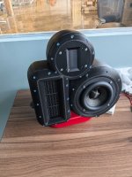
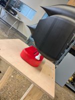
ENCLOSURE:
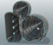
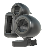
This is a 3d printed enclosure. The filament used here is carbon fiber infused PETG. It is dense, heavy, and rings super low. I have so much bracing in this unit and the walls are so thick I'm pretty sure I could park my Acura RSX on it without it failing. I'll throw up some pictures for you to see. This part was printed on a very large 3d printer and it took 3 days to print. In total it is 6 pounds of filament. This isn't your friends 3d printing. This is industrial grade. I have a few of these at work and use them all the time. This required the largest one we have.
The Planar Mid is sandwiched inside the enclosure between the face and the body. Behind the mid planar is a diffusion array. I tested a bunch of these. This one works the best by a long shot. Not exactly sure why. The back cup is filled with polyfill. There is a sheet of microfiber cloth between the fill and the planar so the poly fill fibers do not end up inside of the driver.
The enclosure is exactly 0.38' cube. I forget how long the port is but it is exact to what I wanted. Do not underestimate the amount of time it took me to create this model to EXACTLY 0.38' cube volume AND have the port the exact length. The port is the stand. It still in prototype stage but with eventually be 3d printed in the same black filament as the body.
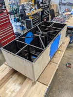
Coffee Table Subwoofer:
So this became of me just screwing around one night with WINISD. I needed a coffee table and didn't want a boring one. I run the fab shop of an engineering consulting company so I figured I might was well make the coffee table a sub and show off some fab skills. The volume is 13000" square. I forget the port length but there are two of them and they are 4" diameter. That is as wide of diameter as I could go without adding bends which I didn't want to do. They fire at the floor. The table will be 2" off of the floor. I won't get past the max port velocity until 200 watts so I think I am ok. I'll be powering it with a 200 watt RMS amplifier. I will run them in series for an 8 ohm impedence. This is an office so that should be sufficient. I'm not trying to shake the building down here.
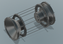
The woofers will be sandwiched between the middle bracing and the outer walls. They are more than snug. I already fitted that up. They will not be screwed to the sides. There will be 8 M5 threaded rods running through the entirety of the cabinet to link the two woofers. There are also some reinforcing rings midway so that the threaded rod doesn't try to bow as they run a decent distance.
I think the bracing is sufficient if not a little overboard. Again, I can probably park my Acura on this without it breaking.
The big party trick here is the top will be clear Acrylic. It will be screwed on with gasket on all the bracing to seal it. No way am I doing all this crazy engineering and then hiding it. Nope, I want everyone to see what is going on.
Measurements:
These will be coming soon. I just took them today. I will get them into VituixCAD and start messing with the crossover. I'll probably go with a 3 way series crossover. I like the flexibility of the series crossover. Less need for a bunch of components in the form of notch filters. The Mid planar and the Ribbon will both require some notches. I can already tell from the measurements. They do all measure very clean. These are much lower distortion drivers than anything I have used before. Anyways, coming soon, I am running out of time before I have to head out to dinner.
Thanks for reading. I should be done with the sub next week and the crossover within the next 2 weeks.
This build consists of 3 way nearfield monitors and a coffee table that is also a push-push bass reflex subwoofer.
This is in no way an "optimal" build. It was never supposed to be. It is meant to be an outlandish, exotic, fun build. I wanted to use different drivers, different configurations, different methods, different everything. I can build a two studio monitor and have it play back accurate. This is not that. That I could just buy. This is building something you cannot just buy. Something you'd have to make. Something you'd have to explain to even someone into audio.
OBJECTIVE:
Create an awesome 3 way setup with a sub that goes from 18 hz to 40K hz. Distorion under 2% for everything 200 hz and up. It needed it fit under my triple monitors and not take up too much office space. By making the coffee table for my office couch the sub I have succeeded for the sub. The 3 ways are pretty big but they tuck under the monitors which is dead space anyways. Budget was under $500. I think I might end up a little over with the crossover but we will see
Monitors:
Tweeter - GRS RT1.R - 5K hz and up $60 (on sale)
I hear good things about these ribbons. This is the first time I am using a ribbon tweeter. Hoping there isn't too steep of a learning curve. I took the measurements with a 45 uf cap. The sweep sounds insanely clean.
MID: - GRS 8" Mid Planar - 800-5k hz $55 (on sale)
This is another first, I have never used anything other than a cone driver for a mid so far. I did spent a ridiculous amount of time 3d printing horns. I learned a lot. I can get it go down to 500 hz cleanly but it requires a massive horn and that isn't the direction I wanted to go.
WOOFER: - Epique 5.5" MMAG Woofer $70 (on sale with coupon)
I was hesistant to go with this driver. It has measured out very well. With the port its hitting down into the 30s with ease. Impressive little thing. I got it on sale so not so bad. It has an incredible amount of XMAX. Interested to start working with this thing
Subwoofer: - GRS 12" High Excursion Paper Cone
Nothing special here. I have simulated these before and wondered how anyone could have a use for them since they require such a large box. Well, a coffee table is around 13000 inch square. So two of them work perfectly here.
ENCLOSURE:
This is a 3d printed enclosure. The filament used here is carbon fiber infused PETG. It is dense, heavy, and rings super low. I have so much bracing in this unit and the walls are so thick I'm pretty sure I could park my Acura RSX on it without it failing. I'll throw up some pictures for you to see. This part was printed on a very large 3d printer and it took 3 days to print. In total it is 6 pounds of filament. This isn't your friends 3d printing. This is industrial grade. I have a few of these at work and use them all the time. This required the largest one we have.
The Planar Mid is sandwiched inside the enclosure between the face and the body. Behind the mid planar is a diffusion array. I tested a bunch of these. This one works the best by a long shot. Not exactly sure why. The back cup is filled with polyfill. There is a sheet of microfiber cloth between the fill and the planar so the poly fill fibers do not end up inside of the driver.
The enclosure is exactly 0.38' cube. I forget how long the port is but it is exact to what I wanted. Do not underestimate the amount of time it took me to create this model to EXACTLY 0.38' cube volume AND have the port the exact length. The port is the stand. It still in prototype stage but with eventually be 3d printed in the same black filament as the body.
Coffee Table Subwoofer:
So this became of me just screwing around one night with WINISD. I needed a coffee table and didn't want a boring one. I run the fab shop of an engineering consulting company so I figured I might was well make the coffee table a sub and show off some fab skills. The volume is 13000" square. I forget the port length but there are two of them and they are 4" diameter. That is as wide of diameter as I could go without adding bends which I didn't want to do. They fire at the floor. The table will be 2" off of the floor. I won't get past the max port velocity until 200 watts so I think I am ok. I'll be powering it with a 200 watt RMS amplifier. I will run them in series for an 8 ohm impedence. This is an office so that should be sufficient. I'm not trying to shake the building down here.
The woofers will be sandwiched between the middle bracing and the outer walls. They are more than snug. I already fitted that up. They will not be screwed to the sides. There will be 8 M5 threaded rods running through the entirety of the cabinet to link the two woofers. There are also some reinforcing rings midway so that the threaded rod doesn't try to bow as they run a decent distance.
I think the bracing is sufficient if not a little overboard. Again, I can probably park my Acura on this without it breaking.
The big party trick here is the top will be clear Acrylic. It will be screwed on with gasket on all the bracing to seal it. No way am I doing all this crazy engineering and then hiding it. Nope, I want everyone to see what is going on.
Measurements:
These will be coming soon. I just took them today. I will get them into VituixCAD and start messing with the crossover. I'll probably go with a 3 way series crossover. I like the flexibility of the series crossover. Less need for a bunch of components in the form of notch filters. The Mid planar and the Ribbon will both require some notches. I can already tell from the measurements. They do all measure very clean. These are much lower distortion drivers than anything I have used before. Anyways, coming soon, I am running out of time before I have to head out to dinner.
Thanks for reading. I should be done with the sub next week and the crossover within the next 2 weeks.
Attachments
-
 PXL_20241228_205117938.jpg452.1 KB · Views: 368
 -
 PXL_20241228_205126020.jpg400 KB · Views: 328
 -
 1000006017.jpg437.9 KB · Views: 290
 -
 PXL_20241228_154029416.jpg524.8 KB · Views: 291
 -
 PXL_20241228_143957886.jpg674.3 KB · Views: 299
 -
 PXL_20241228_143959632.jpg686.1 KB · Views: 307
 -
 PXL_20241228_205119786.jpg406.7 KB · Views: 322
 -
 PXL_20241228_163426459.jpg555.6 KB · Views: 346
 -
 Screenshot 2024-12-28 162120.png1,009.1 KB · Views: 327
 -
 Screenshot 2024-12-28 162141.png547.6 KB · Views: 330
 -
 Screenshot 2024-12-28 165647.png850.6 KB · Views: 329
 -
 Screenshot 2024-12-28 165624.png1.2 MB · Views: 364

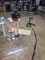
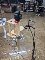
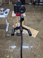
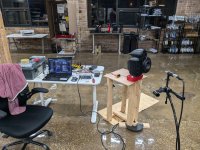
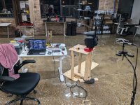
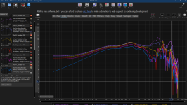
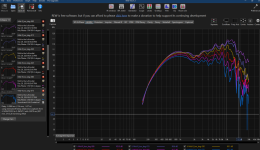
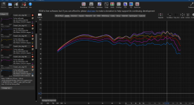
Got the measurements. I had to design this little jig to take the measurements. I didn't know how else to get the mic into three VERY different positions without throwing off the z offset. Was a bit difficult to position but I figured it out.
The tweeter looks very clean. I was right in thinking it was only to be used above 5k. Right where I planned the crossover. Distortion is very low.
The mid is going to take some beating into shape. This is where I think the series XO is going to shine. Also, very low distortion.
The Epique 5.5 is super surprising. This thing is the deal of the decade. Look at this distortion. It plays incredibly low.
All in I'm looking at under 1% for the whole range outside of very low bass.
Speaking of bass, WOWZA, does this thing hit low. F3 of 32 hz is pretty nuts for something that sits on my desktop
However...... I seem to have a big problem here. I am crossing this Epique around 800-1000hz. There is a nasty port resonance at 800 hz. It is really bad. I don't think I can filter this out. I may have to design a new port. Right now it is side firing. I think I can minimize its effects if I rear fire the port. It might need one of those stubs too. Not sure yet. I may have to make it larger in area and longer. That will require two bends.
Back to the 3d modeling I guess......
Attachments
-
 PXL_20241230_022635417.jpg821.9 KB · Views: 156
 -
 PXL_20241230_030437031.jpg831.1 KB · Views: 158
 -
 PXL_20241230_022640279.jpg486.4 KB · Views: 153
 -
 PXL_20241230_030441064.jpg712.9 KB · Views: 149
 -
 PXL_20241230_030443129.jpg689.5 KB · Views: 163
 -
 Screenshot 2024-12-30 220356.png978.6 KB · Views: 161
 -
 Screenshot 2024-12-30 220405.png652.4 KB · Views: 154
 -
 Screenshot 2024-12-30 220328.png662.7 KB · Views: 149
 -
 Screenshot 2024-12-30 220319.png933.7 KB · Views: 143
 -
 Screenshot 2024-12-30 220250.png582.5 KB · Views: 150
 -
 Screenshot 2024-12-30 220229.png767.4 KB · Views: 150
 -
 Screenshot 2024-12-30 220158.png835.6 KB · Views: 177
Very cool! I think you’ll, like that tweetI think I'm about 3 months into this project so far but I'm now going to start the build thread.
This build consists of 3 way nearfield monitors and a coffee table that is also a push-push bass reflex subwoofer.
This is in no way an "optimal" build. It was never supposed to be. It is meant to be an outlandish, exotic, fun build. I wanted to use different drivers, different configurations, different methods, different everything. I can build a two studio monitor and have it play back accurate. This is not that. That I could just buy. This is building something you cannot just buy. Something you'd have to make. Something you'd have to explain to even someone into audio.
OBJECTIVE:
Create an awesome 3 way setup with a sub that goes from 18 hz to 40K hz. Distorion under 2% for everything 200 hz and up. It needed it fit under my triple monitors and not take up too much office space. By making the coffee table for my office couch the sub I have succeeded for the sub. The 3 ways are pretty big but they tuck under the monitors which is dead space anyways. Budget was under $500. I think I might end up a little over with the crossover but we will see
Monitors:
Tweeter - GRS RT1.R - 5K hz and up $60 (on sale)
I hear good things about these ribbons. This is the first time I am using a ribbon tweeter. Hoping there isn't too steep of a learning curve. I took the measurements with a 45 uf cap. The sweep sounds insanely clean.
MID: - GRS 8" Mid Planar - 800-5k hz $55 (on sale)
This is another first, I have never used anything other than a cone driver for a mid so far. I did spent a ridiculous amount of time 3d printing horns. I learned a lot. I can get it go down to 500 hz cleanly but it requires a massive horn and that isn't the direction I wanted to go.
WOOFER: - Epique 5.5" MMAG Woofer $70 (on sale with coupon)
I was hesistant to go with this driver. It has measured out very well. With the port its hitting down into the 30s with ease. Impressive little thing. I got it on sale so not so bad. It has an incredible amount of XMAX. Interested to start working with this thing
Subwoofer: - GRS 12" High Excursion Paper Cone
Nothing special here. I have simulated these before and wondered how anyone could have a use for them since they require such a large box. Well, a coffee table is around 13000 inch square. So two of them work perfectly here.
ENCLOSURE:
This is a 3d printed enclosure. The filament used here is carbon fiber infused PETG. It is dense, heavy, and rings super low. I have so much bracing in this unit and the walls are so thick I'm pretty sure I could park my Acura RSX on it without it failing. I'll throw up some pictures for you to see. This part was printed on a very large 3d printer and it took 3 days to print. In total it is 6 pounds of filament. This isn't your friends 3d printing. This is industrial grade. I have a few of these at work and use them all the time. This required the largest one we have.
The Planar Mid is sandwiched inside the enclosure between the face and the body. Behind the mid planar is a diffusion array. I tested a bunch of these. This one works the best by a long shot. Not exactly sure why. The back cup is filled with polyfill. There is a sheet of microfiber cloth between the fill and the planar so the poly fill fibers do not end up inside of the driver.
The enclosure is exactly 0.38' cube. I forget how long the port is but it is exact to what I wanted. Do not underestimate the amount of time it took me to create this model to EXACTLY 0.38' cube volume AND have the port the exact length. The port is the stand. It still in prototype stage but with eventually be 3d printed in the same black filament as the body.
Coffee Table Subwoofer:
So this became of me just screwing around one night with WINISD. I needed a coffee table and didn't want a boring one. I run the fab shop of an engineering consulting company so I figured I might was well make the coffee table a sub and show off some fab skills. The volume is 13000" square. I forget the port length but there are two of them and they are 4" diameter. That is as wide of diameter as I could go without adding bends which I didn't want to do. They fire at the floor. The table will be 2" off of the floor. I won't get past the max port velocity until 200 watts so I think I am ok. I'll be powering it with a 200 watt RMS amplifier. I will run them in series for an 8 ohm impedence. This is an office so that should be sufficient. I'm not trying to shake the building down here.
The woofers will be sandwiched between the middle bracing and the outer walls. They are more than snug. I already fitted that up. They will not be screwed to the sides. There will be 8 M5 threaded rods running through the entirety of the cabinet to link the two woofers. There are also some reinforcing rings midway so that the threaded rod doesn't try to bow as they run a decent distance.
I think the bracing is sufficient if not a little overboard. Again, I can probably park my Acura on this without it breaking.
The big party trick here is the top will be clear Acrylic. It will be screwed on with gasket on all the bracing to seal it. No way am I doing all this crazy engineering and then hiding it. Nope, I want everyone to see what is going on.
Measurements:
These will be coming soon. I just took them today. I will get them into VituixCAD and start messing with the crossover. I'll probably go with a 3 way series crossover. I like the flexibility of the series crossover. Less need for a bunch of components in the form of notch filters. The Mid planar and the Ribbon will both require some notches. I can already tell from the measurements. They do all measure very clean. These are much lower distortion drivers than anything I have used before. Anyways, coming soon, I am running out of time before I have to head out to dinner.
Thanks for reading. I should be done with the sub next week and the crossover within the next 2 weeks.
Did a little bit more work today.
I swapped out the stuffing behind the mid planar. I went from poly fill to R14 rockwool. I see significant benefits in the high end. If I ran running it full range this would be crucial. Since I am not it just helps me with the crossover point of 5k hz.
I stuffed a lot of rockwool behind the woofers and tested out the port resonance. It did lower the port resonance issue. What I believe to be 2nd order resonance was decreased greatly.
A while back I was screwing around with horns. I learned about back loaded horn offsetting. Since my port is external and has a 90 degree in it I am going to try to "offset" it. I will add a chamber at the end. I will take the measurement, then I will stuff that end with rockwool, and test it again.
This should, in theory, help with the peaks. If it does, I will probably need to do more work. I can round off the 180 bend. I think that would be the next thing to try. I can make it more of a long, smooth arc, instead of two 90 degree elbows. My guess is this is a big part of my problem.
If none of that works I will either back fire the port or just give up and seal her up.
Attachments

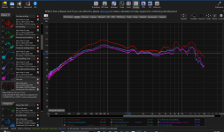
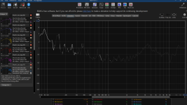
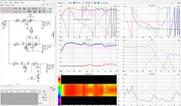
I modified the port and smoothed out the resonances a bit. I do have this horrendous peak.
I think it is going to have to be a heimholtz resonantor coming off of the port to fix it.
Anyways...here is the current XO. It contains only the off axis to the right of the enclosure. As it is meant to be listened to between them nearfield there is no reason to add in the the other off axis. It would literally be impossible to go off axis to the left. The other one will be mirrored.
You can see the port resonance peak in the simulated response.
Attachments
If you are crossing to a sub-woofer make it sealed to get rid of the port resonance? Dayton lists the F3 of a .15 ft3 enclosure as 82.2 hz.
Fair enough. Dunno where the speaker is pointed at. I suppose it is designed for a mm-specific fixed listening position.
That is definitely an option.If you are crossing to a sub-woofer make it sealed to get rid of the port resonance? Dayton lists the F3 of a .15 ft3 enclosure as 82.2 hz.
I do want them to be a standalone design that doesn't rely on a giant coffee table Subwoofer for the full frequency of sound.
I plan to look into seeing if I can utilize a couple of resistors so I can switch from full range to sealed with the XO. I am a ways away from that yet.
I hadn't added them yet. I am a ways away from the polished design. Right now I am working on fixing the port resonance.Um, how come all of your drivers have a non-zero X and Y offset in vituixcad? The tweeter is the reference.
They are included in the newer crossover work
It meant to be listened to very closely so it does matter here. If it were designed for a large room then yes, I could probably get away with that.It's possible if you measure all the drivers without moving the mic, given that the speaker is not so big.
I could not find the actual specs for the passive radiators. They do not give me enough data to simulate them so I decided not to try to use them.What about passive radiator? (But I think the Epique 5" requires TWO of the PRs, not sure if you have a place to put them.)
A passive would entirely change the shape. I think it would have to be a cylinder then. I modeled this and did not like the shape cosmetically.
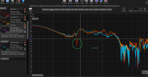
Well, then heimholtz resonators do work.
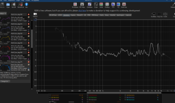
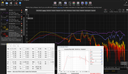
I designed it for 350 hz. Why then is it as around 315 hz you ask?
Let me explain. 3D printers have a tendency to print circles slightly smaller than you model them. You actually have to design with this in mind. I did not. I screwed up. So the neck ended up 0.45mm smaller in radius. Which actually puts me exactly at a calculated 315 hz, exactly as the data shows.
As you can see, the frequency band in which the resonator works is relatively narrow. I need to knock down a bandwidth around 60-80 hz. This means it may require 2-3 resonators to knock down the resonance.
And here lies the joy of 3d modeling and 3d printing. I can just print a bunch of resonators and try them out. This set should cover the full bandwidth from 310 hz to 410 hz. I will try them out tomorrow and see what combo works. I will then incorporate them into the design so they are more ascetically pleasing.
Attachments

Volume is cubed, not squared. 13,000in^3 or cubic inches, or roughly 7.5 cubic feet. I hope you wanted it that large.
PRs, yes, 2x 5.5" or a single 7" PR for the single 5.5" woofer.
I don't understand what you mean by printing resonators, nor that the Fb of box is in the 300Hz+ range. What would resonate that high?
Q: Do you have the midrange chamber volume isolated from the woofer chamber? It looks as though there is an open channel between them. This is not a good idea, and since the 8" is an open back planar design, the woofer will make the midrange oscillate in response to whatever it moves.
Typo, this group absolutely loves to point out semanticsVolume is cubed, not squared. 13,000in^3 or cubic inches, or roughly 7.5 cubic feet. I hope you wanted it that large.
The resonators go in the port. They are heimholtz resonators for the port resonance. As I stated above. The stated "port resonance peak" refers to a port resonance, pretty clear. The woofer plays up to 800 hz as stated previously in the build thread. Please read the build thread. I will not be repeating things for you past this point.
The midrange does have its own chamber. I suppose I didn't add what the inside of this thing looks like. It has its own stuffing and its own diffuser. Out of 6 diffuser desings, this is the one that worked the best. Also stated previously in this build thread. It is totally isolated from the woofer. As this is a dipole planar, I think if it weren't isolated this entire thing wouldn't work at all.I don't understand what you mean by printing resonators, nor that the Fb of box is in the 300Hz+ range. What would resonate that high?
Q: Do you have the midrange chamber volume isolated from the woofer chamber? It looks as though there is an open channel between them. This is not a good idea, and since the 8" is an open back planar design, the woofer will make the midrange oscillate in response to whatever it moves.
It is a coffee table. It is pretty big. My office is quite large. It has a couch and a work bench in it.Volume is cubed, not squared. 13,000in^3 or cubic inches, or roughly 7.5 cubic feet. I hope you wanted it that large.
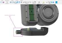
Is that supposed to be a closed-ended-stub to stifle the upper band resonance of the port? If that is the case, you need the same entry area as the port cross sectional area to allow it to work optimally. Just having a hole in it won't suffice.
Is that stub filled with felt or any other kind of damping? If no absorptive material or structure is present, it won't do its job.
Is that stub filled with felt or any other kind of damping? If no absorptive material or structure is present, it won't do its job.
I am not sure what a "closed-ended-stub" is. This is a Heimholtz resonator. You can fill it with wadding but it is unnecessary and I've not seen a report of that helping. It acts as a spring that works in a specific frequency band by absorbing said frequency.Is that supposed to be a closed-ended-stub
You can see in the graph above how it absorbed 35 decibel of sound out the port's frequency response at around 315 hz. They are quite effective.
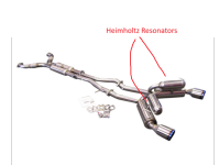
We use these a lot in our track cars. A lot of tracks have a decibel limit. Most exhausts have a resonance peak. Mine, for example, has a nasty resonance peak at 100 hz. So we add heimholtz resonators to the exhaust just before the muffler. Calculated properly they kill that resonance and lower you max decibel level so you can run at the track without a restrictive exhaust system. I will throw up a picture of such a system. This exhaust is very similar to the one on my own car.
The port of a speaker has similar characteristics. Apparently, these work just as well on ports as they do on exhaust systems.
Attachments
- Home
- Loudspeakers
- Multi-Way
- 3 Way Bullet Build - Official epic awesome office build thread