Sorry, used the wrong words; closed ended quarter wave stub. Could not recall it last night. There have been several builds using such a device to eliminate the upper harmonic resonance of a Helmholtz tuned port or traditional venting cylindrical ports to clean up their performance. Helmholtz refers to the port or exhaust itself, and not the tuned stub. The correct length of the stub, and added damping improved their effectiveness. I had no idea this kind of thing was used in exhaust systems, but I can understand why and that it would work to a varying degree. However, damping in a hot exhaust might be difficult to implement.
Over on PETT or MAC forums, there is a build by 4thtry called the Plumber's Delights that uses this kind of port augmentation.
How are you varying the tuning of the devices? Internal length?
Over on PETT or MAC forums, there is a build by 4thtry called the Plumber's Delights that uses this kind of port augmentation.
How are you varying the tuning of the devices? Internal length?
Wolf,
There are really a few ways to tune the resonator.
The parameters are as follows:
1. Internal Volume
2. Neck Volume
I am using cylinders to keep it at four parameters which are as follows:
1. Internal radius - set to 20mm for now
2. Internal length - set to 60mm for now
3. Neck Radius - set to 5mm for now (this is by far the most crucial length as fractions of a mm matter here)
4. Neck Length - set to 25mm for now
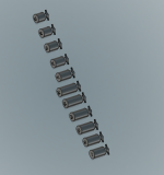
Today I decided to play with the neck radius as this would also allow me to fine tune the filament profile so I get exact diameters when I 3d print it again. Two birds, one stone.
The resonantor's neck length varied between 10mm and 11.4. The actual measurements taken varied from 9.6mm to 11.15mm. As you can see, it is not a 1:1 ratio being off with circles when 3d printing.
I will show the results. As the neck gets wider, the frequency the resonator kills goes up.
This is not a wide enough spread but the large neck opening puts me pretty close to dead in the middle.
It is pretty apparent that I will need three resonators. I will make 10 more resonators that vary in internal volume. These I will vary 5mm either way. The shorter ones will kill a higher frequency. The longer ones will kill a lower frequency.
I will print these overnight and test them tomorrow. If I am lucky, I will find two perfectly at the other two peaks. I will then run three resonators along the port. The main one should be at the main peak. I forget if the higher or lower frequency resonator needs to be closer to the exit or further away. Easily testable by switching them around.
Anyways, I will post more results tomorrow.
What is PETT or MAC? I am not on those forums. It would be interesting to see how someone else has tackled this same issue. I am far from pioneering but I am stumbling my way through. So far, with quite a degree of success.
There are really a few ways to tune the resonator.
The parameters are as follows:
1. Internal Volume
2. Neck Volume
I am using cylinders to keep it at four parameters which are as follows:
1. Internal radius - set to 20mm for now
2. Internal length - set to 60mm for now
3. Neck Radius - set to 5mm for now (this is by far the most crucial length as fractions of a mm matter here)
4. Neck Length - set to 25mm for now
Today I decided to play with the neck radius as this would also allow me to fine tune the filament profile so I get exact diameters when I 3d print it again. Two birds, one stone.
The resonantor's neck length varied between 10mm and 11.4. The actual measurements taken varied from 9.6mm to 11.15mm. As you can see, it is not a 1:1 ratio being off with circles when 3d printing.
I will show the results. As the neck gets wider, the frequency the resonator kills goes up.
This is not a wide enough spread but the large neck opening puts me pretty close to dead in the middle.
It is pretty apparent that I will need three resonators. I will make 10 more resonators that vary in internal volume. These I will vary 5mm either way. The shorter ones will kill a higher frequency. The longer ones will kill a lower frequency.
I will print these overnight and test them tomorrow. If I am lucky, I will find two perfectly at the other two peaks. I will then run three resonators along the port. The main one should be at the main peak. I forget if the higher or lower frequency resonator needs to be closer to the exit or further away. Easily testable by switching them around.
Anyways, I will post more results tomorrow.
What is PETT or MAC? I am not on those forums. It would be interesting to see how someone else has tackled this same issue. I am far from pioneering but I am stumbling my way through. So far, with quite a degree of success.
Attachments


Alright, so here is what I am finding.
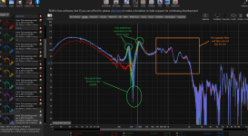
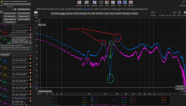
Yes, you can kill a specific resonant frequency in a port. However, you will gain two new peaks right next to it.
You can try to put more of them in there but you'd need a lot to kill all the peaks. Possibly 5. With three I am just making the response more jagged.
I can either have one big peak or three little peaks. I can try a test with 5 but I think this is a losing a battle.
I can run the port when I want the bass and then seal it when I don't. When I seal it I can run it through two slightly higher resistors for the Ribbon and the planar. This should level everything out. Then I can choose what I want to play
Attachments
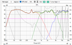
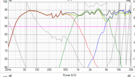
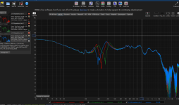
It looks like the bass rolls off more in the first graph, which I assume is with the resonator, than in the second graph. The F3 looks to change from 38 hz to about 30 hz. Or it could just be a measurement problem.
Yes, it does take some energy away from the bass which I why I think its better to just deal with the one peak.It looks like the bass rolls off more in the first graph, which I assume is with the resonator, than in the second graph. The F3 looks to change from 38 hz to about 30 hz. Or it could just be a measurement problem.
I will see if I can notch filter it out. I have tried that before but without success. I will try again
I am not having any success creating a notch filter. Does anyone want to take a crack at it? I can post up all the files
Re: port pipe resonances, don't know if this is relevant here, but I wrap my PVC pipe ports with a layer of felt, to dampen them, and ensure the wall opposite the internal end of the pipe is covered in felt, to minimise internal reflections down the pipe
You are talking about lining the inside of the port? I am up for trying this. Makes perfect sense to me.Re: port pipe resonances, don't know if this is relevant here, but I wrap my PVC pipe ports with a layer of felt, to dampen them, and ensure the wall opposite the internal end of the pipe is covered in felt, to minimise internal reflections down the pipe
What felt do you use? I've noticed, when looking for felt in the past, that there are 1000 different kinds.
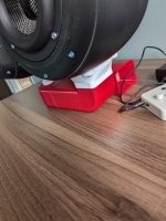
The port is external to the enclosure. I generally wrap the outside of the port when I port a regular cabinet with the port inside. I'm not sure wrapping this would have any effect.re: lining the inside of the port?' = no, the outside
the felt is from an old removalist's blanket I scavenged
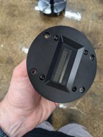
The red/white stand is the port.
Attachments
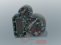
I don't know whether this has been mentioned, but the shape of the mid-woof enclosure is close to a sphere, so consider the possibility that the resonance is internal standing waves, which are known to plague this shape of enclosure
I am thinking this is part of the problem. I can move the port entrance to the other side of the enclosure. By then the standing waves should be broken up.I don't know whether this has been mentioned, but the shape of the mid-woof enclosure is close to a sphere, so consider the possibility that the resonance is internal standing waves, which are known to plague this shape of enclosure
What do you think?
I have to reprint the whole enclosure anyways.....details in next post
Attachments
I was testing the woofer today and I have a big problem.
I didn't make a cup for the ribbon tweeter because I thought, mistakingly, that it was sealed off. It is definitely NOT sealed.
When the woofer hits you can hear the ribbon vibrating horribly. I thought it was the motor of the woofer at first but it is, in fact, the ribbon moving.
I could try dipping the back of the tweeters in epoxy but I think the best thing to do is to print a new back shell that has a cup behind the ribbon to protect it from internal waves. Thoughts from anyone?
Attachments

Are you certain it's not that the ribbon is not rolled off enough, or protected from the bass range enough? I've never heard of anybody having to seal Fountek ribbons off in the past.
The ribbon wasn't hooked up to the amplifier. The only thing playing was the woofer. We were playing it full range.Are you certain it's not that the ribbon is not rolled off enough, or protected from the bass range enough? I've never heard of anybody having to seal Fountek ribbons off in the past.
Took us about 5 minutes to figure it out but it is definitely the ribbon moving from the air of the woofer.
We have Bass Makanic playing and that woofer has 12mm of xmax. There was A LOT of air moving around
It's not a fountek. It's a GRS ribbonFountek ribbons off in the past.
Then it was electrically undamped, it's membrane would flop around sympathetically.The ribbon wasn't hooked up to the amplifier.
Short it out, or connect it to the amp (generally they are very low impedance when powered up, but many disconnect the speaker when off) and test again.
"Bass I Love You", down to ~8Hz, Noise I Hate You!We have Bass Makanic playing and that woofer has 12mm of xmax. There was A LOT of air moving around
Yes, if you fly a ribbon or a piece of paper near the speaker you will hear it flap in the breeze.
As to the bass reflex port resonance issue, trying to correct a port resonance with an electrical filter would reduce the excitation of the peak, but then you may hear that range (delayed by the length of the port..) more from the port than the driver, not good, hifi fans..
Have you tried firing the port into some fiberglass or rock wool, or a printed metamaterial sound absorber?
https://pubs.aip.org/aip/apl/articl...7/Acoustic-metamaterial-absorbers-The-path-to
That should knock out the upper crap above 200Hz by a good margin without reducing the LF output.
Art
- Home
- Loudspeakers
- Multi-Way
- 3 Way Bullet Build - Official epic awesome office build thread