I have considered this. I am going to see if I can fix it mechanically before taking such a measure.Have you tried firing the port into some fiberglass or rock wool, or a printed metamaterial sound absorber?
I have tried adding stuffing to the port but that attacks the whole thing.
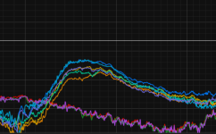
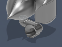
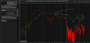
Today I tried an "offset port". Took a lesson out of the offset horn book so to speak. I fill the offset with damping and see what it does. It does help. It reduces the bass output but it reduces the resonance more. Its not much, but it progress. See the pictures. Check out the orange line. That is melamine inside the offset port
Attachments
The model now has a back cup. No more ribbon flappin in the breeze as welter said
I will have to reprint this entire back half of the enclosure. However, I had the cooling set way too high for the last print which caused some unsightly lines. So yes, it will cost about $65 to reprint it but, it should have significantly better quality than the current one. In my experience, 3d printing gets weird when the models get very large. What works on a 100mm model doesn't really translate to a 350mm model
I will have to reprint this entire back half of the enclosure. However, I had the cooling set way too high for the last print which caused some unsightly lines. So yes, it will cost about $65 to reprint it but, it should have significantly better quality than the current one. In my experience, 3d printing gets weird when the models get very large. What works on a 100mm model doesn't really translate to a 350mm model
Attachments

You said "The ribbon wasn't hooked up to the amplifier." when you heard it flap.The model now has a back cup. No more ribbon flappin in the breeze as welter said
The back cup won't keep the "remarkably thin" ribbon from flapping if it's not hooked up to the amplifier (or the voice coil shorted out), and will reduce power handling and increase thermal compression if the heat sink is enclosed.
I don't know that you understand the situation. The air from the back of the woofer was pushing through the back cup of the ribbon which caused the ribbon to move, which made noise.You said "The ribbon wasn't hooked up to the amplifier." when you heard it flap.
The back cup won't keep the "remarkably thin" ribbon from flapping if it's not hooked up to the amplifier (or the voice coil shorted out), and will reduce power handling and increase thermal compression if the heat sink is enclosed.
An un-terminated diaphragm sealed from a woofer back chamber can move wildly in the presence of high SPL low frequency sound.I don't know that you understand the situation. The air from the back of the woofer was pushing through the back cup of the ribbon which caused the ribbon to move, which made noise.
How did you determine or verify the back cup of the tweeter was not air tight?
Last edited:
As another example, this is the main reason ribbon drivers are not used in automotive situations. Shutting a car door can blow out the membrane without being a sandwich or reinforced style. Many ribbon drivers have slip covers for protection when not in use. Output or air pressure changes can make sympathetic diaphragms oscillate regardless of internal cabinet volume pressures.

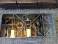
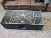
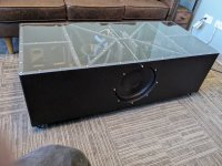
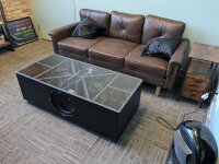
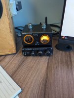
As the nearfield 3 ways are getting a port redesign I was able to finish the subwoofer coffee table.
This thing came out WAY better than I expected. It hits so hard. It doesn't need hardly any wattage to slam.
I currently have it wired up 8 ohm in series out of a fosi audio M01-BT sub amp. Seems like its doing just fine.
It is wrapped in leather. Staining the inside really sucked. I poly coated the inside as well just for protection. I did most of this work christmas even and christmas day inbetween holiday parties.
Wrapping the wood in leather was definitely a learning curve.
I really have no idea how to measure this with all the room reflections and what not. With the ports coming out below, 2" from the ground, measuring the port on its side wouldn't likely be too accurate. Anyone know how to measure something like this?
Attachments

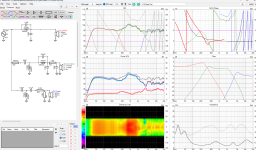
Hornresp is awesome.
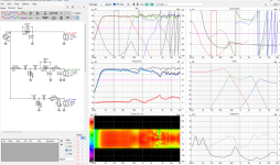
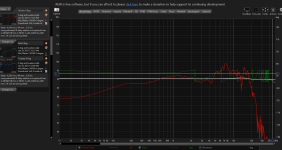
I have learned that anytime I design a port I should run a sim in Hornresp to check out the resonances.
I shortened the port and make the square area smaller. Modelling this in hornresp pushed out the resonance past 500. The sim was within 30 hz. Pretty cool. Definitely made by people much smarter than I. This port looks a lot cooler as well.
All I need to do now is tame this frustrating planar mid then polish up this XO and I'm good to go. On to the next couple of week of fiddling around.
As an aside and so this all gets into one place. I sought some help trying to notch filter out that old 340 hz resonance. It was failure city. Changing the port was the only real solution. Link:
I am building this 3 way for my desktop. I am sure some of you have seen my previous posts.
The main build thread is here: https://www.diyaudio.com/community/...ffice-build-thread.421776/page-2#post-7890664
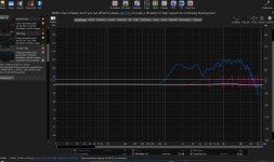
Can someone take a whack at notching out this 340 hz peak for me? I will attach the full data packet
I am having zero success notching out this 340 hz peak in the woofer response. This is a cause of the port resonance which is, itself, the cause of me crossing the woofer at 800 hz.
I have tried 4 different port designs and...
The main build thread is here: https://www.diyaudio.com/community/...ffice-build-thread.421776/page-2#post-7890664
Can someone take a whack at notching out this 340 hz peak for me? I will attach the full data packet
I am having zero success notching out this 340 hz peak in the woofer response. This is a cause of the port resonance which is, itself, the cause of me crossing the woofer at 800 hz.
I have tried 4 different port designs and...
Attachments
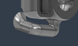
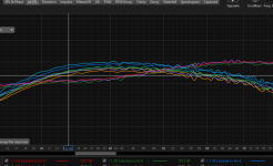
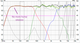
I finished off the 1st iteration of XO last night. That bump in low end was bothering me. I fixed it by constricting the port a further 2mm. I flared the ends a bit more as well. Its getting to be quite a complex design. Its basically a folded flared horn.
I see the constriction has taken a tiny bit more out the lowest end than I'd like so I'll be printing one more port that is 1.8mm constricted. This should land about perfect so I will print this nice and slow out of the very good, low resonance, PETG-CF filament
I am also going to try out this full length flare port just for fun. I just want to see what it does to the resonance to flare the whole length. Might as well gain some data and experience while I am here.
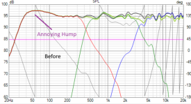
Here is the finished XO as well as the before and after the 2mm constriction of the port
I see the constriction has taken a tiny bit more out the lowest end than I'd like so I'll be printing one more port that is 1.8mm constricted. This should land about perfect so I will print this nice and slow out of the very good, low resonance, PETG-CF filament
I am also going to try out this full length flare port just for fun. I just want to see what it does to the resonance to flare the whole length. Might as well gain some data and experience while I am here.
Here is the finished XO as well as the before and after the 2mm constriction of the port
Attachments

You can filter the bass with some large x-over values in an LCR notch. Toss this in your sim, and then alter the values to move the effect around. I'm going from memory. 10mH, 600uf, and about 6 ohms, all in series with each other, and placed across the driver leads.
That impedance sure looks low. I can help you with that if you want. But if you are like me, you may want to figure it out without help. Maybe your amp can handle it just fine anyway.
That impedance sure looks low. I can help you with that if you want. But if you are like me, you may want to figure it out without help. Maybe your amp can handle it just fine anyway.
Last edited:
I'm back!
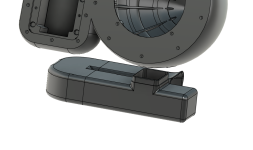
I had to reprint the entire back enclosure. The design required a back cup for the tweeter so that the back waves off of the woofer would not affect the tweeter. The GRS Rt1R back cup is NOT sealed.
So the original back side was trash. $80 of filament down the drain. I had two more prints fail printing the new one. Another $70 down. The third attempt succeeded and the print is suberb. 3D printing something of this size requires very different settings from printing something of small or moderate size. Definitely a learning curve there.
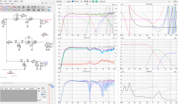
I retook all of the measurements. I used a class AB amp for this instead of the D. I took the measurements back to back with the D and they are incredibly similar but something in me trusts the AB more. Less peaky.
I did not use a cap when I tested the ribbon. It did not kill the amplifier. Now I know for a fact that the tweeter is in the proper phase which is good. Entering this new data into my old XO showed that the old measurements phase was not quite right. And phase here, is incredidly important as these drivers do not want to play nice with eachother.
Actually, these drivers are a pain in the butt. I'll show in the thumbnails what I'm dealing with. I am taking these 3 crazy responses and beating them into submission to make an accurate, flat response. This is hard.
I am struggling with phase issues at my XO points. I think the best thing to do is keep the XO points outside of the vocal range. The current one has the woofer to mid XO a little too high at 800 hz. I can get this down to 400-500. It will just take me a while. I have some work ahead of me.
I had to reprint the entire back enclosure. The design required a back cup for the tweeter so that the back waves off of the woofer would not affect the tweeter. The GRS Rt1R back cup is NOT sealed.
So the original back side was trash. $80 of filament down the drain. I had two more prints fail printing the new one. Another $70 down. The third attempt succeeded and the print is suberb. 3D printing something of this size requires very different settings from printing something of small or moderate size. Definitely a learning curve there.
I retook all of the measurements. I used a class AB amp for this instead of the D. I took the measurements back to back with the D and they are incredibly similar but something in me trusts the AB more. Less peaky.
I did not use a cap when I tested the ribbon. It did not kill the amplifier. Now I know for a fact that the tweeter is in the proper phase which is good. Entering this new data into my old XO showed that the old measurements phase was not quite right. And phase here, is incredidly important as these drivers do not want to play nice with eachother.
Actually, these drivers are a pain in the butt. I'll show in the thumbnails what I'm dealing with. I am taking these 3 crazy responses and beating them into submission to make an accurate, flat response. This is hard.
I am struggling with phase issues at my XO points. I think the best thing to do is keep the XO points outside of the vocal range. The current one has the woofer to mid XO a little too high at 800 hz. I can get this down to 400-500. It will just take me a while. I have some work ahead of me.
Attachments

I'll ask again, how did you determine or verify the back cup of the tweeter was not air tight?The GRS Rt1R back cup is NOT sealed.
Do you mean correct polarity?Now I know for a fact that the tweeter is in the proper phase which is good.
Do you mean your measurement wasn't properly executed, resulting in far more degrees of phase rotation than would be expected given the frequency response?Entering this new data into my old XO showed that the old measurements phase was not quite right.
Cheers,
Art
You can literally blow into one of the holes on the back and the ribbon will make noiseI'll ask again, how did you determine or verify the back cup of the tweeter was not air tight?
No, phase. Putting a cap in series in front of a driver throws its phase off. Even a 45uf cap would have it slightly off phase at the deemed XO point.Do you mean correct polarity?
Yes, this new setup with it much higher up gave me much better results. I didn't have to gate the mid so high which means it is more accurate and the tweeter I didn't have to gate at all. The tweeter was taken with no cap inline so I know the phase is correct.Do you mean your measurement wasn't properly executed, resulting in far more degrees of phase rotation than would be expected given the frequency response?
That's definitely a manufacturing defect. The manufacturer should replace the defective driver (s).You can literally blow into one of the holes on the back and the ribbon will make noise
Are you positive the "remarkably thin ribbon diaphragm" wasn't also damaged by that leakage?
Yes, 90 degree phase rotation per crossover "pole".Putting a cap in series in front of a driver throws its phase off. Even a 45uf cap would have it slightly off phase at the deemed XO point.
You will know the phase is "correct" when you measure ~90 degree phase change for a 6dB per octave frequency response change.The tweeter was taken with no cap inline so I know the phase is correct.
If you measure much more phase change than that, something (like delay/timing offset) is incorrect.
Well they both do it so I think that's just the design. I don't think the ribbon is damaged as it measures exactly the same as it did before. I used a hivi planar tweeter in another build. That one looks like it is sealed but someone else told me that it most definitely is not. Lesson here is, unless you can SEE for sure that is sealed up, assume it is not sealed.That's definitely a manufacturing defect. The manufacturer should replace the defective driver (s).
Are you positive the "remarkably thin ribbon diaphragm" wasn't also damaged by that leakage?
According to my measurements this delay should be nearly perfect. I baked into the 3d model my theorized z offsets for the drivers so they would be as close to time aligned as I could get them. I got pretty close with the woofer at -84mm delay, the mid at -82mm delay, and the tweeter at -86 delay. In terms of guesstimations.... thats pretty close to dead on.You will know the phase is "correct" when you measure ~90 degree phase change for a 6dB per octave frequency response change.
If you measure much more phase change than that, something (like delay/timing offset) is incorrect.
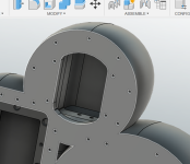
I must've printed 30 different ports before landing on this one. Gets low, doesn't have a resonance within the frequency band, and it is printable. This angle points it directly at my head


Just a thought. Someone mentioned that an amplifier doesn't like the ribbon impedance. This could work without a cap.
What if you pad the driver with 2 resistors in the typical fashion by say 2dB, and increase the amp gain by that same 2dB.
Or adjust the whole frd in Excel after the measurement. Sweep at a safe dB, and increase values by 8dB, or whatever to bring it up to the real SPL..
What if you pad the driver with 2 resistors in the typical fashion by say 2dB, and increase the amp gain by that same 2dB.
Or adjust the whole frd in Excel after the measurement. Sweep at a safe dB, and increase values by 8dB, or whatever to bring it up to the real SPL..
Not a bad idea at all. It might work. I didn't have any issue taking the ribbon tweeter measurements with the Amp. Granted, I used a $35 AB amp capable of 15 watts so I wasn't worried about killing.Just a thought. Someone mentioned that an amplifier doesn't like the ribbon impedance. This could work without a cap.
I believe that is the worry. It's suppsidly a dead short to the amplifier. I'm not so sure I understand this when the impedence measures out a solid 8 ohm accross the bandwidth. Doesn't seems like a dead short to me but there's probably an aspect I'm missing.
- Home
- Loudspeakers
- Multi-Way
- 3 Way Bullet Build - Official epic awesome office build thread