LM1875 w/ 16 ohm output?

I'm having a hard time figuring out how T2 gives a 16 ohm output but the amp is lm1875 which is 4 or 8 ohms out according to datasheet.

I'm picturing T2 as an autotransformer but considering the amp is well designed for a 8 ohm speaker and there's a tap for 8 but but coming off the main output is 16 ohm?

If I only use 8ohm speaker, I can't just remove T2 completely right?
20250315_080116.jpg

More than anything I guess I'm tring to figure the role of T2.

tube guy dipping toes into the solid state pool

Hey everyone! Long time reader, first time poster! So much knowledge here it's awesome, not to mention Papa Pass!

I'm a big vintage audio fan and almost 100% vinyl. Have a few old Thorens kicking around in various states of restoration / hot rodding (TD150, 160 and 124). Got into tube gear a few years back and built a couple amps and a phonostage. Current set up is a 2A3 SET around 3.5W into some Altec 604Gs with hot rodded autotransformer crossovers. Really love getting into the DIY scene these past few years - always enjoyed fixing and lightly modifying my own gear but building from scratch has been awesome! IMO there's no better way to get this level of sound without spending 6 figures.

Decided to take a side step from my tube builds and built my first ACA last week. Loving it! This thing really has some heart - so sweet and transparent with a touch of that tubey goodness but a bit more oomph down low that I sometimes miss with the all tube gear. Looking forward to being a part of the group! Cheers everyone and happy building / listening 🙂

Measuring Qa400 Quantasylum Spectrum Analyser input impedance to make some x10/x100 probes for measuring power amplifiers…

For those of us using QA400 Audio spectrum analyser, some measures to facilitate building some proper x10 and x100 measurements probes…out of old scope probes.


3a853835e7fd6581dd2941a413c24d4fca213483.jpeg


#3Measuring QA400 Quantasylum Audio Analyser input impedance to do some 10x or 100x probes


This is part 1 , in this video , I show how to measure and make sure you get the proper results.

In part two I’ll show, how to actually build them and the results on screen with 103,5 db THD+N with the probe and no signal versus the 105,1 THD+N with no probe attached…and verus first try adding a simple resistor to the end of a probe results in part 2
:wink:
  • Like
Reactions: gabdx

Selecting Electrolytic Capacitors for Power Supply

I'm rebuilding the power supply for an old solid state integrated stereo amplifier that has six radial electrolytic capacitors. They are as follows:

3000uF/35V
3000uF/65V
1500uF/30V
750uF/35V
500uF/30V
500uF/35V

I can find the exact values at Digikey but many are listed in the "Application" category as "Automotive".

I'm guessing for a power supply this doesn't matter but I just want to make sure before ordering.

The other categories such as "Audio" "General Purpose" "By-Pass, Decoupling", are any of these more appropriate for the preamp, phono preamp & driver boards?

Need someone with a Threshold Stasis S/200 where a wire goes?

I won't go into details, but I have a wiring issue. After changing out the two big PS Caps, I have 2 wires that I can't remember where they went. First, they are both small 16-18GA wires. One is red and one is black. They both have full eyelet terminals on the loose ends. I believe they are the red a black wires which lead to the front red power light... I know for sure the red one is. Can someone with an S/200 by willing to pop the top (4 screws) and help me with where these two wires need to connect back to? My email is svanos49@gmail.com Thanks, Steve

Powered speaker question

I'm looking for a small decent sounding single way or two way powered speaker that only has an aux input and volume control with no wireless connectivity of any kind, no battery and no remote control at a reasonable cost maybe around $100 or under.

I do not expect 20Hz bass, but I would like the bass response to be at least no more than -3dB down at 60Hz if not better than that.

Cabinet size should be no bigger than:

10" W
10" L
10" H

What single speaker would be recommended?

I can also install a pot in a box as a volume control if a recommended speaker does not have a built i control.

Hello

Hi, I'm Adrian, and I'm in the process of setting up some systems in a house that I've just moved into, last fall. This seems like a great forum, and I'm looking forward to learning, as well as sharing here. I'm basically a Martin Logan/Magnapan guy, but I also have many cone speakers. I'm into tubes as well as transistor gear.
  • Like
Reactions: birdbox

Why don't people build more coaxial systems?

I have the parts together for a quick and dirty 2 way open baffle system. One of the uses I have for them would be as studio monitors and the desk has the center of the 12" bass driver basically at ear level. I would be using a DSP amp so I can mess with delay and other parameters.... but I was thinking about mounting the full range driver coaxially. I don't think I've seen such a setup here outside of pre-made coaxial drivers.... am I missing something?

Short but Memorable Guitar Solos

Almost any rock music fan likes long, interesting solos, but there are heaps of short, punchy licks and fills which aren't showy, but really set off the song. Like:

  • Me Myself I, Joan Armatrading: solo by Chris Spedding;
  • Gimme Some Truth, John Lennon: solo by George Harrison;
  • Taxman, The Beatles, solo by Paul McCartney;
  • I Won't Back Down, Tom Petty: solo by Mike Campbell;
  • Fire, Jimi Hendrix (studio version - most of the live versions are longer)
  • Baker Street, Gerry Rafferty: solo by Harvey Burns, I think?
Many more, of course: you could probably put in almost anything by The Beatles...

Your suggestions please!

Geoff

Terry Cain's BIB -why does it work and does anyone have those Fostex Craft Handbooks?

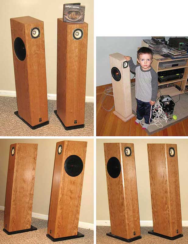
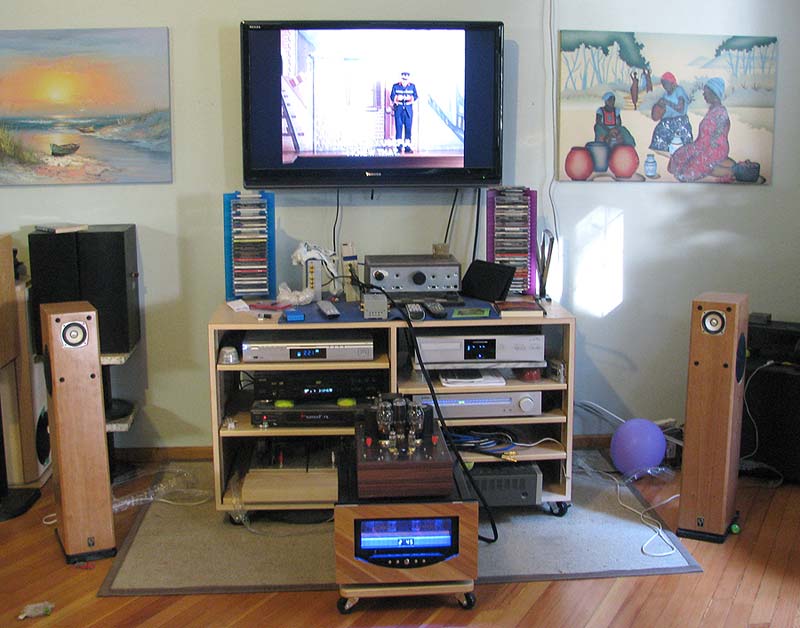
OK guys, thinking hats on, because, since the idea's recently come up again, I think it's about time we revisited this design and figured out why this monster TQWT simulates so poorly, yet usually performs well in-room -far better than conventionally accepted wisdom would suggest. I admit I have a liking for this box -I built a rough pair in response to a challenge from Terry a few months ago using the FE166E, and they worked pretty well -in fact, astonishingly so, considering all the apparant anomolies. We're looking at a driver ill-suited for TL loading with a low Q, a pipe with an So of 0 (so a theoretically high F3), and open at the other end, which isn't going to provide much any damping, and a driver position that seemingly dictates a massive hole circa 100Hz.

But it's never as bad as that. There's usually a dip at 100Hz[ish] but ony around 4 db in my experience. I got 28Hz loud and clear from the boxes I built -lower than the model says it should go. And while there's ripple, again, it's never as bad as predicted. So what's going on? Clearly, it's not the fault of Martin's software: his MathCad worksheets don't lie, though they don't take room-gain into account. So it must be what we (or I!) am / are inputting into them.

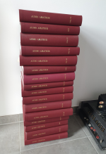
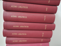
I understand that this is basically a Fostex factory design from their craft handbooks, which seem to be unavailable, or almost impossible to get hold of -anyone got them, and if so, could you send me an email? How is this thing it sized? I suspect / assume the line length is set to roughly 1/2 the wavelength of the Fs of the driver, but what about everything else? It's a pre Martin design, but what methodology, and how can we figure it out? Whatever it is, I suspect it's quite basic; perhpas it's a case of I can't see the wood for the trees.

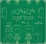
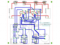
That internal baffle particularly interests me for example. Terry's original is 14" deep, yes? Subtract 1 1/2" for the front and rear walls to give us 12 1/2". Now, unless I'm confusing things here (I'm not at my best at the moment, so if I make a stupid error do let me know), I understand that it finishes 5 1/2" from the base, and 5 1/2" from the rear wall. But half of 12 1/2" is not 5 1/2", so surely the expansion of this taper is not constant? If you look carefully at his CAD drawing, it doesn't even look it. It almost seems to be two differentaially tuned pipes, one like a Voigt pipe with a rear vent, venting into a second pipe with different proportions. Thoughts?

Terry commented to me that the FE166E is a great match, and I can't deny it worked pretty well (and I like a warm ballance, believe me), the FE168ESigma is even better, but a friend (you around Dan?) mentioned that in a discussion with Terry shortly afterward, he also suggested the best bet would be a higher Q driver like the FF165K -I assume he's referiing to its 10.92 Qes, because Qts is down at 0.2 which is the lowest of all the Fostex 6" drivers.

Any thoughts and coments are welcome!

Best
Scott

60 Hz Hum/Buzz Only When RCA Inputs Connected - Yamaha A760

Heeelp!

Don't ask me why—it's a very long story—but I need a working Yamaha A760 amplifier. So far I've bought 3, and spent a fortune on refurb jobs by local techs that work on vintage gear. One of these techs has now passed away, and I want to avoid bringing things back to the other two shops because they've kept machines for over a year before!

I currently have one that works perfectly except for one thing: there's a hum/buzz on the speakers whenever any line level RCA input/output is plugged in to the machine.

I'm in North America, and the fundamental frequency of the hum seems to be 60Hz, with higher frequency noise harmonics, so this seems to be an AC grounding issue between the amp and other components. The noise is relatively quiet and stays the same volume regardless of where the volume control's at, but it seems to cause slight distortion in the audio signal.

When everything is unplugged from the line level input board, the hum disappears. There's no hum if just the speakers, turntable RCAs (and turntable ground wire) are connected. There is also no hum if the device plugged into the line level RCA board is not running on AC, like if it's an iPod running on battery. The RCA cables I have are decently shielded, and there is no hum problem on my other A760 amplifiers when I plug the same devices/cables in. (Those amps just have other problems I can't fix.)

While working on a prior A760 of mine with no hum issue, one tech told me there was a grounding problem with the chassis and he soldered a wire between the ground rail of the RCA inputs, the input switches and the chassis to correct it. So I used a multimeter to test continuity and resistance between the RCA ground and the chassis on this current unit. I assumed there may be oxidation in the chassis or a failing solder joint somewhere on a circuit board but there's good continuity for all RCA plugs to the chassis.

So I put this out to the community...what else could be going on here? Is there a specific component that may have begun to fail, and how can I test for that myself with a multimeter?

A few components have already been replaced, but I don't think the power supply in it has been touched. I know these machines have a weird "X" power supply, so maybe something's gone bad in that.

I tried testing the grounding of the two pairs of filter capacitors but finding the negative pin became confusing as they seem to be wired in series on the board and I'm not sure about discharging them etc.

(It may sound like I know what I'm doing but I've just done a lot of googling. I'm new to using a multimeter and not great at soldering so very simple instructions without abbreviated techy words would be best!)

Universal Tiger

In the late 70s, my friends and I assembled 3 "Universal Tiger" amplifiers degigned by Dan Mayer and sold by SWTPC.

After a couple months of operation, they all blew their output transisters. Recently I was browsing Dr. Leach's site and read his comments regarding the design."These amplifiers were very unstable, causing them to oscillate, overheat, and blow tweeters."

I find all this strange as, at the time, the Hirsch-Houck Labs gave the amplifier very high marks for sound quality and stability

Have you experts ever looked at the schematic to determine what could have caused the problem and how it can be resolved?

I would appreciate your comments.

I attach a copy of the schematic.

Attachments

  • universal tiger.gif
    universal tiger.gif
    33.8 KB · Views: 6,910

Scan-Speak D2905/9000 and 18W/8545

SOLD

NOS unused Scan Speak D2905/9000 and 18W/8545 My dad bought them years ago to build ACI Jaguars, and never did.

Let's get these to a home where they will be used. 🙂

$375 + shipping.

IMG_6098.jpeg

IMG_6104.jpeg

Attachments

  • IMG_6097.jpeg
    IMG_6097.jpeg
    815.5 KB · Views: 86
  • IMG_6103.jpeg
    IMG_6103.jpeg
    606.2 KB · Views: 96
  • IMG_6102.jpeg
    IMG_6102.jpeg
    626.8 KB · Views: 94
  • IMG_6101.jpeg
    IMG_6101.jpeg
    746.1 KB · Views: 86
  • IMG_6100.jpeg
    IMG_6100.jpeg
    691.2 KB · Views: 87
  • IMG_6099.jpeg
    IMG_6099.jpeg
    737.6 KB · Views: 64

Is this the correct way to power the filament of a 12AU7 with 6.3V

I am using a regulated power supply based on an LM317 to provide 6.3V DC for heating the filament of a 12AU7 tube.

Currently, I have wired it as follows:

  • Pin 4 and Pin 5 together → +6.3V
  • Pin 9 → GND (ground of the regulated power supply)
My question is: Is this the correct way to connect the filament in a 6.3V configuration?

I would appreciate any confirmation or suggestions to improve the connection. Additionally, should I consider anything else to minimize noise or extend tube life?

1742146842071.png

For Sale A pair Fostex FT17H super tweeters with custom bracket mount

A pair of Fostex FT17H super tweeters for sale, one has a small chip in housing but still functions see pictures. Used with a pair BLH with full range speakers. Bracket is aluminum angle brackets machined for the tweeters and are solid. Has wire tie on back for wire tie down. Asking $95.00 Shipping paid by purchaser to lower 48 states

Attachments

  • IMG_1096.jpeg
    IMG_1096.jpeg
    511.7 KB · Views: 50
  • IMG_1095.jpeg
    IMG_1095.jpeg
    554.9 KB · Views: 51
  • IMG_1094.jpeg
    IMG_1094.jpeg
    980.2 KB · Views: 46
  • IMG_1093.jpeg
    IMG_1093.jpeg
    1 MB · Views: 51

Hiss in Pioneer receiver

Hi all, I have an old Pioneer VSX-D1S receiver and am trying to hunt down the source of hiss.

When using any source input with playback on pause or disconnected, and using Direct Mode, there is no hiss until I crank the volume knob knob past 22. (I'm okay with that)
However, when using non-direct mode (again using any disconnected source input or playback paused), there is audible hiss when I turn the volume past 12. The hiss behavior is the same on Front, Rear, and Center speaker outputs, using none or any of the Dolby modes.

When I disconnect the DSP/DAC boards from the system, both Direct Mode and non-direct Mode have no hiss until I crank the volume past 22. I think this means the problem is in the DSP/DAC boards, or maybe these assemblies' upstream power supplies/regulators?
I re-capped most of the electrolytics on these two boards, and replaced the voltage regulators on these boards, but want to diagnose further before I buy other components.

The other thing I wonder is if the DSP/DAC needs to be adjusted (there are some variable resistors to adjust per the service manual), but I do not completely understand the equipment needs or what output to look for. Instructions in the service manual call for a noise meter, and an oscilliscope. I have an entry level oscilliscope; is that enough to try adjusting? It seems like these are the steps most closely related to minimizing hiss?
DSP_adjust_steps.png


Schematics and service manual can be found at https://www.manualslib.com/manual/1123277/Pioneer-Vsx-D1s.html

Any help would be greatly appreciated!

JLCPCB website problems 09/24

Have been unable to use the website properly since trying to upload some files this weekend. It keeps flitting about and won't upload a file. Gets to the infamous 96% and stops.
Don't seem to be able to ask the online support either.
Anyone having any issues. This on an android phone. Have tried different browsers.
Get all these errors come up.
Cheers

Attachments

  • Screenshot_2024-09-03-10-23-50-75_df198e732186825c8df26e3c5a10d7cd.jpg
    Screenshot_2024-09-03-10-23-50-75_df198e732186825c8df26e3c5a10d7cd.jpg
    160.6 KB · Views: 76
  • Screenshot_2024-09-03-10-23-00-67_df198e732186825c8df26e3c5a10d7cd.jpg
    Screenshot_2024-09-03-10-23-00-67_df198e732186825c8df26e3c5a10d7cd.jpg
    157.7 KB · Views: 76

BMS 12N630 or SB ACOUSTICS SB34NRXL75-8 ?

Hello All !
I would like to build a 3 Ways with a 12" Bass driver for HiFi use. I see two options BMS 12N630 and SB ACOUSTICS SB34NRXL75-8. The crossover frequency should be 200/300Hz.
A lot of positive review about the SB Acoustics but nothing about the BMS 12N630.
On paper they have the same performance in a bass reflex enclosure.
Someone here have listened the two woofers ?

DIY Headphone out. Do-able?

[Think I've got this in the right place, admins please move or delete if wrong.]

This is something ive been thinking about for a while now as my amp has no headphone socket. Then i rencently saw this video and thought maybe this could work:

Login to view embedded media
My problem is that i dont want to risk blowing my headphones up by forgetting to turn the volume down before plugging them in by using resistors but then didnt want resistors before the jack as that would affect the output to the speakers. So i came up with a practical solution (i think) where i use a 6PDT switch to go from speakers to headphones which lets me isolate the resistors to only the headphone jack.

Does this make sense? What resistors should i use and where would i place them? See dodgy diagram for what im thinking of doing.
Any feedback or help is greatly appreciated.
Amp is a Cambridge Audio A5, headphones are Bose Quietcomfort 15
1000036978.jpg

Someone need good RCA or XLR cable

For sale two pairs of cable. One pair of rca cable and one pair of xlr cable in 0,6m lenght.
Inakustik 1302 is verry good hifi cable from german company that sell verry good sounding cable. Look for positive test online. The sound is neutral with little of warmth. Bouth pairs are like new in original packing. If interest plese contact me. Price for one pair is 100 eu plus shipping. New costs around 300 eu/pair.

Attachments

  • IMG_20250122_194635.jpg
    IMG_20250122_194635.jpg
    505.9 KB · Views: 125
  • IMG_20250122_194642.jpg
    IMG_20250122_194642.jpg
    351.6 KB · Views: 122
  • IMG_20250122_194646.jpg
    IMG_20250122_194646.jpg
    317 KB · Views: 93
  • IMG_20250122_194655.jpg
    IMG_20250122_194655.jpg
    582.5 KB · Views: 113

Ampzilla Outputs Using MJ15022

I am finally getting around to fixing one of my Ampzilla amps (not the Ampzilla II or Son...the original). I had the -75V supply wire that runs to the edge of the board wear away and short itself out against a sharper edge of the output board solder connections. Strange. I guess it was close for years and vibration from the fan caused it? No clue. From the short, it blew up outputs and diodes on one channel. Got it fixed, but used parts on hand that were not the right transistors (used 2N5883 & 2N5885). They are lower voltage devices, so just used my variac to bring it up enough to make sure everything was stable and working.

Now I need outputs. Did some trading with another member here and got a set of original GAS101 & GAS102 outputs. Took the amp apart today and found out someone used NTE parts on the other channel. Question, if I can't get another set of GAS101 & GAS102 for the NTE channel, should I just order MJ15022 & 23 devices? If so, how closely matched are they. I really don't feel like buying a bunch at $7 each to match. Are they close enough for me to be happy and the amp to be stable if I order what I need?

Open to suggestions. Thanks!

Speakerbench - measurements quality issue

Hi all

I have recently started the jurney of making impedance measurements on drivers. I am using REW with Focusrite Scarlett 2i2 audio interface. I have Keysight lab calibrated DMM and a two digit precision scale.
Rsense is 99.32ohm. I am running the driver on a small amplifier.
I have made several measurements with success and can generate T/S parameters in REW. I am however after reading V. Dickasons Loudspeaker cookbook v8 interested in using Speakerbench and their advanced parameters method.
I succeeded in uploading the zma files and create a Json container. But the data seems to have an error - it says there is an issue with the quality. Can you guide me on what i am doing wrong?

Measurements in REW
Screenshot 2025-03-14 230227.png

Imported into Speakerbench - Quality issue :/
Screenshot 2025-03-13 222801.png

The wierd thing is that if i chose the Z measurements, they seems to be imported correct
Screenshot 2025-03-13 222922.png

A thread for Tysen and variations on WAW / FAST

A post of this picture of Tysen elicited a large number of requests for more information. So in aid of saving me from answering individual questions multiple times, let;s see if we can cover it here.

Tysen-comp.jpg


Tysen (named after our godson in the picture) is a Fostex FF85K & a CSS SDX7 (in both cases my fully modified version).

I chose sealed for the SDX7 because it works well sealed and with a bit of EQ can reach into the 25-30 Hz range in room. Tysen is 17 litres, but anywhere 14-21 litres net (including effect of stuffing).

The FF85KeN is in an aperiodically damped 10:1 taper TL. I wanted to tune the TL as low as i could withing the limited space i had available, Damping starts out really light getting increasingly dense towards the terminus (i call this arrangement a midTL).

Because of the efficiency of the SDX7 is lower than needed for a passive XO, and because it is so much easier, the system is active (biamped).

Tysen-inRoom.jpg


Chris & i are very pleased with how these turned out, and everyone who has heard them has been favourably impressed. First public exposure was on the Sunday of last years' VI diyFEST.

dave
  • Like
Reactions: wchang

Best Mean Well PS for TPA3255 amp(s)

I have read a lot of threads so forgive me if I missed seeing answers to these questions.

As time and budget permits I want to build some higher end mono, will try stereo for the mains at first, D class amps but for now looking into just buying a ZA3 without PS and using a Mean Well I can later use, or not, hopefully so, in building higher end amps.

I will eventually want at least 4 mono channels, maybe more and look into DIY PS's as well.

For now using the ZA3 in stereo, upgraded op amps, balanced line out, looking at these PS units.

Mean Well
HRP 450-48
HRP 600-48

I have seen where at least one seemingly knowledgeable user, on another forum, preferred the Mean Well HRP 450-36 as said the amp cleaner on the lower voltage.

I have seen here on the XRK 3255 thread where one member plans to use a different MW, I do not know why or if it is better or not.

Any help here would be greatly appreciated, been without a good system during our remodeling so going to dig out some older KEF line arrays I had in our long sold Toy Hauler and figure out a little sub setup.

Thanks!
Rick

For Sale TDA1541, DF1700P, SM5842AP, YM3623B

Hi,

I have accumulated digital filters, DAC, S/PDIF receiver ICs which not going to use.
These either bought together with DAC chips or desoldered from old CD players.

Full list
1. TDA1541 + SAA7220P/A - Desoldered from Phillips CD player, 80 USD
2. TDA1541 + SAA7220P/A - Desoldered from Phillips CD player, 80 USD
3. SM5842AP - Desoldered, 60 USD
4. Pair of ISO150AP - Desoldered, 30 USD
5. YM3623B - 10 USD
6. DF1700P - 30 USD

Open for reaonable offers.

Attachments

  • photo_2024-11-30_21-57-26.jpg
    photo_2024-11-30_21-57-26.jpg
    267.8 KB · Views: 203

Advice needed for pre amp power supply unit

Dear people,

I'm looking for (build in) pre amplifier for a LM3886 chip amp, see pictures below. The amp is powersupplied by a Toroidal Transformer 230v - 2 x 25v 6A. The amp sounds nice but I miss bass and power.
Anyway, I ordered this pre amp board by Dollatek. It fits the 47K Ohm values the amp needs. But now I need a dual 12v up tp 20v AC psu/transformer/voltage regulator. Can anybody advice me? Can I branche power for the toroidal? Do I need a second smaller transformer? I worry about possible hum.


71RxuvGXI+L._SL1000_.jpg


S7261f73a14f74d9bbbc9ddcdb8b0a1ddG.png


Sc5325a5d9bad4dc7b3c6dfb721c63434M.png

Bob Cordell’s BC-1 audio power amp

Hello,
This thread is created to discuss the BC-1 amplifier design and implementation as described in chapter 4 of Bob’s 2nd edition of the “Designing Audio Power Amplifiers” book.

We decided to put BC-1 in a hifi2000 Dissipante 3Ux300mm chassis as a means to have a complete design and as I put it, a reference design right down to the finest of details to make the build as easy as possible. It was done this way since it involves mechanical work such as heatsink drill and tapping that could be done by the chassis mfg as an additional cost if required.
The pcbs were designed to fit on the heatsinks and that chassis with a base pan.
The pcb set has mirror images pcbs for those heatsinks mounted on left and right sides.
As a beta tester I was hoping that you would review my build guides and assembly procedures for that chassis build.
Not to say that the design can’t be put in a different chassis but it was optimized and laid out for that particular chassis. Which means you will probably be on your own for mechanicals in a different chassis.
Still interested?
When I get on the computer I can show a few pics of the completed design

Attachments

  • IMG_0844.JPG
    IMG_0844.JPG
    560.7 KB · Views: 1,788
  • IMG_0845.JPG
    IMG_0845.JPG
    457.4 KB · Views: 1,568
  • IMG_0846.JPG
    IMG_0846.JPG
    407 KB · Views: 1,739
  • BC-1 Assembled pcbs-2.JPG
    BC-1 Assembled pcbs-2.JPG
    415.6 KB · Views: 1,721
  • BC-1 Assembled pcbs-6.JPG
    BC-1 Assembled pcbs-6.JPG
    483.1 KB · Views: 1,669
  • BC1 Schematic - Rick.asc
    BC1 Schematic - Rick.asc
    21.9 KB · Views: 590
  • BC1 Schematic - Rick.pdf
    BC1 Schematic - Rick.pdf
    45.4 KB · Views: 1,093

For Sale Pair of Hammond 1638 SAE output transformers, less than 500 hours use.

I purchased these 10K impedance OPT's to get a Wyetech 572-10 amp back up and running. One of the original 10K Audio Note OPT's was bad. I installed the Hammond's and was greatly enjoying the music these made, very close to what the OEM audio note OPT created. Then I discovered the 572-10 tube runs better with a lower impedance OPT. So I then purchased a pair of Hammond 1629 SAE OPT's, 6.5k ohm impedance. I installed these and yes the amp sounds better with these 6.5K OPT's and measures better as well.

These1638 SAE OPT's (10k ohm impedance) have less than 500 hours on them. Leads were never shortened, although I did crip some copper ring connectors to the output side as my amp uses an impedance switch. I even have the mfg. box they were shipped to me in.

Asking $310.00 for the pair and actual shipping cost. I am in Knoxville, TN.

Attachments

  • 1638SAE label.jpg
    1638SAE label.jpg
    437.6 KB · Views: 102
  • 1638 top.jpg
    1638 top.jpg
    445.5 KB · Views: 90
  • 1638 front bell cvr.jpg
    1638 front bell cvr.jpg
    473.6 KB · Views: 89

SEOS Waveguides different dimensions

I'm a little confused about the different dimensions of the various SEOS waveguides, the SEOS-18 with the 1.5 or 1.4 inch throats in particular.

Why are the dimensions of these two different than all of the others? They’re deeper than the 1” version (which is counter intuitive to me) and taller as well. But if we go up in size with the 22 and 24 the dimensions are similar to the 12 and 15 again and with the 22 in particular the dimensions are the same for all throat sizes, just a little deeper for smaller throats (which is what I would expect). So why are the large throat SEOS-18 different from all the other ones?

I'm basing this on the data provided by the polish manufacturer.

Diode bridge as loop breaker question

Hi!
After a serious grunding noise problem with a tubepreamp and the SEWA mosfet follower amp I was re-reading all my articles about earthing and I found something mistakable thing with the diode bridge coupling.

Mr. Pass wrote in the ZV4 docs:

Note in Figure 6 that we have chosen to isolate
the two channels through a rectifier bridge to ground, with each
channel’s ground appearing on one of the AC legs of the bridge.
As it is in the attached image.

Mr. Rod Elliot wrote:

Note the way the bridge is wired, with the two AC terminals shorted, and the two DC terminals shorted. Other connection possibilities are dangerous, and must be avoided.
as it is in the next attached image.

Now I have only one question:

How should I connect the diode bridge to the circuit grund?

DC legs to Earth - AC legs to the circuit? Nelson Pass
AC legs to Earth - DC legs to the circuit? Rod Elliot

So, Who has true?????????????????????????????

Greets:

Tyimo

Attachments

  • psu ground.jpg
    psu ground.jpg
    42.5 KB · Views: 3,256

Nelson Pass AB100

I have 2 channels on a solid aluminium plate on offer. Built with good components and Sanken 2SB1560/2SD2390 output transistors on Prasi pcbs. The boards are ready to use and set to 270mA at +/-35V. The DC offset is below 10mV after warm-up. The aluminium plate has 3 M5 threaded holes on both long sides, prepared for heat sink mounting. At low output power, the aluminium plate is sufficient for cooling if it is positioned vertically.
I would like €130 + shipping for it. The weight is 3kg, shipping from Germany.
WhatsApp Bild 2025-03-16 um 09.53.40_bdc36fb1.jpg
WhatsApp Bild 2025-03-16 um 09.53.40_4e1e25a7.jpg

WhatsApp Bild 2025-03-16 um 09.53.40_7235f4c0.jpg

WhatsApp Bild 2025-03-16 um 09.53.40_d2aece85.jpg

2025 Pass JFET Beast speculations

Speculations about Pass JFET Beast R2 disclosed in another thread.

It looks like only 1 resistor per JFET cell. That causes me to think that one JFET is the current source and the other JFET is the buffer. It is a single-ended buffer.

My guess is that all JFETs are J113.

Wild guess is 7mA idle current per buffer cell.

If I counted correctly, there are 560 JFETs on each PCB.

My guess is around 22 watts per channel just before clipping of the current source.

I am thinking of similar sized build for a project but the buffer cell will be the J113 Cirlcotron from EUVL. I constructed one such cell and it works great and has 2x current capability of idle. The downside is many more resistors than a single ended cell and 2 extra power supplies per channel. I like to build something that is not a clone.

2025_Pass_JFET_Beast.jpg
2025_Pass_JFET_Beast2.jpg
2025_Pass_Beast_calc.jpg

r70xa headphone amp design

Hello! I am trying to design some schematics for my r70xa. I have some tubes on hand and was thinking of doing a push pull OTL, since I will need some good drive for these headphones having an impedance of 470ohm. I have some tubes on hand already. Most of the ones that I have are: 12AU7, 6AU6, 6AU8, 6AU6A, 6AU8A, 6BA6, 6AW8A, 6BA8A, 6BC4, 6BC5, 6BC8, 6BD6. I know a lot of these are mainly used in TVs, so don't know if they would work in an audio project. Maybe I could use any of these as drivers and buy output tubes? Any thoughts appreciated, thanks for looking.
  • Like
Reactions: lineup

Rauch P-120 Hum Fixed

I have four of these amplifiers and they all exhibit hum on output regardless of output level even with nothing connected. The hum is actually quite loud and annoying. I believe this could be a design fault with these amplifiers?

IMG20250316095240.jpg

Thanks to Bonsai I have completely eliminated the hum even with headphones on the output.

First I cut the track on the 0v line between the smoothing caps and experimented adding a 1ohm HBR between the 0v smoothing caps and the ground 'amplifier module' this reduced the hum slightly but hiss and DC offset increased. Reducing the resistance to 0.8ohms 'struck a balance' Higher values made it much worse.

IMG20250316085302.jpg

Then I noticed that the speaker return wires are connected to chassis ground via a approx 8ohm resistor and cap. Also connected to this is earth mains. (resistor on top right of 1st pic)

IMG20250316085444.jpg

IMG20241201111603.jpg

I removed the black speaker return wires from the board and connected them to the 0v smoothing caps. Hum completely gone! Maybe I should restore the cut track with the 0.8ohn resistors?

IMG20250316094223.jpg
  • Like
Reactions: huggygood

Service & User Manuals for Rek-O-Kut B12H?

Hi!
Glad to find this website - what a great place! 🙂
First post here and it's about trying to find the service- and user manuals for the Rek-O-Kut B12H.
Haven't had any luck at Vinyl Engine or any other place.
Any chance that somebody here could point me in the right direction please?
The B12H is one of my all-time favourite turntables 😀👍
Peter

SB Acoustics Satori MW13P-8 5" Egyptian Papyrus Cone Woofer

I have for sale this two SB Acoustics Satori MW13P-8 5" Egyptian Papyrus Cone Woofers.
I bougth them like there where new, one year ago from a diyaudio felow.
Last week i tested them with dats before try them and one of the woofers had higher dc resistence than the other around 10ohms and i found that strange. After a couple of tries it stopped to work and don't have sound.
So i will sell both for 125€ shipping in Europe included. The buyer should repair one of the woofers. Unfortunaly i don't know where to repair it and i don't want to proceed with the project i intended for them.

Attachments

  • 20250316_074720.jpg
    20250316_074720.jpg
    374 KB · Views: 38
  • 20250316_074725.jpg
    20250316_074725.jpg
    276.5 KB · Views: 38
  • 20250316_074735.jpg
    20250316_074735.jpg
    471.1 KB · Views: 39
  • 20250316_074748.jpg
    20250316_074748.jpg
    487.4 KB · Views: 38
  • 20250316_074759.jpg
    20250316_074759.jpg
    315.2 KB · Views: 38
  • 20250316_074809.jpg
    20250316_074809.jpg
    304.1 KB · Views: 36

HELP - Adding digital input to CD player

Hi everyone, first of all, I'm a strong enthusiast, not a technician or engineer.
I have a hi-end CD player with an excelent DAC and analog section. It's a really fantantic CD player, very silent, dynamic with excelent detail.
I would love to know if it's possible to add a digital INPUT to it. So I can use the DAC and analog section by connecting an external digital transport (SPDIF).

I have a digital input I2S module but I don't know if it's usable here. You can see the attached photo of that module.
I'm also posting the schematic of the digital section of the CD player and the DAC (just one channel).
Any help or input would be much apreciated!

Thanks and greetings from Lisbon
Andre

Attachments

  • IMG_5184.JPG
    IMG_5184.JPG
    428.2 KB · Views: 106
  • Digital section2.jpg
    Digital section2.jpg
    186.8 KB · Views: 104
  • DAC_page-0001.jpg
    DAC_page-0001.jpg
    129.2 KB · Views: 99
  • Like
Reactions: Miller-8

Rotel RC-980BX OPamps

I have a Rotel RC-980bx preamp and am attempting to upgrade the 2 AD711JN opamps, all the caps seem to be Black Gate Rubycons, so will leave those as they are. I plan on installing 8 pin sockets to be able to replace the opamps for listening comparison.

The ic501 and ic502 are the AD711JN. What opamps would be a drop in replacement.

Any help would be appreciated.

Thomas

Tube-I-zator Professional PCB

Hi to all,

Because of the big success of the I/V SRPP Tube Stage in my finished 4x TDA1541A DAC,
i am planning a PCB Group Buy for those who want to have a optical and technical perfect solution (minimum pre-order 20 PCB´s).
This PCB is for "I-OUT" DAC´s with unbalanced output.
If you want to use it with a "V-OUT" DAC, you must insert a capacitor between the DAC and the PCB.

I have added my Heater-Switch Circuit to the PCB.
Now everyone is able to change between the Russian (6N1P, 6N2P ect.) and Western (12AX7, ECC83 ect.) pinout, without soldering.

The Anode and Heater PSU is included.
There will be the possibility to use an external Anode-PSU, e.g. for upgrading with a Tube rectifier.
Furthermore i made the Audio-Lines extra wide (1,5mm) and choose 70µm copper to get minimal loss.

It will be a 2-Layer Design to seaprate the Audio-Lines (Bottom Layer) from the Electrical-Lines (Top-Layer).


The new Tube-I-zator V3.1

The evolution brings the following changes:

- Anode PSU with Salas SSHV Shunt Reg. onboard
- External B+ Input for usage with other Anode PSU
- Heater PSU with C-R-C filtering
- Heater PSU with Softstart circuit
- Heater PSU Power LED
- Design failures corrected

Thanks to John (-ecdesigns-) for the following suggestions!

- Grid stoppers to prevent unwanted oscillations
- Bias current injection for TDA1541A usage
- Pull-down resistors to keep the coupling cap output at GND-potential

Still on the Module:

- Heater switch for 6N2P or 12AX7 usage


New version 3

You will find the BOM in my blog HERE!

For orders please send me a PM or a mail to diyaudiopcb (at) gmx.com


Best regards to the community
dvb-projekt

:wave:

Attachments

  • tubeizatorb.jpg
    tubeizatorb.jpg
    453.4 KB · Views: 11,612
  • tubeizatorwithheaterswi.png
    tubeizatorwithheaterswi.png
    28.1 KB · Views: 11,741

41 years of Audio Amateur issues - what's it worth?

Cleaning up my office, unearthed my collection of bound Audio Amateur issues. Fully complete from the inaugural issue 1, 1970 to the last issue 4, 2011 under the lead of Ed Dell. Not a single one missing.
I put this together when AA's founder Ed Dell retired and first Elektor and then AudioXpress took over.
I'm thinking of putting it up for sale, but what would this be worth?
What do you guys think? Should I keep it?

Jan

Attachments

  • AA volumes 1.png
    AA volumes 1.png
    689.1 KB · Views: 73
  • AA volumes 2.png
    AA volumes 2.png
    2 MB · Views: 69
  • Like
Reactions: Stefano and Vix

12AU7 preamplifier project W/ Mullard Tubes & Mundorf Caps

For Sale: 12AU7 Tube Preamplifier (Conrad Johnson PV-12L Inspired)

The design is inspired by the renowned Conrad Johnson PV-12L, known for its superior audio performance and musicality. There are some differences between the original design and this kit from Across Audio, but the design is well executed. The PCB and components are good quality, still I did see the need to upgrade a few things.

Key Features & Upgrades:

  • Tubes: (2x matched) Mullard 12AU7 tubes, manufactured in Russia, delivering a smooth, rich sound signature with excellent performance.
  • Coupling Capacitors:
    • (2x matched) Mundorf MCap Supreme EVO Aluminum Oil 3.3µF 800VDC output coupling capacitors, known for their high-fidelity sound and exceptional durability.
    • (2x matched) Cornell Dubilier 940C 1.5µF 1600VDC capacitors (output coupling and bypass), offering reliable performance and enhancing sonic clarity.
  • Bulk Capacitor: (1x) JJ 100M + 100M 500V capacitor, providing stable power filtration for improved signal integrity.
This preamplifier is the foundation for a great build and I would certainly finish it myself, but I'm already happy with my mono 6SN7/6Y6G and only have room for 1 speaker in my tiny NY apartment. All proceeds will go to buying more records and a better phono cartridge 🙂

Condition: Excellent. Fully assembled, tested, and project ready. Ships securely, carefully packaged. Shipping Via USPS Ground Advantage®, or other carrier of your choice.

Dimensions:

Height: 3.5" (with components) / 89mm
Width: 4.25" / 108mm
Length: 9" / 229mm

Voltage Requirements:
  • AC1 (Plate Voltage): 0-AC280V (0.1A)
  • AC2 (Heater Filament): 0-AC9V (2.5A)
  • AC3 (Power-On Delay): 0-AC8V (0.5A)
Recommended power transformer:

SaNzia 55W Home Audio EI Type Power Transformer

IMG_0817.JPG


IMG_0828.JPG

IMG_0813.JPG

Cronus - It's about time.

Hi Folks,

You can find it here:
Cronus Reclocking

Cronus is a module designed for providing clocks to and reclocking output from digital sources. Cronus forms the backbone for audio sources built around 2 other module types - Hermes and Rhea.

Cronus was a long time coming - because we worked hard to make the results not just good - but superb. We could have released earlier - but we wanted to get in all of the things we desired after two prototypes.

Special thanks to Miero for his beta testing.

Extra special thanks to Brian for being patient with my long design process - and for putting together awesome beta and production kits.

Cronus provides the following:

  • An ultra low noise low impedance 3.3V power supply for clocks and reclocking section.
  • A clock selection multiplexer to switch between 44.1 and 48Khz time bases.
  • A selectable/bypassable ultra low phase noise clock divider to supply 1:2 or 1:4 clocks to a source.
  • A synchronous reclocker that re-clocks the audio from the source back to the master clock. This brings all signals back into alignment with the actual master clock regardless of source jitter - thus your final signal is as good as the clock you supply - which is to say - excellent!
  • Pads for pluggable clock sockets based on standard DIP(8 and 14) clock - See Rhea thread for more details.
  • An interface for connection to our isolation modules for various sources - See Hermes threads for more details. Hermes isolates your DAC completely from your source.
  • Interfaces for connecting to B3/B3SE and any other PCM/DSD DAC.
  • SMA and uFL connectors for external clock signals (both in or out)
  • uFL connectors for PCM/DSD output.

Some useful things to keep in mind:

The re-clocking section makes use of a Potato semi FlipFlop. When using a FF in this way the frequency of the clock input supplied to the FF must be at least 2 x any signal. For this reason ~22-24Mhz family clocks can be used for PCM signals up to 192Khz - for up to 384Khz you must double that. The device is capable of up to 768Khz PCM.

The module is designed for around ~5VDC input - but it is fine to go higher (absolute max is 16VDC) depending on the load you are putting on the VREG (adm7150) please refer to the datasheet about limits. The max current is listed at 800ma. The current consumption will vary depending on loads and audio frequencies. In testing using Crystek clocks (50Mhz family) I am drawing well under 150ma at 384khz. Keep in mind also that Hermes modules are designed to be powered on the clean side by the Cronus power supply.

The clocks are isolated from each-other and the rest of the circuit by utilizing L/C filtering with ferrites.

The Cronus is designed to work with Sources that provide a clock selection signal (CS) and can accept an external audio master clock - it is currently tested with two Hermes modules. Hermes-BBB for the BeagleBone black (using Botic distro), and the Hermes-Amanero for the Amanero USB module. There will be a thread for each. Both are tested and work up to 384Khz.

I will fill in more details to this post as necessary.

A manual is under way for each module - but I hope you basically know what you need right now. 🙂

The Hermes and Rhea threads will fill in a lot more detail.

I have also attached the pinouts of the .1" headers on the output side of the cronus and the Hermes header.

Note: If you use the terminal blocks - it is recommended to mount them on the bottom side so they don't interfere with uFL connectors etc.

Ask away!

Attachments

  • cronus.JPG
    cronus.JPG
    56.9 KB · Views: 6,327
  • Cronus_OUT.PNG
    Cronus_OUT.PNG
    24.1 KB · Views: 5,409
  • Hermes_pinout.PNG
    Hermes_pinout.PNG
    25.1 KB · Views: 5,357

NOS Genuine Toshiba 2SB554

Hi Guys: I have a few dozen 2sb554's. I do NOT have the complement 2sd424's. Just the PNP B554's. These are among the best sounding TO-3's. The MJ2119x series are close, but not as good.

Same batch in bulk packing. These came from an Adcom Warehouse when they closed ops in the USA several years ago. So they will match that era GFA555, 565, 585's very well.

$10 each. Min order Qty = 4

Ten or more $7.50 each. +shipping

I can trade 1:1 if you have 2sd424's NOS. If you have used, I will trade 1:2 for these new unused ones.

Currently shipping only to the USA.

Inventory left 30 pieces

Attachments

  • IMG_8617.jpeg
    IMG_8617.jpeg
    535 KB · Views: 34
  • IMG_8616.jpeg
    IMG_8616.jpeg
    623.6 KB · Views: 27
  • IMG_8615.jpeg
    IMG_8615.jpeg
    555.9 KB · Views: 38
  • IMG_8614.jpeg
    IMG_8614.jpeg
    587.5 KB · Views: 36

Sony HCD Shake X3 power supply repair

Hi

I have problem with SMPS from sony shi... device 😕

The first problem that I managed to find was a shorted one of the two MOSFETs marked K16A60W.
I replaced 2 of them with the same ones. They are located in the middle of the largest radiator on the board). I also replaced the main 10A fuse, but unfortunately it did not help.

While searching for faults, I reached the area marked with a red square.
The R39 resistor was burnt, but I could not read its value, and an interesting coincidence is the fact that the available service manual for this model does not contain a schematic diagram of the power supply... I put a 220 ohm resistor there, because I found this value in the catalog note of the ICE2PCS01 IC (PFC). In my region, I could not find the THT version, so I did the same in the SMD version.

After checking the entire area around the ICE2PCS01 IC (PFC), I did not find any damage and started the device using a 150W tungsten bulb. It didn't even have time to flash before I heard a crack. R39 flew again, and with it the ICE. I've run out of ideas and I don't know what to do next...

I checked all the elements that are near the ICE and even those outside the red square and I found nothing. The resistor values are ok, but there is one thing that puzzles me.
This is the first time I've noticed that there is a connection between the primary and secondary windings, as you can see in the last photo. I've repaired some SMPS, but I've never had a case like this before.

Please help.🙁


20250315_210420.jpg

20250315_165616.jpg

20250315_210957.jpg

20250315_210138.jpg

20250315_210145.jpg

20250315_210620.jpg

Attachments

Isophon speaker build - Help needed with crossover

Hi,
I got a pair of speakers years ago that consisted of Isophon drivers (P203s and P713), Mission cabinets, and a modern crossover that was made using the original inductors and all new resistors and caps. I'm making some new baffles for the drivers that will be placed in vintage cabinets.

However I have no experience with crossovers, and having drawn out the crossover circuit (inductor values unknown) I'm wondering if it was based on an old crossover circuit or is it a basketcase design. I can't find any 2 way designs that use this tweeter network. Is it a midrange filter?


Driver details:
https://www.hifi-archiv.info/Isophon/1961 Isophon Programm/08.jpg
https://www.hifi-archiv.info/Isophon/1961 Isophon Programm/06.jpg

Attachments

  • IMG_20240730_153922.jpg
    IMG_20240730_153922.jpg
    432 KB · Views: 191
  • IMG_20240730_154416.jpg
    IMG_20240730_154416.jpg
    518.2 KB · Views: 165
  • IMG_20240730_154434.jpg
    IMG_20240730_154434.jpg
    347.9 KB · Views: 133
  • IMG_20240730_154538.jpg
    IMG_20240730_154538.jpg
    305.1 KB · Views: 140

Right subwoofer for single ended triode amp and high efficiency Altec speakers

Hello. Question from Italy. I've got the smallest single ended triode from Line Magnetic, 3+3 watt mini 218ia, driving Altec Lansing coaxial speakers 409-8c, 97 db sensitivity, nominal impedance 8 ohm, minimum impedance 6 ohm.

The speakers sound fantastic but lack deep bass. I read on some forums that for a tube amp I need an active subwoofer with speaker level imputs, and I shoud preserve the "voice" of the tube amp connecting in parallel on the amp speaker terminals the speakers and the sub, in order for speakers and sub to overlap on the low frequencies.

Is that correct? If it is, I have found a used Yamaha YST-Sw45 in Italy at a good price. It is an active subwoofer and has speaker level imputs.

This is the online manual:

https://usa.yamaha.com/files/download/other_assets/2/319752/YST-SW45.pdf

Can any of you tell me what kind of impedance the tube amp will read if I connect in parallel on the amp's speaker terminals the Altec and the Yamaha YST-Sw45? For example, On the same amp's speaker terminal banana plug to the speakers and spades to the sub.

(I will not use the speaker level outputs on the sub, I will let overlap the bass from speakers and sub.)

Or, is there a safer way to connect tube amp and sub?


altec 409 7.jpg


altec 409 8.jpg

For Sale Free pair SB Acoustic mw19p1-8

Yes, these are free but free for a reason. I bought these used off eBay and stored them away for a project. When I started the process of taking inventory to start, I noticed some creasing around the outside of the cones. I think they experienced some over excursion and will not be perfect. I was thinking about using an edge treatment from Troels but decided to just buy another pair.

Just pay for shipping and I will ship these to you.

Attachments

  • image.jpg
    image.jpg
    1 MB · Views: 99
  • image.jpg
    image.jpg
    671.2 KB · Views: 101
  • Like
Reactions: vassilis1984

200Watt @ 4 Ohm Error Dumping Amp with ultra low distortion

This split-Mirror Diamond (sMD) amplifier is a bipolar multi-nested feedback amplifier designed using LTSpice. It is intended as a redesign and reconstruction on a Nakamichi PA-5 chassis that can support the numbers of output devices indicated with its +/- 60 Volt supplies. The amplifier uses two operational amplifiers, an LTC6090-5 high voltage input amplifier to provide voltage gain of ~14dB and an LT1022 amplifier with output tracking supplies that controls the diamond. The power output network uses multi-paralleled bipolar devices. These interact with 4 high current BIPOLAR devices Q1/Q2 as inputs and Q3/Q4 connected as diodes.

The input devices Q1/Q2 are fed from constant current sources by two power MOSFET’s M5 and M6 feeding about 90mA to the input side of the diamond. This current is mirrored in the output Q3/Q4 devices, being thermally connected to the input Q1/Q2 devices to support thermal tracking of the set point quiescent current. The dissipation is about 25 Watts idling/channel, hence not a low quiescent amplifier. Also included is a current limiting protection network that supports a 200W/4 Ohm load.

As a caveat it should be noted that many operational amplifiers are not modeled for distortion and that the total harmonic distortions numbers indicated are not trustworthy. Notwithstanding the realities the harmonic distortion spectral components simulated are all of amplitude beneath the noise floor for all power levels to 200W/4R at a more difficult frequency of 2kHz. In the screenshots the 0dB value represents 28.4 V RMS that supports 200W/4R or 100W/8R.

Again, I would like to thank Hans Polak for his help in using LTSpice and for his examination and input on the network design.

Attachments

  • Screen Shot 2025-03-09 at 3.15.38 PM.png
    Screen Shot 2025-03-09 at 3.15.38 PM.png
    891.4 KB · Views: 950

Rotel RB980 accident, how much do I need to replace?

I accidently slipped with the probe briefly connecting the negative rail to the base on Q621, collector on Q615 and emitter on Q609. The positive rail fuse blew as this happened. Changed the fuse but it blew as I powered up the amp.

Any insights as to what could have been damaged are very welcome.

Schematic below and the blue line is where the short happened and marking the positive rail fuse (T4).

RB980.JPG

WTB GlassWare Aikido rev. C octal build guide

I managed to buy this circuit board along with a build guide, but of course, I have misplaced it and I need it to complete the build. The board says Aikido Glassware 2007 rev C. and the board is meant to support 6SN7 tubes as one of the possible tubes that could be used in it. There are 4 tube sockets. and the board is green but that may not matter so much. Perhaps you have an old manual that you would part with for a few bucks for your time, or even make a copy.

Output tube distortion comparison

I have few different sets of output tubes and I perceived differences in sound so I measured the distortion under the same operating conditions. The amplifier is a PP UL with A431 style OPT, 470V B+, 15dB gNFB and the tubes biased for 20W each at idle. The graphs are distortion sweeps at 5W into a non-inductive 8ohm load. The %THD legends are measured at 1kHz.
JJ-6CA7.png
JJ-KT77.png
Sovtek-6550.png
GL-KT88.png
EH-KT90.png


Last of all I did the same test with a Firstwatt J2, 5W into a 8ohm non-inductive load

Firstwatt J2.png

Germanium investigations

After watching the NP interview where he discussed his interest in Germanium, I ordered some parts. The parts have begun to tricke in.

This is a 2SB63 power device. It looks to me to have a built-in compressor. Where a MOSFET is a square law device, this Germanium BJT looks like a 1/X law device.

Attachments

  • 2SB63_family.jpg
    2SB63_family.jpg
    75.6 KB · Views: 2,843
  • 2SB63_gain.jpg
    2SB63_gain.jpg
    93.6 KB · Views: 2,845

back to back power transformers

Hi,

I've been playing with very low power valve/tube amplifiers and I've used boost converters to generate 180V-240V DC. As I cannot get rid of the switching noise, I'm just going to try transformers (encapsulated = cheap).

The idea is to use two identical transformers back to back (240V to 2x6V). The transformers are rated 10VA and the output current is, ideally, around 830mA whereas the input current is around 40 mA.
The question is: after applying 6V to the secondary of the second transformer to get 240V again( in an ideal world), how much current, taking into account the losses, can I expect to have to supply the circuit?

After the transformer, I will use a silicon full wave rectifier made with diodes for both voltages.
For the heaters I will take the 6V, rectify it to obtain 8.4 DC and use a 7806 to apply 6V DC to the heaters of the valves. I will do the same for the HV output and then lower the voltage with resistors to get the voltages I want.

https://www.switchelectronics.co.uk/products/2-x-6v-10va-230v-encapsulated-pcb-transformer

Another option would be to go to toroidals, since they can deliver much higher current for an ok price.

https://www.switchelectronics.co.uk...06-toroidal-transformer-30va-0-6v-vigortronix

Kind regards,

Pedro
Projects by fanatics, for fanatics
Get answers and advice for everyone wanting to learn the art of audio.
Join the Community
507,757
Members
7,887,068
Messages

Filter

Forum Statistics

Threads
406,168
Messages
7,887,068
Members
507,757
Latest member
jossdorn