Hi!
After a serious grunding noise problem with a tubepreamp and the SEWA mosfet follower amp I was re-reading all my articles about earthing and I found something mistakable thing with the diode bridge coupling.
Mr. Pass wrote in the ZV4 docs:
Mr. Rod Elliot wrote:
Now I have only one question:
How should I connect the diode bridge to the circuit grund?
DC legs to Earth - AC legs to the circuit? Nelson Pass
AC legs to Earth - DC legs to the circuit? Rod Elliot
So, Who has true?????????????????????????????
Greets:
Tyimo
After a serious grunding noise problem with a tubepreamp and the SEWA mosfet follower amp I was re-reading all my articles about earthing and I found something mistakable thing with the diode bridge coupling.
Mr. Pass wrote in the ZV4 docs:
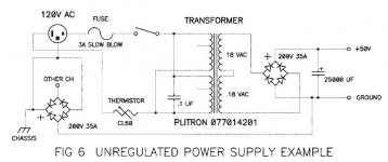
As it is in the attached image.Note in Figure 6 that we have chosen to isolate
the two channels through a rectifier bridge to ground, with each
channel’s ground appearing on one of the AC legs of the bridge.
Mr. Rod Elliot wrote:
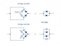
as it is in the next attached image.Note the way the bridge is wired, with the two AC terminals shorted, and the two DC terminals shorted. Other connection possibilities are dangerous, and must be avoided.
Now I have only one question:
How should I connect the diode bridge to the circuit grund?
DC legs to Earth - AC legs to the circuit? Nelson Pass
AC legs to Earth - DC legs to the circuit? Rod Elliot
So, Who has true?????????????????????????????
Greets:
Tyimo
Attachments
Tyimo said:DC legs to Earth - AC legs to the circuit? Nelson Pass
AC legs to Earth - DC legs to the circuit? Rod Elliot
So, Who has true?????????????????????????????
Both.

Hi Babowana!
Than why Rod Elliot wrote:
Tyimo
Than why Rod Elliot wrote:
?????Other connection possibilities are dangerous, and must be avoided.
Tyimo
Tyimo said:Than why Rod Elliot wrote:
?????
When he wrote that, he was unsure of himself . . . ?
I hope the attached sketches show the understanding.
The horizontal flip is always direction-free symmetry.
Either end of (+/-) or (~/~) could go the gnd.
Attachments
Nixie said:For a ground loop breaker, besides the diodes you should put a 5 to 20 ohm resistor in parallel, as well as a small cap as HF bypass (0.1-1 uf).
Why?
In most ground loop breakers I've seen, the diodes are there as protection in case of fault where the resistor would just burn out. It's the resistor that's doing the ground lifting--you just need sufficiently different resistances on each of the legs of the ground loop. If you just have diodes, the circuit ground is floating within the one diode drop from earth, with no connection to earth; with a low value resistor, I find it still breaks ground loops, but the circuit tends to stay closer to eart. The bypass capacitor allows earth to sink HF interference. With the scope I see less RF on the circuit ground when the cap is added.
Hi Nixie!
Thanks! Yes, I know. Rod Elliot wrote the same. Most of time a simple diode bridge (35A) or a thermistor (10R/5W) was enough for me.
Greets:
Tyimo
For a ground loop breaker, besides the diodes you should put a 5 to 20 ohm resistor in parallel, as well as a small cap as HF bypass (0.1-1 uf). Make sure the diodes are rated at sufficient current so that in a fault situation the fuse on the hot mains line blows!
Thanks! Yes, I know. Rod Elliot wrote the same. Most of time a simple diode bridge (35A) or a thermistor (10R/5W) was enough for me.
Greets:
Tyimo
Hi,
both ESP and Pass circuit are correct. But they are different and for different purposes.
The Pass circuit is a for a 2channel amplifier and isolates the two channels from each other thus breaking the ground loop and avoiding hum. The disadvantage is the 35A rating of the safety connection from audio ground to safety earth.
The ESP circuit is for a single channel amplifier and has the advantage of 35*2 =70A rating of the safety connection from audio ground to safety earth.
The additional capacitor and resistor can be added to either the ESP or Pass version of the circuit. They are effectively optional and may work better for some amplifiers/user's ancilliaries/house earthing than others. I tend to use the dual Power diode //cap//Power resistor for EACH channel. i.e. the ESP version. The Pass version is basically a money saving exercise.
AndrewT said:The Pass version is basically a money saving exercise.
I don't 100% agree.
Otherwise, he is no different from my another side, isn't he.
which part of omitting a full dual diode with //resistor//cap for each channel do you not 100% agree is money saving?Babowana said:I don't 100% agree.
Otherwise, he is no different from my another side, isn't he.
AndrewT said:The additional capacitor and resistor can be added to either the ESP or Pass version of the circuit. They are effectively optional and may work better for some amplifiers/user's ancilliaries/house earthing than others. I tend to use the dual Power diode //cap//Power resistor for EACH channel. i.e. the ESP version. The Pass version is basically a money saving exercise.
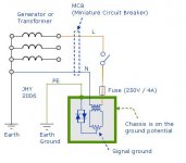
The paralleled diodes in the opposite direction each other are to break current between the signal star ground and the protective earth (connected to the chassis) – to break possible ground loop. Then, the signal star ground would not see the small signal noises coming through the ground loop. But, this works only when the potential difference between the signal star ground and the protective earth is less than about 650mV. When the potential is greater than this value, the diodes are shorted for current flow with no resistance, and the current will blow off the fuse installed at the entrance of the live (active) line or switch off the house wall breaker – for safety.
Enough is enough.
Your comments are just words to talk words, saying nothing about clear technical explanation. And, the last sentence is just a kinda bad mouthing.
Hi,
I see a far more onerous demand from those inverse parallel diodes.
The fault current that can pass prior to blowing a fuse is enormous.
A 25A or 35A power diode has a peak current rating in the hundreds of Amperes. A dual 25A or dual 35A has roughly twice as much capacity at peak rating. This should help the diodes to survive the many kA that can pass to earth in the few uS that it takes for the fuse to rupture and the arc to extinguish.
A single diode without a parallel cap and/or parallel power resistor for each channel is a cheaper option than the dual diode//Power resistor//cap. I believe that if us amateurs cannot extensively test what we assemble then when it comes to safety we should not take the risk of cutting corners nor costs.
The Pass system as shown is the cut price system. Whether it is adequate is arguable. The fact is,
The Pass version is basically a money saving exercise.
AndrewT said:I believe that if us amateurs cannot extensively test what we assemble then when it comes to safety we should not take the risk of cutting corners nor costs.
US amatures . . . LOL ~
<AndrewT>
The ESP circuit is for a single channel amplifier and has the advantage of 35*2 =70A rating of the safety connection from audio ground to safety earth.
A 25A or 35A power diode has a peak current rating in the hundreds of Amperes. A dual 25A or dual 35A has roughly twice as much capacity at peak rating. This should help the diodes to survive the many kA that can pass to earth in the few uS that it takes for the fuse to rupture and the arc to extinguish.
<AndrewT>
Two words from one mouth! LOL ~
I hope you are able to look into the attached concept.
Attachments
Nixie said:Same place you would normally earth your circuit.
Nice , considering most of the consumer electronics doesnt have an earth connection at all .
From the Pass V4 article it seems to me clear enough that a good role is to connect the earth bridge near the voltage rectifier bridge .
Usually, if I consider a phono preamp it is common sense to tie the 2 grounds of both channels together at the output and then from there to the chassis . ( they use to do that also in cd players ) .
The difference is in the potential of the chassis . Without an earth connection it can be at quite high-ac values .

- Home
- Amplifiers
- Pass Labs
- Diode bridge as loop breaker question