All scrap/trash subwoofer enclosure

Not a question, just something I attempted that came out really well.
I got a 15y/o 6.5" Samsung subwoofer from town trash. Orig enclosure was on its back in a puddle...not usable.
Not worth spending cash or even waste new plywood on. So I decided to try to make an enclosure out of left over scrap. That fits snuggle in my shelving unit.


I Used:
-24"x13" piece of sheathing plywood left over from fixing my roof.
-A 15" sqyare piece of 1/8" sanded plywood left from skinning my fish tank stand.
-the drawer from a child's maple night stand
-A childs floating bookshelf
-base is cut from heavy MDF kitchen cabinet toe kick/trim.
-scraps of left over 2"x4"s and 1"x3"s
-used left over paint from the bathroom
-used $1 store drywall screws (2.33¢ per screw, my low expectations meant 6¢ wood screws would be a waste)
-used $1 stire latex caulk to seal
-I kept the original cardboard 2.5" port tube, Incase it got damp/weak I dried overnight with a fan. sanded both sides, painted the inside with enamel paint. Reinforced it's outside with pva glue and a paper tube/roll
Wires and clip -port taken out of a different speaker from the trash

20230114_111005~2.jpg
20230114_110929.jpg
20230114_110922.jpg
20230114_110950~2.jpg
20230120_191434~2.jpg


It (alone) is powered by a 100w+50w*2 tpa2116d2 because receiver needs an active sub. All other speakers are passive.

It works pretty well.

Only caveat is: it originally had no crossovers/filters. Receiver doesn't have separate subwoofer except for volume. Was hoping the the drivers natural roll off pkus bass frequency tunning knob on the TPA3116 would be enough of a low pass filter but it's still too loud at 1.5khz.
I think I need to add an inductor.

EDIT
*PS check out the bumble bees painted on the green shelf mdf inside.
*PSS don't use a table saw to cut 1" strips of wood into 0.5" strips of wood. I have a few thousand dollars in medicals bills and 9.75 fingers left making this $2 enclosure (but that's my recklessness, not the enclosures fault)

Cost per displacement.

Most cheap low xmax 15" even with stamped steel frames are over 100$ here now, I can probably get some cast frame 6mm xmax Fane Sovereign Pro 15-600 for 135$ + taxes.
The end-of-line Beyma 15MC700 are still 230$ before taxes and shipping, looking like a steal compared to some other things.

Anything with good xmax AND cast frame is getting really expensive.

Cheaper to get some half decent 18" these days, B&C 18RBX100 is looking like a viable option, very tempting to get some SB Audience Bianco-18SW450 though I am not sure what kind of box to make for those.

12"s completely unsuitable for bass are catching up with moderately expensive 15"s from the same time last year, or even cheap 18"s like the previously mentioned 18SW450.

The US of Ay does not seem to be affected to the same degree just yet, maybe later this year.

Conclusion:
Been trying to look at Beyma, Faital, Mica, 18Sound +++
So far it seems like the most displacement per buck is the SB Audience Bianco-18SW450 at 123 Euro, any contenders?


http://www.sbaudience.com/index.php/products/subwoofers/bianco-18sw450/
1674720959211.png

DIY Fix : Denon AVR-5800

I'm up for the challenge on this Denon AVR-5800 once touted as "The Beast" it's heavy and got a toroidal transformer that mostly only high end AVRs sport.

It's totally dead as in dead, only semblance of life is an LED standby light, and it doesn't respond with the processor reset procedure. The -----
  1. Press and hold the DIRECT buttons and STEREO buttons, and at the same time, plug in the AC cord." -- nope doesn't work.

I believe it is not the amplifier section as I have junction tested all the transistors and they all appear to be healthy; junctions give the 0.6V on my multimeter.

I'm thinking it could be a processor issue or a power supply refusing to power on the unit for a short in the power supply section.

Any wild ideas are open, I really would love this beast to come alive once again and would want to hear it. Doing this on a part time basis, and it's not going away anytime soon.

If you guys have any idea where I could start to check please do so. Any help would be much appreciated.

Things I've done so far.

1. Checked all fuses - they are all good in the power supply section.
2. Power switch / standby switch is good, I tested with the multimeter and it conducts when pressed.
3. Power transistors all good
4. There is power going to the mini transformer what I believe would send a signal to the main unit to come alive, the mini transformer - the one that gives 12V, 6V, and 33V is good as it is supplying power (AC to the components)
5. Diodes and Zener diodes appear to be okay on power supply as they give junction volts.
6. Currently stuck there, as I am waiting for my ESR meter to be shipped to check on the capacitors.


More help is needed to point me in the right direction if anybody has had this problem before. ANY I mean any ideas would help, except going down the road of throwing this away.

Thank you.

channel mismatch (resistance) when testing a balanced relay-based attenuator

some info:
1. I was measuring the resistance between in and out of the channel. (example: L+in and L+out).

2. The relays I used are Omron G6S-2 DC12 (https://mouser.com/datasheet/2/307/en_g6s-1128313.pdf).

3. I was initially powering the attenuator using with a 15V 2A 30W SMPS.

4. The attenuator has a 7812 regulator to bring down the voltage to 12VDC. It also has a 7806 to bring down the voltage further to 6VDC (6VDC is used to power the 2 ICs)

5. After a certain rotation of the rotary encoder, the resistance between the L and R channels are highly out of sync. maybe 50% off (example: L+in/L+out could be measure 8Kohms while L-in/L-out could be 4Kohms)

6. I replaced the SMPS with a V+/V- linear supply (using a 48VA 2x15VAC 1.6A transformer) I'm using for another project. I tapped to the unregulated +VDC after the 1st capacitor (around +26 VDC without load). After the replacement, the problem I was having disappeared.

questions:
1. could the SMPS be defective?

2. maybe my SMPS does have enough juice to power the attenuator? (though I did some quick math based on the relay coil ratings and it seems to be more than enough (11.7mA x 12VDC x 16 relays = around 2.25W))

3. Can I perhaps parallel SMPS output?

4. Maybe the problem be elsewhere?

Thanks!

Switching global NFB on/off (pentode LTP)

I am building Pete Millet's DCPP "Engineers Amp" and would like to add a switch to turn the global NFB on and off.

See attached for an annoted schematic snippet

Is this the correct way to switch the global feedback on an amp with a pentode long tail phase inverter?
In the NFB off position the V7 grid is grounded via 1K+ 3.3K || 47K, which is ~4K. I think this should be fine.

Thoughts?

Full schematic for reference

Attachments

  • NFB switch.png
    NFB switch.png
    54.8 KB · Views: 172

  • Locked
lowering the secondary output voltage of transformer

Hi all,
I have 2 transformer sitting around doing nothing. They are both 117v/500VA, dual secondary, same manufacturer, one is 50-0-50 and the other is 40-0-40.
Is it feasible to connect the the primary of the 40v transformer to the secondary of the 50v transformer. The objective is to get a 17dc output.

Thank you for the help.

Heathkit IT-17 Calibration

I'm trying to calibrate my Heathkit IT17 and getting some odd results.
In the manual, meter should read +/-10%

lug 1 of T and lug 10 of V 30 VAC
My result 66 VAC

lug 1 of T and lug 1 of AB 100 VAC
My result 127 VAC

lug 1 of T and lug 4 of AB 250 VAC
My result 257 VAC

When I measure the filament section in the 'off' position I get 5VAC at the filament
pins. Shouldn't this read at 0?

LM3886 5.1 build

I’ve been slowly working on building a 5 channel audio amplifier to replace my denon AVR amplifier. I actually went to school for electrical and computer engineering, but sadly, we never really did any real world electrical engineering. So this project for me is sort of my own personal university course where I’m trying to learn and acquire all the skills I probably should have had.

I’ve been making all the PCBs myself for the digital logic, and will ultimately try to decode the Dolby digital from spdif and use that to run the channels. In the meantime though I just completed the first audio channel and did a test today

All I can say is wow. I had high expectations, but it’s like having a brand new set of speakers and stereo. I have a set of Dali Oberón 3 speakers which were recommended to me, and I always thought they lacked a bit of everything. But they absolutely sound amazing now. And when I say they, I only have one channel so far, so I can’t to hear what real stereo sounds like.

At loud listening volume, the amp went from 6 watts total (including the digital circuits) to 9 watts, so only 3 watts of power. And to think I was worried that 300 VA wouldn’t be enough. I don’t think I can get much louder without offending my neighbours.

The only things so far that are potential issues are:

1) I am just using an RCA Jack for the input for now, and I ran the RCA ground to the input of the LM3886 and used it as my signal ground. This sounded horrible. It wasn’t until I also grounded this to the main ground that it sounded normal. I would have thought my laptop, which was the audio source over the headphone jack, would have acted as the ground, no? Anyways, now that it’s grounded, it seems fine.
2) while sitting on the couch with no audio playing, I don’t hear a thing. But if I put my ear up against the speaker I hear a very faint noise. It sounds sort of square wave ish so I’m thinking it’s rectifier noise. Is it a reasonable expectation that this sound should disappear completely if it’s grounded properly, or is it normal to hear a faint background noise close up?
3) every 30 minutes or so I hear a single quick audio tick. It almost sounds like a digital artifact. The only place I can think it might be coming from is a small beer fridge that’s on the same circuit. I haven’t tested this yet, but I wonder if when it kicks in that it causes that tick on the audio. If that’s the case, anything I could do to suppress it?

Thanks everyone. This has been a rewarding project so far, and I can’t wait to keep working on it and getting the rest together. Also a shout out to Tom and his website as I referenced it lots during this build (but perhaps not enough when it comes to grounding!) cheers.

Attachments

  • B9E4E390-50F5-4BF1-A720-BD8757FBEA0B.jpeg
    B9E4E390-50F5-4BF1-A720-BD8757FBEA0B.jpeg
    515.1 KB · Views: 435
  • D06425DF-35E4-4C80-8FD9-7B498F12EE39.jpeg
    D06425DF-35E4-4C80-8FD9-7B498F12EE39.jpeg
    480.3 KB · Views: 405
  • 1FC81905-1E88-4E60-9979-0A00F152874E.jpeg
    1FC81905-1E88-4E60-9979-0A00F152874E.jpeg
    364.3 KB · Views: 381

Sub DIY Planning RSS390HE-22 Subwoofer + Passive Radiator good idea? or better sealed.

Hello,

I am planning to do my first Subwoofer Project and I think I need some advice

Dayton Audio RSS390HE-22 Subwoofer 15 inch​

Dayton Audio RSS460-PR 18 inch with 8x75g weight​


Planned is a 130 liter case 480 x 480 x 700 mm. 18mm MDF (Part express recommandation 127L)

2x 70 mm bars 2x each side to stiffen the long sides.

Passive Radiator on the Backside, same axis as the sub.

To me it doesn´t look that wierd. Actually I am running a SVS SB 2000 and think about trying it myself to build a good sub.

What do you think about that? Should I go sealed (60-65L) and adjust it to my desire with a DSP or go for Passive radiator and DSP and might have a harder time to adjust?

Usage is like 70% home cinema / 30 % Music.

Thanks in advance.

Design.JPG

1674691575148.png


1674691679809.png

Tektronix 576 set up question

Hi All,
having become a very new, but happy owner of a 576 which I'm still learning to use, I have a quick ( hopefully) question on setting up the unit to match transistors.
For some boards I'm re-populating, there are two transistors specified for a position - the BC413 and ZTX384. To my eyes the information in the data sheets for both these seem comparable. However, if I put them in the 576 and select a setting that'll give me a set of curves, neither will display correctly on the others settings. As I'm initially working on the setting examples in the service manual, I have to adjust these for higher values to get the curves for the ferranti ZTX, but these will then send the BC413 off the scale. Would this be considered normal, even for alternative parts?
Many Thanks
Joe

VTA ST-120, reissue Tung Sol 5AR4 ruined. Appreciate knowledgeable advice!

I've helped my sole tubular buddy in town, for years, for free. He passes on old and or broken equipment to me, and I'm fine with that. I got his VTA ST-120, when it broke. I'm not a mental giant with an engineering degree, etc. Some folks here are. I was tech trained years ago at a JC, but learned much more here. I grasp the cool fix for protecting a tube rectifier from breaking down under reverse voltage, by adding a pair of diodes. Very cool! Here is my problem: The rectifier tube was toast, but it diminished the % of 'good' rating of that right PP pair of reissue Genelex KT88s to 30% each. The pair on the left register virtually 100%. I stuck a 5R4WGB in as a rectifier, using the 30% tubes (it's less risky), and the KT88 lit up properly, and no fireworks. My friend saw the T.S. 5AR4 sparks (fireworks in side that tube, and the also the pair of KT88s on the right, and turned it off immediately). He bought new gear. I loved the amp driving his panel speakers! I tested these tubes on my Amplitrex AT1000A. From this description, which could have been MORE concise, would it be safe to bet that a protected rectifier tube, would be a proper and complete fix? 2 New Genelex KT88s too, (ouch). With rectifier tube in place, and if all 4 of the KT88 sockets match voltage, pin for pin, am I probably OK? The preamp parts, sockets and virtually all the bits are on a circuit board (other than the adjustment pots), and though this amp was preassembled, it's a 'kit' so info is available, but I DO love prefer to point wiring. I do have a vacuum solder sucker-adjustable soldering station, so if I have to, I will dive in, I will. Appreciate your helpful feedback, which I've received here before. Thanks in advance for your support, and good luck with your projects! :>)

I tried to improve the sound of an Anker Soundcore 2 by redesigning the speaker housing, 3D printing it & testing

Hi everyone,

With this post i would like to share some things i learned while trying to improve the sound of a Bluetooth speaker. I have done this in the context of a project for my bachelor mechanical engineering. We had to create a small project ourselves, preferably about something that you didn't have any previous experience with. Sound is only briefly touched upon in our study and only in the sense of the dynamics of vibration.

I wanted to try to do a enclosure design inspired by HexiBase's video's on YouTube. Little did i know that this is pretty hard to do.

I started out with a lot of research about different speaker enclosures, but I wont bore you with that.

I wanted to try to improve the Anker Soundcore 2. A cheap Bluetooth speaker which sounds okay in my opinion. It uses a passive radiator paired with 2 1.5" 5 watt, 3 Ohm speakers in a small water-resistant package. At first i wanted to make a transmission-line style speaker, but i soon found out that it is important to know the properties of the drivers that are being used. As mentioned before the Soundcore 2 uses 2 small 5 watt speakers, but this is all the info i could find. The speakers have some numbers printed on them, but i cant seem to find any info on them via Google.

The transmission-line housing was out the window at this point, so i settled for an open baffle housing. This would be a very easy enclosure to design and it wouldn't be necessary to know all the important properties of the drivers. In CAD I designed a very simple square shaped baffle with geometry in the middle to perfectly fit the drivers. The baffle was 200x200mm, because this would comfortably fit on the bed of my Ender 3 printer. The housing's were printed in white PLA with 20% infill. Overall the prints took 13 hours.

When these were printed i assembled them and spliced open an old USB cable to get some wire to extend the original wires. When this was done i tested them to see if everything turned out the way i wanted to.

Then i wanted to test the "redesign" to compare it to the original Soundcore 2. Unfortunately i don't have access to an anechoic chamber or the professional equipment needed to perform these correctly, but i reckoned that i could do the 2 measurements with the stuff that i have on hand. Since both measurements will be flawed in approximately the same way i could at least compare the two and see the impact of the changed enclosure design.

Some of the reasons why my measurements could be flawed are:

  • No anechoic chamber; The resonances and reflections of my room affect the measurement
  • No calibrated microphone: I don't know the frequency response of the microphone, so the microphone colors the results
  • My room doesn't have a lot of space behind the speakers, so the open baffle speakers suffer more from the reflections than the Soundcore 2

The software i used for this was Arta. This is a pretty extensive software which you can use to test all kinds of stuff related to audio, but i only used the option to test the frequency response. Arta offers a paid version and a demo version. The demo version doesn't let you save files, but it still lets you export data to a excel which was enough for me, so luckily it didn't cost me anything. For the microphone i used a nameless boom microphone that i had laying around. The results i got were very useable and allowed me to learn some things about my new open baffle speakers.

1674572393105.png


As open baffle speakers have a pretty big bass rolloff i wanted to predict the frequency at which this would occur. As the baffle was 200mm wide my calculations said that the bas would start to rolloff at 135 Hz. However, as you can see the bass rolloff starts way earlier at around 240 Hz, the reason for which I'm not quiet sure. What I found quiet interesting to see is that the upper range treble seems to be better presented with the open baffle design. Something I didn't test, but I heard quite noticeable was the improved soundstage with the open baffle speakers.

If you would like some more info on this small project feel free to ask them. Any tips on how i could have done things differently of better are welcome!

Replacing vintage “epoxy blob” LEDs

I recently picked up a Nikko NA-700II with a defective LED VU meter.

I’ve traced the problem down to dead LEDs… now the problem is… i’m not sure what to replace these with as they just appear to be a bare die on the PCB with a bit of clear epoxy blob on top. I assume i can scrape it off and replace it with a 402 SMD LED in its place.

Problem is that i’m not sure what sort of specs I should be looking for (forward volts, mcd, test current, etc…) I don’t want the replacements to be too bright or draw too much current…

My only hint is that is that the supply voltage is about 10VDC and there’s an 820 ohm resistor in-line on the middle LED that’s just a power indicator. I figure a 3v chip should be ok?

4CC23F3F-66B0-4E2E-8D64-90C05E359AB3.jpeg

Two Bridges and Center Tap Confusion

I have been away from the hobby for quite a while. Picking it back up, and have been reading about PS here. I have seen a number of posts to NOT connect more than one bridge to a secondry center tapped transformer. Posts mention it being a bad idea, noise wise, to very ominous, BOOM result. The latter certainly got my attention, but I think it is in relation to trying to run two bridges to seperate the rail voltages.

Context: I have an Adcom 545II amp, which has a 500VA transformer. From the schematics (see below), the transformer looked to be just a center tapped one. But, the transformer has 5 wires on the secondary side. The resistance is too low for me to confirm if there are two seperate windings, tied together in a common center tap, or a single winding with extra wires. If someone knows which, I would appreciate it.

Back when, I purchased an Avel 625VA 40-0-40 transformer to mod the amp. I was planning to connect secondaries in series to make a center tap, and feed two bridges and seperate cap banks. One bridge/bank per channel. I didn't think that this would be a BOOM issue, but please, please, correct me here. Now, I could seperate the windings and use two bridges to seperatly rectify the rail voltages, and have a common supply that feeds both channels, but thought the former was better, ie each channel would have its own bank. Certainly will go that way if the CT is a BOOM problem.

I would appreciate your knowledge and comments.

Attachments

  • 545II_PS_Capture.JPG
    545II_PS_Capture.JPG
    45.1 KB · Views: 185

Adcom GFP-565 Treble Potentiometer replacement

Looking for recommendations on sourcing a replacement potentiometer for Adcom GFP-565 Treble pot VR203 which is a 4tr 1742 20k bx2
Symptom = Left channel treble adjustment has no effect. Right channel works as expected.
I used my meter and measured the pot. It is open on the left channel. I tried some Deoxit but that didn't help at all.
Thanks for your consideration and advice.
-Steve
IMG-8902.jpg

Lucky me

I've been building speakers for 30+ years. I salvaged some amt tweeters out of a pair of mismatched Martin Logan speakers given to me (3" & 4" woofers.)
I paired them with 6.5" Hivi woofers. I built xovers out of what I had on hand. 2nd order 4k hz on the woofer, same slope but 4.5k on the tweets.
I installed them in homemade boxes I got at a thrift store. I had to pad the tweeters but otherwise, fantastic. The pushed a pair of JPWs into the closet.
All fine except these cabinets were too small.
More thrifting and I found a pair the right size. Q of .7, perfect.
After adding bracing, altering the tweeter hole and painting the front baffle I installed the drivers and...wtf! No bass.
I was using a sub and 100uF on the input I was at a loss. I listened to both sides of a folk album, gave up, went to bed.
In the light of day, obviously I hooked up the xover backwards. How those tweeters didn't burn out, no clue. It's been 5 or 6 weeks and they're fine.
I've since turned the sub down and no caps on the speakers. I guess I'll sell the JPWs, the best speakers I ever bought.
  • Like
Reactions: GM and AllenB

SB Acoustics SB10PGC21-4 (3" Full-Range) / normal version and magnet added version.

SB10PGC21-4 has a small magnet and weak driving force, so the sharpness of bass sound is not so good.
The addition of a neodymium magnet improves the sharpness of the bass and the sound quality in the all range.


[ Air-Recording ]SB Acoustics SB10PGC21-4 / normal version

Login to view embedded media
[ Air-Recording ]SB Acoustics SB10PGC21-4 / magnet added version

Login to view embedded media

Attachments

  • SB10PGC21-4+Magnet.jpg
    SB10PGC21-4+Magnet.jpg
    209.2 KB · Views: 343

For Sale - pair of miniDSP 2x8 kit boards with PSUs

I have a pair of miniDSP kit boards for sale along with their PSUs. I only used one channel of the balanced analog portion of the boards and 3 of the output channels. Fully functional as far as I know! $100 ea plus shipping.

Both boards now sold...

Attachments

Help needed - how to install soft start switch for pass A3

I have bought a Pass A3 kit from China that requires a soft start switch installed but am not technically knowledgeable enough to know how to wire it up.
I have attached photo and commentary from where I bought it from, it talks of it requiring a double switch and has two switches marked on the board.
And I am also unsure of WHERE in circuit this gets installed, before the transformer in other words direct 240v straight from wall?
Sorry for my ignorance any help greatly appreciated. I have successfully built some wonderful speakers that sounds absolutely amazing but the amp stuff if beyond my current knowledge.

ntroduction:
It adopts advanced double-sided thick gold-plated 2.0mm PCB, copper foil thickness 75U, high current wiring, 30A high current contact relay and other components assembly, no need to connect transformer, and can be directly soldered to the IEC socket with fuse, no need for punching installation. Small size, can make reasonable use of the chassis space. Of course, it is also possible to connect additional leads.

Product Features:
Prevents the power amplifier from being affected by large currents on the components at the moment of power-on. The delay time is about 1 second. After the power switch is turned on, the switch no longer passes a large current. When the switch is turned on, the switch only loads the small current of the relay coil. When the power amplifier or other equipment uses a large current, it is completely burdened by the 30A relay. The durability of the switch and the limitation of the switch can be passed through a larger current.

Note 1: The “Double Power Switch” must be used, and the single switch cannot be used. The power switch current is up to 3A.


Input voltage: AC 100---250V
Size: 74mm*61mm

Attachments

  • ss2.GIF
    ss2.GIF
    311.2 KB · Views: 156

Hifonics BXI2006D open relay

Everything on this amp works except the relay wont close to send output audio to the speaker terminals, the relay is control by the PWM card (one that has the gate drivers on card, not on amp board). B+ is on the relay coil from by default straight from B+ in, the card is used to control the GND to activate the relay, i really not seeing a fault so to speak on the card and the circuit traces are ok, is there any likely component to check? (the realy is good when i send GND to it, it activates).

JR mini Speakers $200ca OBO

For Sale: Woofers and tweeters from JR mini speakers. Peerless HDS - 832873 $50ca plus shipping
Vifa XT25TG30-04 Pair $30ca

SOLD!

Attachments

  • thumbnail_20230124_122404.jpg
    thumbnail_20230124_122404.jpg
    198.3 KB · Views: 117
  • thumbnail_20230125_165034.jpg
    thumbnail_20230125_165034.jpg
    202.7 KB · Views: 80
  • thumbnail_20230125_165123.jpg
    thumbnail_20230125_165123.jpg
    179.4 KB · Views: 91
  • thumbnail_20230125_164856.jpg
    thumbnail_20230125_164856.jpg
    191.4 KB · Views: 99

Dynaco Stereo 120 amp

I have a Dynaco Stereo 120 amp that has had the Bender ULT120 upgrade. It never had the TIP mod work done (though it is an older version that would call for it). I assume the Bender mod supplanted the Dynaco TIP mod.
It has been working fine until recently the right channel volume has reduced dramatically and is very scratchy.
I thought it might be the large output capacitor. These output caps were newly replaced when the Bender mod was done but I swapped the left and right channel caps and there was no difference. The left channel is clear and strong but the right channel is almost out.

I'm not well versed in electronics so I could use some help. Anyone have ideas where to start diagnosing the problem?
Thanks
Carl

Mission 753 suggested xo mods

Hi all

I have been looking this weekend at my trusty Mission 753 non freedoms. So far with this speaker I have carried out 2 successfull mods.

1. I removed the metal grill that "protects" the metal dome tweeter. A very good result on this one. I always found the freedoms to be too soft for my tastes. The non freedoms a bit harsh. The non freedoms with the tweeter mod gets close to my tastes.

2. I applied "no more nails" between the basket and the magnet. This has made a subtle but worthwhile improvement to the clarity of the speaker.

Next up I plan a rewire and some improvements to the crossover. I took some time to map the crossover.

My schmatic

My plans are as follows
  • Replace the coffin style resistors with decent quality wirewounds
  • Replace the 6.8uf cap on the tweeter's filter with something nice. suggestions please?
  • Replace the back to back 470uf caps on the mid's filter with a decent bipolar cap, suggestions please?
  • Replace the back to back 1000uf caps on the lower end filter with a pair of good quality 'lytics, probably nichicon fine gold or similar. Open to suggestions though?
  • leave the existing inductors for the moment. I don't have the facility or know how to measure their values, let alone pick replacements.
  • Replace the 10mf bipolar cap on the mid range filter with higher quality, again suggestions?
  • Split the mid and low end filters and go tri wire!?

The last one I have some questions over. Excuse my ignorance when it comes down to impedence. The reason for wanting to do it is that I recently moved to bi amp (using gainclones) and the difference in clarity was dramatic. Separating the filters looks easy in terms of wiring, I just add a couple of binding posts and wire to them. Impedence though I dont understand fully.

What will be the effect in separating them? Will the volume go out of balance? What would be the impedence be at the inputs to each crossover, or what do I need to know to measure it?

Within my plans have I made any stupid errors?

I don't plan to make any changes that are irreversible, but I would appreciate any guidance that will increase my chances of success.

Thanks in advance

Blair
  • Like
Reactions: midrange

Two way monitor (studio) ponderings?

Hello World!
This is my first post here, been a member for a long time though.

First of all, I'm in Iceland so parts are scarce; gotta make things work! hehe

Ok, I'm gathering up some components and parts for a pair of two-way, 10" or 12" studio monitors.
I've been looking at opinions on the JBL 4410A and 4412A and have come to the conclusion that the 10" driver from them (127H-1) might be the business*.
*unless someone convinces me otherwise.

I've just bought a pair of vintage JBL 3110a Crossovers, albeit their x-over freq. is 800 Hz (I would've aimed at the upper 1.8 KHz, but then again I'm a novice!)
It was sort of an impulse buy; the HF output is "ideally" for a 16 ohm Compression Driver / Horn...

I'm interested in ribbon tweeters, but have learnt that they are limited to really high frequencies.
Except for the original Heil Air Motion Transformer; used in one two-way design from Heil?

Today I found a beat up pair of old SEAS 403 which have a reflex port and quite possibly the drivers from them are useable, who knows.
But I was mainly eye-balling the cabinets; they have nice dimensions, adequately deep in my opinion.
(I don't mind a plate over the HF hole; á-la 4331 😉

Thanks,
any ideas or pointers?

Sorry for the long write up!

-Geir

Help with Bass/Mid Selection for Small Box

As a relative newcomer to speaker design I am looking for suitable drivers for a small 2-way.
Actually the speakers will be used with a 2nd order electronic crossover with a low pass frequency of 120Hz and I'm targeting a 2nd order low pass for the speakers themselves in the range 80Hz to 120Hz i.e. closed box. Maximum baffle width is 200mm and target volume is 9L for a rectangular box or 7.5L for a sloping baffle version.

The Satori range of drivers looks like a good mid-price solution. The frequently used MW16P actually goes a bit to deep for my application!
So I'm looking at the MW13P-8 or MR13P-8 along with the TW29R tweeter.

How do I choose between the MW and MR?
Any suggestions for drivers that might suit my application better?

LM7809 & LM7909 SPICE MODELS

  • IMPORTANT! Updated: 04/04/2023 11 A.M.PST

  • These are fully functional Spice Models of the LM7809 (+9V) & LM7909 (-9V) Voltage Regulators based upon the LM317 & LM337 Spice.
  • By adjusting the value of of the "RADJ" resistor one can simulate the entire LM78xx & LM79xx series of Voltage Regulators.

  • ==========
  • * LM7809
  • *
  • * SPICE (Simulation Program with Integrated Circuit Emphasis)
  • * SUBCIRCUIT
  • *
  • * Connections: In Gnd Out
  • .SUBCKT LM7809 1 2 3
  • RBIAS 40 3 220
  • RADJ 2 40 1365
  • D4 4 3 D_Z6V0
  • D3 5 6 D_Z6V3
  • D2 7 1 D_Z6V3
  • D1 3 8 D_Z6V3
  • QT26 1 10 9 Q_NPN 20.0
  • QT25 1 11 10 Q_NPN 2.0
  • QT24_2 13 12 5 Q_NPN 0.1
  • QT24 13 12 14 Q_NPN 0.1
  • QT23 17 16 15 Q_NPN 1.0
  • QT21 19 18 3 Q_NPN 0.1
  • QT19 21 3 20 Q_NPN 1.0
  • QT17 23 3 22 Q_NPN 0.1
  • QT13 1 25 24 Q_NPN 0.1
  • QT11 16 27 26 Q_NPN 0.1
  • QT7 30 29 28 Q_NPN 0.1
  • QT5 29 31 3 Q_NPN 0.1
  • QT3 33 31 32 Q_NPN 0.1
  • QT22_2 17 17 1 Q_PNP 1.0
  • QT22 16 17 1 Q_PNP 1.0
  • QT20 3 19 16 Q_PNP 0.1
  • QT18 21 21 16 Q_PNP 0.1
  • QT16 23 21 16 Q_PNP 0.1
  • QT15 3 23 25 Q_PNP 0.1
  • QT12 3 24 16 Q_PNP 0.1
  • QT9 27 30 34 Q_PNP 0.1
  • QT6 3 29 34 Q_PNP 0.1
  • QT14 25 33 35 Q_PNP 0.1
  • QT10 16 33 36 Q_PNP 0.1
  • QT8 34 33 37 Q_PNP 0.1
  • QT4 31 33 38 Q_PNP 0.1
  • QT2 33 33 39 Q_PNP 0.1
  • R27 4 40 50
  • R26 9 3 100M
  • R25 9 14 2
  • R24 5 14 160
  • R23 7 6 18K
  • R22 10 3 160
  • R21 12 13 400
  • R20 18 13 13K
  • R19 16 11 370
  • R18 15 10 130
  • R17 16 12 12K
  • C3 19 18 5P
  • R16 16 19 6.7K
  • R15 20 22 2.4K
  • R14 22 4 12K
  • C2 23 4 30P
  • C1 23 3 30P
  • R13 24 3 5.1K
  • R12 26 3 72
  • R11 27 3 5.8K
  • R10 28 3 4.1K
  • R9 32 3 180
  • R8 34 30 12.4K
  • R7 31 29 130
  • R6 8 31 100K
  • R5 1 35 5.6K
  • R4 1 36 82
  • R3 1 37 190
  • R2 1 38 310
  • R1 1 39 310
  • JT1 1 3 8 J_N
  • .MODEL D_Z6V0 D(IS=10F N=1.04 BV=6.0 IBV=1M CJO = 1P TT = 10p)
  • .MODEL D_Z6V3 D(IS=10F N=1.04 BV=6.3 IBV=1M CJO = 1P TT = 10p)
  • .MODEL Q_NPN NPN(IS=10F NF=1.04 NR=1.04 BF=100 CJC=1P CJE=2P TF=10P TR=1N VAF=90)
  • .MODEL Q_PNP PNP(IS=10F NF=1.04 NR=1.04 BF=50 CJC=1P CJE=2P TF=10P TR=1N VAF=45)
  • .MODEL J_N NJF(VTO=-7)
  • .ENDS
  • ==========
  • ==========
  • * LM7909
  • *
  • * SPICE (Simulation Program with Integrated Circuit Emphasis)
  • * SUBCIRCUIT
  • *
  • * Connections: In Gnd Out
  • .SUBCKT LM7909 1 2 3
  • RBIAS 55 3 220
  • RADJ 2 55 1365
  • QTU37 4 5 3 Q_PNP_0 1.000
  • QTU36 6 5 3 Q_PNP_0 1.000
  • QTU35 7 5 3 Q_PNP_0 1.000
  • QTU29 8 8 9 Q_PNP_0 1.000
  • QTU28 10 8 9 Q_PNP_0 1.000
  • QTU33 5 11 3 Q_PNP_0 1.000
  • DD3 12 13 D_D_0
  • DD6 14 15 D_6V3_0
  • DD2 16 3 D_6V3_1
  • DD5 3 17 D_D_1
  • DD1 3 18 D_D_2
  • DD4 3 19 D_D_1
  • QTU43 20 22 21 Q_PNP_1 1.000
  • QTU40 23 24 7 Q_PNP_0 1.000
  • QTU39 1 25 7 Q_PNP_0 1.000
  • QTU41 21 27 26 Q_PNP_1 1.000
  • QTU34 28 5 3 Q_PNP_0 1.000
  • QTU32 29 11 3 Q_PNP_0 1.000
  • QTU38 30 3 13 Q_PNP_2 0.09000
  • QTU31 31 8 32 Q_PNP_0 1.000
  • QTU30 8 8 32 Q_PNP_0 1.000
  • QTU19 33 34 14 Q_NPN_0 1.000
  • QTU20 33 34 35 Q_NPN_0 1.000
  • QTU16 22 36 1 Q_NPN_0 1.000
  • QTU17 27 37 20 Q_NPN_0 1.000
  • QTU15 21 37 38 Q_NPN_0 1.000
  • QTU14 8 37 39 Q_NPN_0 1.000
  • QTU13 17 37 40 Q_NPN_0 1.000
  • QTU9 21 4 1 Q_NPN_0 1.000
  • QTU8 4 6 1 Q_NPN_0 1.000
  • QTU7 6 23 1 Q_NPN_0 1.000
  • QTU6 24 25 41 Q_NPN_0 1.000
  • QTU5 25 42 1 Q_NPN_0 1.000
  • QTU4 29 42 43 Q_NPN_0 1.000
  • QTU22 3 45 44 Q_NPN_1 10.0
  • QTU21 3 46 45 Q_NPN_2 3.000
  • QTU23 3 47 27 Q_NPN_0 1.000
  • QTU12 30 31 17 Q_NPN_0 1.000
  • QTU11 31 10 17 Q_NPN_0 1.000
  • QTU10 10 10 17 Q_NPN_0 1.000
  • QTU3 5 28 29 Q_NPN_0 1.000
  • QTU2 19 48 32 Q_NPN_0 1.000
  • QTU1 19 49 9 Q_NPN_0 1.000
  • R37 36 33 15K
  • R36 16 15 18K
  • R35 15 14 100K
  • R34 35 50 10
  • R33 14 35 150
  • R32 51 34 12K
  • C5 33 34 2P
  • R31 51 33 390
  • R30 21 51 12K
  • C4 22 36 5P
  • R29 21 22 6.8K
  • R28 20 1 500
  • R27 40 39 6K
  • R26 38 1 2.4K
  • R25 40 1 500
  • R24 50 1 40M
  • R23 4 52 20K
  • R22 52 1 4K
  • R21 23 52 8K
  • R20 41 1 4.2K
  • R19 7 24 12K
  • R18 43 1 600
  • R17 42 25 270
  • R16 37 42 1K
  • R15 28 37 4K
  • R14 11 5 750
  • R13 5 18 60K
  • R12 18 16 100K
  • R11 44 50 200M
  • R10 45 44 250
  • R9 21 46 100
  • R8 31 53 5K
  • C3 53 30 15P
  • C2 48 30 15P
  • R7 3 26 220
  • R6 30 47 2K
  • R5 54 47 800
  • C1 3 54 25P
  • R4 55 19 60
  • R3 48 12 20K
  • R2 19 48 2K
  • R1 19 49 2K
  • .MODEL Q_PNP_0 PNP(IS=10F NF=1.04 NR=1.04 BF=100 CJC=1P CJE=2P TF=10P TR=1N VAF=45)
  • .MODEL D_D_0 D(IS=1F N=1.14 CJO=1P TT=10p)
  • .MODEL D_6V3_0 D(IS=10F N=1.04 BV=6.3 IBV=1M CJO=1P TT=10p)
  • .MODEL D_6V3_1 D(IS=10F N=1.04 BV=6.3 IBV=1M CJO=1P TT=10p)
  • .MODEL D_D_1 D(IS=1F N=1.16 CJO=1P TT=10p)
  • .MODEL D_D_2 D(IS=1F N=1.16 CJO=1P TT=10p)
  • .MODEL Q_PNP_1 PNP(IS=10F NF=1.04 NR=1.04 BF=100 CJC=1P CJE=2P TF=10P TR=1N VAF=45)
  • .MODEL Q_PNP_2 PNP(IS=10F NF=1.14 NR=1.14 BF=100 CJC=1P CJE=2P TF=10P TR=1N VAF=45)
  • .MODEL Q_NPN_0 NPN(IS=10F NF=1.04 NR=1.04 BF=100 CJC=1P CJE=2P TF=10P TR=1N VAF=90)
  • .MODEL Q_NPN_1 NPN(IS=10F NF=1.04 NR=1.04 BF=100 CJC=1P CJE=2P TF=10P TR=1N VAF=90)
  • .MODEL Q_NPN_2 NPN(IS=10F NF=1.04 NR=1.04 BF=100 CJC=1P CJE=2P TF=10P TR=1N VAF=90)
  • .ENDS
  • ==========

Reservoir caps PM-665-VXi 8200uF 80V

Hello Gents,

Appears to be difficult to source the reservoir caps for the 665-VXi. Pin distance has to be 22 mm (of which there are few...most of them are 10 mm). I found cornell dubilier 8200uF 80V with this pin distance but the diameter of 40 mm is just a tad TOO big. I could drill an extra hole on the PCB and go for a 10 mm pin distance one. Any suggestions on the brand or just use a quality brand like nichicon, Panasonic or Elna etc....?

w.

REW a*b offset issue ?

Hi, please I'm completely confused with REW (5.20.13) basic A*B operation result. I'm trying to multiply my response (nierfiled + port) with bafflestep response (generated by Diffraction & Boundary Simulator 1.30 aka DBS). All each freq. responses seem to be ok, as well as DBS .FRD output - see attached pic. But when I make A*B - (NF+port) * BF.frd the result is strange. It's not possible to have more then -6dB difference in final response, but there is more, about -8dB@100Hz. What's wrong here ? It seems, there is an 3dB offset - very suspicious number, isn't it ? 😉
Thanks a lot.
Edit. For ex. here is using the same method to join responses.

rew_a_mul_b_issue.jpg

For Sale Elekit TU-8500DX 12AU7 preamp

Fully assembled and working well. $400+shipping from 66213 in the US. The box is 8 pounds 7 ounces, measuring 12"x12"x7".

The kit was purchased through the DIYAudio store and I upgraded a few capacitors, listed below. The original instructions and remaining stickers come with it. I didn't put all the stickers on since I didn't like how they looked and the knobs are easy to figure out.
  • Tubes are Northern Electric 12AU7's.
  • Muses01 opamps in phono stage.
  • All four coupling caps are 0.47 uF Mundorf Supreme
  • Phono stage also has two 10 uF Mundorf Mcap EVO SilverGoldOil caps
No known issues. Here are my nit picky comments:
  • No power cord supplied since mine are all boring computer cords. You probably have better.
  • The top covers has a very small nick in the paint, seen in the photo.
  • While cleaning the PCB, I made a small scratch in the top layer in the phono area between the opamps. I covered the area with a small piece of polyimide/Kapton tape to protect it.
Let me know if you have questions.

Attachments

  • IMG_4382.JPG
    IMG_4382.JPG
    658.1 KB · Views: 183
  • IMG_4383.JPG
    IMG_4383.JPG
    651.2 KB · Views: 185
  • IMG_4384.JPG
    IMG_4384.JPG
    534.4 KB · Views: 178
  • IMG_4390.JPG
    IMG_4390.JPG
    321.3 KB · Views: 186
  • IMG_4392.JPG
    IMG_4392.JPG
    311.1 KB · Views: 170

Zapco HDSP-Z16V with AKM 4490 DAC on 8 of 16 channels

I’m selling my Zapco HDSP-Z16V DSP which is originally designed for car audio. The system is very modular and I upgraded the stock DAC on the first 8 of 16 channels to the AKM 4490. This unit can also be upgraded to ESS 9038Pro for around $750 if you so desire. The unit is in good condition and 100% functional. I broke the door off of the optical port changing cables so had the optical port replaced but had to source component with a slightly larger footprint. This means there was a modification made to the input panel to accommodate the larger footprint. There are a couple of small scratches on the name badge as can be seen in photos. This is a great solution for DIY speakers and prototyping. I now use a computer sound card for my prototyping and prefer building passive speakers still🙂 This is a great sounding unit. Asking $1300 with free insured shipping in continental US.

9532015A-4E45-4EC7-8D85-C6B821D0B0BD.jpeg
2A7F76C7-83E3-4A7A-93BC-CC538617752A.jpeg
6DF4DF8C-ACE2-441A-9E77-5B325337C7CE.jpeg
C281DC9B-B051-4F61-A1F6-D3DC8CE9BAF1.jpeg

TDA1541 DAC Board for sale

*SOLD""
This is a I2S to simultaneous mode TDA1541 dac board designed by Miro. I have built a few boards, and i am only keeping one board for my own system. This is the second spare board i am trying to sell. It is built with care and high quality parts, tested to work with stability. Your own PSU and i2s source is required to complete this DAC for it to sing.

The 14 decoupling caps for the TDA1541 chip are high quality RIFA MKP, with values as per Miro's recommended BOM. Decoupling caps for the psu are KEMET MKP, and electrolytics are mainly Nichicon FG for the DAC section and ELNA Cerafine for the op amp IV. Resistors used are Vishay, including the zero ohm jumpers and the IV resistors is DALE RN55. Logic chips are decoupled with high quality Kemet SMD x7r capacitors.

This dac is designed by Miro and more info can be found here :
https://www.diyaudio.com/community/...s-input-nos-r-2r.354078/page-268#post-7159210

Miro also designed the PSU for this dac (not included in this sale):
https://www.diyaudio.com/community/...s-input-nos-r-2r.354078/page-268#post-7159234
Please study the power supply requirement carefully if you intend to use your own psu design.

Important things to note :
1. If you intend to have no capacitor at the output, it is advisable to have a dc protection board as explained in the post:
https://www.diyaudio.com/community/...s-input-nos-r-2r.354078/page-285#post-7187720
2. Tested with JLSounds i2s card, i have trimmed the TDA1541 offsets to be null and very stable. Any changes to the board, including inserting different op amp and different TDA1541 chip will require adjustments again. Please do check and do necessary adjustments by following the instructions by Miro. You will need to explore this on your own, with your i2s source connected.
3. All components, including the TDA1541A chip are new, which is only used for the testing of this DAC. The exception is the pair of output op amp AD797, which are old and used by me for previous projects.

Of course, the board has been tested and playing well. Price for the board is 220USD, including shipping worldwide registered. And as usual i will buy coffee for Miro.

American screw... needs help please

Hi,
I need some screws that are made to imperial size standard but do not know how to name it to look for on ebay or elswhere.

Length is with the head: 0.625" or also 0.73"
Width is 0.25 for the screw
Head is only 0.37" width and 0.125 high". Loot at the pictures.
The screw-thread is less tigth than what I found in EC...

How would you name it in USA or Great Britain please ?

Attachments

  • 20230112_223323.jpg
    20230112_223323.jpg
    145.8 KB · Views: 185
  • 20230112_223312.jpg
    20230112_223312.jpg
    218.6 KB · Views: 173

Vented Box Loudspeaker Systems - more Details concerning BB4 Alignment wanted (for Fostex FE83NV2)

From the alignments B4, QB3, C4, SBB4 and BB4 I prefer clearly the last, when I want to have a high efficiency sat box with tuning frequency between 55Hz and 110Hz together with an additional high pass filter.

In Richard H. Small's paper "Vented-Box Loudspeaker Systems" (Part I-IV) under
https://sdlabo.jp/archives/Vented_Box_Loudspeaker Systems_Part_1-4.pdf
there are only small information on page 322 concerning this to find (actually only scorned resp. derogative):

Similar effects occur with other alignments. It is not difficult to see why the vented enclosure is sometimes scorned as a "boom box" when it is realized that the values of QT required are much Iower than the majority of woofers provide [15, Table 13] and that a historical emphasis on unity tuning ratio regardless of compliance ratio often results in erroneously high tuning.

Otherwise I will not find anything about the BB4 alignment.

OTOH such an alignment is obtained when the surface area of vented port corresponds to that of the diaphragm area from the bass transducer resp. driver, as long the volume of cabinet is below approximately 100 liters - for an example check out the mid-bass unit, left side on last image in post #5 under
https://www.diyaudio.com/community/...oofer-precision-devices-pd2150-inside.197034/
Along with a high pass filter one will get very clean and tight bass in the area between 60-200Hz so as a very high efficiency character.

In the frequency area between 20Hz and 120Hz I have a lot of experience with high pass filtered BB4 alignments.
Thus the most important question is for me currently up to which maximum possible frequency area one can operate according such an alignment without having to accept any disadvantages in sound quality. This I haven't check until now.

This I want to know because I'm thinking about a vented box with BB4 character with Fostex FE83 - go to
https://www.fostexinternational.com/docs/speaker_components/pdf/FE83NV2.pdf
and a very small volume (tuning frequency maybe 200-300Hz so as highest possible efficiency.

Thanks in advance for an advice.

P.S.: under
https://www.diyaudio.com/community/threads/loudspeaker-alignment-questions.42386/
there are no information to find concerning this.

Arcam Alpha 6 Amplifier

This is a last resort attempt to see if my old ARCam Alpha 6 amplifier can be (or is worth) salvaging.

The amplifier stopped working a while ago and having taken the unit in for repair the advice from the workshop is that the "power amp mosfets are short-circuited". Given the unit is from around 1993 and parts are difficult to source, is it worth persevering with or do I add it to the e-waste scrap heap.

Any advice is welcome.

DD.

Simple Class A Amplifier Project

The aim of this project is to build a simple class A monorual amplifier to play music from a CD player to desktop or floor standing speakers. The design at first pass (pun intended) uses a single transistor and minimal components. Initial testing has found that acceptable sound quality is possible, but I need to build the complete amplifier for proper testing.


This project owes much to the thread here: https://www.diyaudio.com/forums/solid-state/178761-single-gain-stage-transistor-amplifier.html

Beolab 5 Review

Peter Aczel and the Audio Critic wrote a review of the Beolab 5 over seventeen years ago, and I thought I'd post it here since Aczel has passed and nobody knows whether this content will be around in the future.

It's a really interesting speaker and especially good for cloning, now that 3D printing is so ubiquitous.

Attachments

Krohn Hite 4400 (ultra low dist. sine osc.)

I bought a pair of Krohn Hite units for $100 total.
5800 function generator
4400 Ultra Low Distortion Oscillator
Neither had their fuses, and with new fuses, lights came on but both failed produce a signal.
Easy fix for both though.... the PSU electro caps and all tantalum caps were replaced.....and both came to life.
I bought the user/cal manual for the 5800. I cal'd it and it works well.

I cannot find the cal/schematic manual for the 4400.
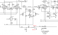
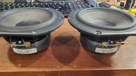
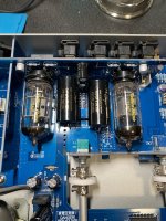
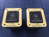
This seems to be an early version, with 600 Ω outputs only. PC board date is 1980.....
20230114_084145[1].jpg
20230114_093311[1].jpg
The opamps employed are of the same era... glorified 741's and 300 series.....
MC1741 (x3)
LF13741 (x1)
LM310 (x1)
LM318 (x4)
....all directly soldered to the board, among a mixture of carbon and film resistors, etc.
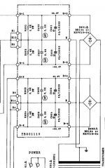
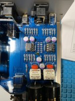
Without a schematic or a Cal guide, I don't know how to adjust all the trimmers for lowest distortion.
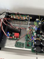
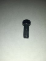
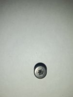
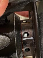
I did pull the 741 types, and added sockets. Also, under the board I soldered some 100nf cer. caps to each power pin, to ground.
These opamps were lacking these, whereas the LM310's already have them.
20230114_195325[1].jpg
20230114_195345[1].jpg
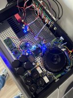
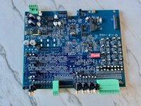
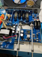
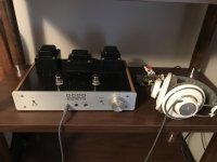
Below, is the entire board, during the cap replacement, but before the 4 opamp swaps (on the left)
20230114_083808[1].jpg

You might be able to see that i swapped to newer opamps, LF13741 AD845, MC1741 OP27. These were chosen from my spare chip collection.
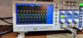
There was an improvement, where the 2&3rd harmonics were now several dB lower.
The only way I can test distortion is using the FFT measurement on my R&S scope.
DC is removed via trimmers on the rear panel...obvious and easy.

I did not want to swap any of the 300-series opamps until I can find a proper manual and schematic. (I've looked everywhere).
That's where I stand. Anything you want to add is appreciated.
=R=
  • Like
Reactions: Hipocrates

NAD 319 rebuild project

Hi

I have an old nad 319 amplifier, which unfortunately is completely screwed up. The protect circuit would not turn off. In the beginning, it was only the relay that messed up the signal, but when I got that fixed, the voltage wouldn't drop on the TA7317 (protection circuit). After days of soldering measuring and burning components, I have come to the conclusion that I need a new psu-pcb. The only thing keeping this pcb together is the soldering mask. There is a +/-67V and a +/-60 V on the board. The 60V, which supplies the emitter-followers appears to be very stable, but the 67V running the protect circuit and signal amplification is very unreliable. This is the bottom view of the pcb:

An externally hosted image should be here but it was not working when we last tested it.


(I have added some resistors to discharge the capacitors, while trying to fix it).

The question is: Do you think I should try to make an exact copy of the old layout or should I just make sure the connectors are placed correctly?
Before I start my pcb program - has anyone else done this before? The pcb is the same as the one in nad 317.

Regards
Christian

PCC85 vs ECC85

Hello!
I was looking at the PCC85 curves, simulated a simple common cathode triode stage using an ECC85 model, and noticed that the anode voltage for the given bias was way off chart. First I blamed the model, but looking at the ECC85 datasheet I saw the curves are different from the PCC85, and both models I used matched the ECC85 curves. Both datasheets seem the original Phillips. Is that a fact that the tubes are that different, other than the obvious heater requirements?
Below the difference in anode voltage for a -3V bias, Ia 7.5mA, 262V vs 215V. I keep looking for the stupid mistake I may be doing but can't find it.
Regards,
Jose
ecc85_vs_pcc85.png

My first CFP power amp

Hi all!
It has ben many years since my last post here, I guess some 20 years, I am now retired an have some more time to my Hobby.

I am working on this CFP, which causes me som troubles.

I would be wery thankful if any of you could give me a hint to solve my little problem.

I have attached files to give you an idea of my project.

Micro-Cap schematic:
2022-12-01 12_54_54-Greenshot.jpg


Kicad schematic:
2022-12-01 14_27_32-Greenshot.jpg


KiCad pcb
2022-12-01 14_15_55-Greenshot.jpg


KiCad 3D
2022-12-01 14_17_39-Greenshot.jpg


Pcb under test
20221201_124622.jpg


Test setup:
20221201_145855.jpg


Here is the problem:
1. When I power up the amp without speaker connected all is fine and dc off set at the output terminals is 70mV. After powering up I can connect the speaker and hear some music.
2. Powering up with the speaker connetcted causes the amp to draw a lot of current, and I have 6V on the terminals.
3. Powering up with a cap in series with the speaker, all is fine and I have music in the speaker.
4. Powering up with an 120 ohm resistor in series with the speaker also does the trick, with les music volume of cause.

I really would appreciate som help, please!

Henrik

Klipsch Lascala Klipschorn Belle Klipsch Cornwall replacement woofer just came out

  • Cabinets: Klipschorn, Belle Klipsch, Cornwall, Lascala
  • Perfect visual match for restored Klipsch cabinets
  • Triple-roll surround and paper cone provide a perfect tonal match
  • Replacement for K-43-E, K-33-B, K-33-J, K-33-K and more.
https://www.parts-express.com/GRS-K...oofer-for-Klipsch-Speakers-292-830?quantity=1

"Shadow of The Colossus" build thread

BBY74cI.png


Have been liking the sound coming out of these 15" bass modules (https://www.diyaudio.com/forums/multi-way/277565-legis-horny-tales-20.html#post6233392) also when used as a 2-way woofers and one idea lead to another.😀

I already have the "closely TH-4001 clone" horns from Usher D3 and the 15" top and bottom bass modules so I will only have to build separate middle modules that sit between them.

The speaker will likely be 2,5-way and passive single amp system, driven with a flea watt tube amp😉.

The ready speaker will be 230cm tall and 115cm wide and 40cm deep. Lot's of Sd and even Vd even though they are sensitive pro drivers. They only consume 0,92m2 of floor space per pair and they can be pushed completely against the wall as the terminals are at the front baffle.

The 12" drivers are already ordered and I decided to get Fane FC-123F02 (got the last stock, it's discontinued model) which are pretty much the closest 12" equivalent for the 15" FC-153F01 woofers which the others are.

They seem to have the same kind of motor which has copper faraday sleeve since the impedance is also very low 25ohm at 20khz. The motor has superbly low H3.

We'll see how they sound raw/wo xo and measure when they arrive from the foggy island.😉 Will post some measurements...:redhot:

gJILzEx.jpg


Here are couple of sims.

FC-123F02 in 80l box (qtc 0,495) and FC-153F01 in 110l box (qtc 0,55). The phase should be quite agreeable inside +/- 10deg between them.

yZd1WWH.png


Here's a sim imported from the Vituixcad's diffraction tool. the 2x2 12" matrix is full range 0deg and the 15" 0,5-way woofers have 15mH lowpass coil.

Just to get some idea how the matrix will lobe off-axis. Seems to behave quite good "many tens" of degrees, and the power response is quite even at least in sim. I presume they will propably work best in at least slightly treated rooms where the frontal/listening window response dominates the power response (in how you percieve the balance and what the listening spot response is), so I don't have unrealistic hopes for superbly well behaved power response. Low acoustic xo point around 700-800Hz will help.

5jVXHKe.png


I already have a 2-way "Colossus lv1" system playing here🙂 Works quite good even with a proto xo with only 1mh coil as a low pass for the 8ohm wired mids so almost everything comes through. The phase is something like 100deg wrong/makes a step at the xo point, so adding another pole to mids (like in Usher D2/D3 it is) should fix that. Big closed Sd is a funny thing in nearfield.😛

Couple of videos:
1: Lv.1 Colossus - Yao Si Ting - YouTube
2: Lv.1 Colossus - Unforgiven - YouTube

39X4DCE.jpg


Here's the listening spot response of the Usher D3/TH-4001 horn (with TD-4001) with no toe in like in the picture, with the original Usher D2 xo (without the small low pass coil that is there to tame TD-4001's 20kHz peak).

3KdADLD.jpg
  • Like
Reactions: behappybevegan

are there any plans out there for FAST / WAW / Acoustic Suspension / Sealed Bookshelf Speakers?

I want to make a couple AC bookshelf speakers with a single full range driver, I see there is quite a bit of info for 2 way AC builds, but I'm really keen on just a single full range driver.

in regards to FAST / WAW, I have an idea bouncing around in my head for adding a passive radiator to them or a couple smaller SA subwoofers for a 2.2 setup at my office desk.

I don't have any real ideas on what I would use for an amplifier...though there are a couple of affordable DiY kits by Decaware that have caught my eye. I also don't have any driver selected, but I expect if there is a suitable plan out there it will direct me with what I should use.

if the music these will play will help with suggestions, my tastes are quite eclectic but for the last couple of years I've had a steep leaning towards orchestral and instrumental with a preference for the strings.

I've been reluctant to play with the speaker calculators as I have dyscalculia / dyslexia and a very bad memory due to a TBI (which is why you'll find me to be quite eccentric or oddball) I survived 24 years ago.

what say have you? also, many thanks in advance for the patience and long-suffering you may find the need to exercise due to my inferred peculiarities. 😉

Noam's ridiculous weekend project

I really wanted to see if I can help my cartridge stylus do the impossible, that is, tracking a groove.
So I've built my own LP weight outer ring.
There are such rings to buy on the internet... but they are crazy expansive! 500Euro or more...
I have searched for some alternatives until I came up with the idea of using Epoxy and coind for extra weight. In the end I'm glad I did! This construction is maybe crazy but truly works.

The benefits of puting such weight on a record is threefold:
-Damping the tiny tiny vibration created by the stylus.
-flatting out wraped records
-adding outer mass- eventually a stable speed.

The downside:
-Could be too much for the motor system?
-need to be carefull with cartridge placement.

Cost=15€ (epoxy is not cheap)
But the result are awsome 😀

Resaults:
Better then I hoped for! a defintive step up in resolution, better details and gain in clarity. It just feels more in control and less background noise.
It wouldn't make me stop looking for a better phonostage or cartridge but it is a bigger upgrade then I hoped for.
After two days of playing with it I had a visitor for a listen... he concluded that I'm not halucinating and that there is indeed a big step up in resulotion... however he also added that ring tooked some liveliness from the recording. I have to admit, it does sound quiter with the ring on.

So, maybe great addition for your turntable or an absolute waste of time, depending on your preferances.

Maybe it will inspire you to do the same 😉
20230108_121005.jpg
20230108_134137.jpg
20230108_151623.jpg
Screenshot_20230117-100554_Gallery.jpg
Screenshot_20230117-100533_Gallery.jpg
Screenshot_20230117-100419_Gallery.jpg

Attachments

  • Screenshot_20230117-100533_Gallery.jpg
    Screenshot_20230117-100533_Gallery.jpg
    138.2 KB · Views: 169
  • Screenshot_20230117-100557_Gallery.jpg
    Screenshot_20230117-100557_Gallery.jpg
    164.8 KB · Views: 154
  • Screenshot_20230117-100542_Gallery.jpg
    Screenshot_20230117-100542_Gallery.jpg
    88.3 KB · Views: 159

Is there some tool to compare Basta! sim of box + baffle/step + room gain response?

Just playing with Basta! and like how it's one of the only tools I'm aware of that simulates box + baffle + room gain responses all together.

Is there a way to compare its response prediction with some other tools, just to sanity check?

Basically, Basta is indicating that room gain helps certain drivers reach acceptable F3s and F6s that otherwise wouldn't look so good.

For sale: Pair of TAMURA F-7002 3.5k 300B output transformers

Pair of TAMURA F-7002 permalloy core 3.5k 300B output transformers made by Tamura Seisakusho Ltd.

Primary: 3.5k ohm
Secondary: 4, 8, 16 ohm
Max Allowable DC Current: 100mA

Tamura Specification.png


Price: US$1600 plus shipping of your choice of 8.5kg plus packaging to wherever in the world you are. Payment by PayPal.

Attachments

  • IMG_3526.JPEG
    IMG_3526.JPEG
    508.1 KB · Views: 261
  • IMG_3537.JPEG
    IMG_3537.JPEG
    225.3 KB · Views: 262

Celestion Ditton 66 acoustic damping foam advice

For Celestion Ditton 66’s might there be some consensus on the best material to use for foam acoustic damping?

When I had the crossovers serviced a few years ago I think that the boxes might have have been missing some foam which I’d like to make good.

Should I buy some 014-0431: Jantzen Bitumen Standard Panel, 4mm thick - self-adhesive (quite expensive, and not what was in the original cabinets) or would 014-0420: Jantzen Wool Fabric probably do the job? Or something else? Naturally, I’ll try to keep the filling as evenly matched as possible for the two speaker boxes.

I’m hopeful that attending to the damping will produce a cleaner and perhaps more dynamic/forward sound?

Have scanned through the many ’66 threads but would appreciate some advice even if it's only to direct me to the best section of a pre-existing post.

Many thanks.

Vifa / Peerless NE123 and NE149 coil offset / production tolerances or are these midrange versions?

I snagged four NE123W-08 and two NE149W-08 from a local dealer who was closing out NOS.

The first pair had a label attached reading "Tymphany NE123W-08". A very long extended pole piece and copper ring nearly as long are visible through the venting holes of the VC former. The winding extends about 2 mm beyond the top plate. In typical Peerless fashion, the second layer is missing 1-2 turns at the top (this improves Bxl symmetry for cylindrical pole pieces). 2 mm top overhang for a stated x-lin of 3.1 mm seem on the low side but are probably ok given tolerances and intentional offset.

The second pair came without those labels attached. There are Vifa/Tymphany badges on the frame and a sticker reading RM Vifa 4". Coil overhang is only 1.5 mm in one and 1.0 mm in the other driver.

The pair of NE149 drivers has the same badges and stickers reading RM Vifa 5.25". Coil overhang is about 1.6 mm in the first and a hair above 1 mm in the other which is really low for a stated x-lin of 5.0 mm.

What kind of overhangs and variation have you observed in this series of drivers? Is there a change RM stands for midrange and these are actually drivers with a shorter coil?

This thread here has pictures of the NE149W, and according to the impedance plot, it must be a -08. In the third picture, I can count about 10 turns, and the picture is taken from slightly below the top plate, so it might even be 11 turns. I count three turns in the shorter of the two drivers (pic below).

https://techtalk.parts-express.com/forum/tech-talk-forum/57431-vifa-ne149w

Attachments

  • RM Vifa 5_25.jpg
    RM Vifa 5_25.jpg
    93.7 KB · Views: 199

refitting drivers flush with front of speaker box

I use a pair of Monitor Audio Monitor 3 rosewood floorstanding towers, which seem to be quite good, but possibly look better than they sound. But lately, I've been getting the urge to rebate the front of the boxes to fit the drivers flush, to give a more posh look. I have no idea whether the sound would improve or get worse, and have zero way of calculating or guessing, so I was just wondering if anyone could give a clue as to what may happen - assuming I don't screw it up of course !!

Pam8304 as boosting amp for Adau DSP

Hellas,

i was wonderung if someone can direct me towards a solution for a boosting amp, to put between a tinysine dsp board (TSA1701, with ADAU1701) and the amplifier i choosed to use, which requieres roughly 2 volts input to be driven in full.
So far i came up with this "brilliant" idea PAM8304 dual amplifier board, which would be marvelous, if it could be a workaround, because it houses two of these little PAM8304 amps. Hence the question how good is this realy in terms of audio quality or would i just out in the next bug of noice between my amp and the dsp? (of course a would have to adjust the output by regulating it through the dsp)
The problem of the tinysine and also the minidsp 2x4 is there low output voltage of around 1V, which is great for lowlevel amps but can't realy drive other amps above that. And a real workaround, for a decent price i could not realy find or got someone a good idea of how to achieve an higher output?

Would be glad for some tips!

Swany

New to me Gary Dodd headphone amp

So today i acquired a new to me headphone amp designed and built by the late Gary Dodd of Dodd Audio out of Texas. Not new, and based on what few posts i can find, there weren’t many made. And I’m not sure anyone has any documentation which why I’m here - I’m looking for first a schematic, and a owners manual would be nice too.

I opened it briefly before i purchased it. Not too complicated Gary’s reputation included using very good parts and his stuff got lots of high praise (from more than 1 poster!). Its a single ended design with output custom Dodd transformers designed qnd built for his gear. He also built and sold a line of boutique tube amps and a battery powered tube pre! in addition to these headphone amps.

Listening now and am very happy with my purchase.. lots of detail, mids are tube sweet and hearing things I’ve not before. (But this is my first dip into better headphone space, so maybe this is what i should expect.

Sadly it seems Gary has since passed and it seems like it was before he got a chance to grow what sounds like a business around some pretty nice builds. Too bad for us…

So for now, if someone has any documentation or knowledge of how to get it, that would be a big help! Thanks

Pic attached. And if anyone wants more, let me know.

Listen on…. and keep your smile.

Attachments

  • 5EF44B56-DDCA-47C9-829A-43B3B71230F3.jpeg
    5EF44B56-DDCA-47C9-829A-43B3B71230F3.jpeg
    291.5 KB · Views: 252

4PR65A tube triode single ended amplifier experiences/opinions

Hi does anyone has experience with the 4PR65A tube as a single ended amplifier?
Its supposed to generate 15w in triode. There's a amplifier on sale that has rectified with ey500 and ecc40 is input tube.
I'm not sure what to expect. Someone has built this and im going to listen to it tomorrow 🙂. Its for sale for €600.
Im not experienced in diy, so Love to hear your opinions and experiences and tips on what to check when auditioning. 🙏

Attaching controls to 10mm front panels

It would appear that some controls for pre-amps are not meant for use in thick front panels like those supplied with some Modushop chassis. For example, the Alps volume controls only have a shaft length of 20mm, including the threaded part, which would not allow sufficient shaft to mount anything but a very thin knob on the outer side.
Is there a smarter alternative than having to resort to CNC drilling and rebating that one can do at home?
Thanks
Projects by fanatics, for fanatics
Get answers and advice for everyone wanting to learn the art of audio.
Join the Community
507,715
Members
7,885,633
Messages

Filter

Forum Statistics

Threads
406,112
Messages
7,885,633
Members
507,715
Latest member
espacoipiranga