Hi all,
While thinking about ways to speed up the settling of a single-supply single-op-amp RIAA amplifier, see
https://www.diyaudio.com/community/...upply-phono-preamp-design.413571/post-7702435 , I found a way to include a second- or third-order Butterworth high-pass filter. As it may be useful outside the context of single-supply circuits, I give it a separate thread.
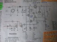
When you just look at the topology and ignore the component values, this is a rather conventional RIAA amplifier (you could make it even more conventional by connecting R
7 in parallel with C
5, that doesn't matter much for the principle):
Normally, C
8 is used to cause roll-off in the subsonic region and the network R
7...R
9, C
5, C
6 realizes the RIAA poles and zero. In this case, however, I use C
8 to realize the lowest RIAA pole at -1/(3.18 ms) and R
7 to get subsonic roll-off.
Note that
C8/
C5 = 1000, meaning that without the subsonic roll-off, the DC gain would be 1001, a very ordinary value for a moving-magnet amplifier (1 kHz gain roughly 40 dB).
With everything ideal, at the value of the Laplace variable
s where the impedance of C
8 cancels the impedance of R
12, the feedback disappears and the gain goes to infinity. This means that there is a pole at exactly -1/(
R12C8), so if this has to be the first RIAA pole, one needs
R12C8 = 3.18 ms. It's actually 3.196 ms in the schematic, pretty close.
The disadvantage of using C
8 for the first RIAA pole is that C
8, which has a relatively large value, needs to be accurate to get an accurate first RIAA pole. (C
8 has practically no effect on the gain at frequencies much greater than 50 Hz, so its tolerance affects deep bass, but not channel balance.) The advantage is that you can include better subsonic filtering in the loop by adding two more resistors and a capacitor.
As an intermediate step, suppose you could add an ideal inductor with a huge value between the output and the negative input of the op-amp, chosen such that it resonates with C
5 at the desired subsonic roll-off frequency, and that you chose
R7 such that it damps the LC circuit to a quality factor of 1/2 √2. The subsonic response would then be very close to second-order Butterworth. That's because the gain of the RIAA correction amplifier is one plus the ratio of the feedback impedance to the impedance from the negative op-amp input to ground, and that "one" is quite negligible at low frequencies. Mind you, R
8 and R
9 contribute to the damping of the LC circuit, but not by much. You could also choose a quality factor of 1 and design the AC coupling at the input for the same cut-off frequency. The combined response is then third-order Butterworth.
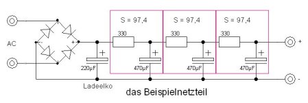
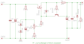
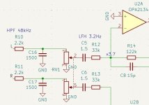
Such an ideal inductor is totally impractical, but it can be approximated with a T network consisting of two resistors with values much smaller than
R7 and a capacitor to ground at the point where they are connected, see this figure:
The transfer from the voltage going into R
11 to the current coming out of R
10 rolls off at a first-order rate from some very low frequency onwards, like would be the case with an inductor.
I haven't found any simple exact equations for any of the values except
R12C8 = 3.18 ms. In fact, I've been very lazy and just calculated approximate values for the other components, and then used a pole-zero extraction program to fine-tune the values.
Regarding those approximate calculations:
R12C8 = 3.18 ms to get the first RIAA pole at the right spot.
The DC gain would be 1 +
C8/
C5 without subsonic roll-off, so
C8/
C5 = 1000 gives you a midband gain of roughly 40 dB.
At
s = -1/((
R8 +
R9)(
C5 +
C6)), the impedance of the network R
8, R
9, C
5, C
6 goes to zero and the gain of the circuit becomes 1. As a gain of 1 is pretty close to 0, this must be close to the location of the RIAA zero. That is,
(
R8 +
R9)(
C5 +
C6) ≈ 318 μs
At
s = -1/((
R8 +
R9)
C6), the impedance of the parallel connection of C
6 and R
8 & R
9 goes to infinity. The impedance of the whole feedback network remains finite due to the other branches R
7 and R
11, C
7, R
10, but it does get pretty large. That means the second RIAA pole must be close, so we get the extra criterion
(
R8 +
R9)
C6 ≈ 75 μs
The (theoretical) inductance
L is chosen to resonate with C
5 at the required subsonic roll-off frequency and R
7 is chosen to get the desired quality factor.
R10 and
R11 get convenient values much smaller than
R7 with
R10 also much greater than
R12. We then have
C7 =
L/(
R10R11)
Best regards,
Marcel
Edits:
Input RC coupling
The RCR T-network that approximates an inductor actually approximates an inductor with inductance
L =
R10 R11 C7 and a series resistance of
R10 +
R11. At low frequencies, it stops behaving inductively, it just turns into the series connection of the two resistors.
As a result, one of the zeros of the high-pass filter that are supposed to lie at
s = 0 actually lies somewhere around
s = -(
R10 +
R11)/(
R10 R11 C7). For the second-order cases, I have used the first-order high-pass at the input to cover this zero by making the input
RC time constant approximately equal to
R10 R11 C7/(
R10 +
R11), or actually to a more accurate value for the displaced zero found by the LINDA pole-zero extraction program.
For the third-order case, I have used the input RC coupling to make the real pole of the third-order Butterworth response, so I couldn't use it to cover the displaced zero. I used the output RC circuit in that case, or simply did not cover the zero. The effect of the zero not being in the origin is typically only seen below 1.something Hz anyway.
There is another zero not exactly in the origin, this is related to the + 1 term in the gain expression of a non-inverting op-amp amplifier. It is so close to 0 that I decided not to bother correcting for it.
Regarding the single-supply versions, the filter R
1, C
1 is meant to provide some power supply ripple and noise rejection. (Even though the single supply has to be regulated, some extra rejection is very useful at the input of an amplifier that amplifies hum frequencies hundreds of times.) R
2 and C
2 in series with the cartridge impedance also help to suppress supply ripple. The second-order versions have greater values of C
2 than the third-order versions and therefore have better ripple rejection at the lower audio frequencies (such as 100 Hz or 120 Hz).
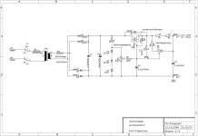
16 Hz split-supply versions
This is a version for split supply and 16 Hz cut-off frequency, see post #58,
https://www.diyaudio.com/community/...rworth-high-pass-included.413649/post-7927611
For the second-order version (values in parenthesis), the input coupling capacitor C
2 can be replaced with a short circuit if you don't mind when the roll-off reduces to first order below 1.3 Hz.
This is a variant with 46 dB rather than 40 dB midband gain:
Thanks to having R
6 split into R
6 and R
0, the time constant of the input RC coupling network can be set more accurately without needing awkward values for C
2. This was implicitly suggested by hbtaudio on another thread. Because of the high midband gain, the op-amp needs to have a fairly high gain-bandwidth product to get accurate RIAA correction (16 MHz gain-bandwidth product will give about -2 % error of the location of the second RIAA pole).
Finite gain-bandwidth product
See post #100,
https://www.diyaudio.com/community/...rworth-high-pass-included.413649/post-7964481 , for some rough calculations on the effect of finite gain-bandwidth product of the op-amp.
From post #101 onward, Nick Sukhov points out that an amplifier with a high open-loop output impedance would result in a loop gain that depends much less on the RIAA correction circuit impedance. That's something to keep in mind when designing a discrete amplifier, you don't have the ability to choose a high open-loop output impedance when using op-amps.
Applying the subsonic filter to a discrete preamplifier based on the Hoeffelman and Meys configuration
The discussion with Nick and Chris about open-loop output impedances made me realize that the subsonic filter of this thread could be combined with a low-noise ("electrically cold") input termination resistance realized with a special feedback configuration that Dual already used in the late 1960's (CV40 phono section, see
https://www.diyaudio.com/community/...o-input-load-modification.424717/post-7947176 ) and that was advocated by Hoeffelman and Meys in a 1978 AES article (Jean M. Hoeffelman and René P. Meys, "Improvements of the noise characteristics of amplifiers for magnetic transducers",
Journal of the Audio Engineering Society, vol. 26, no. 12, December 1978, pages 935...939, see also Ernst H. Nordholt, "Comments on "Improvement of the noise characteristics of amplifiers for magnetic transducers"",
Journal of the Audio Engineering Society, vol. 27, no. 9, September 1979, pages 680...681). The very first electrically cold resistance was made by William Spencer Percival and W. L. Horwood in 1939 as far as I know, but they used a different configuration and did not apply it to phono preamplifiers. See W. S. Percival, "An electrically "cold" resistance",
The wireless engineer, vol. 16, May 1939, pages 237...240.
The schematics below show the resulting configurations. They are identical, but the left schematic is for people familiar with nullators and norators, the right schematic for people who feel more comfortable with high-gain twoports and op-amps. At frequencies well above 50 Hz, the input impedance approaches (
R13 +
R14)/(1 +
R13/
R12 +
R13/
R10). You can make this equal to 47 kΩ while using an
R14 that is much greater than 47 kΩ, thereby reducing the thermal noise current √(4
kT∆
f/
R) that gets injected into the input.
You can't do this with op-amps (not without floating supplies anyway) because op-amps lack the negative output that conducts a (signal) current equal but opposite to the current through the positive output. That is, you can make electrically "cold" resistances with op-amps, but not as shown here.
Document about dimensioning the circuit
The attached zip file contains a pdf document that explains step-by-step how the component values were found (section 2) and that presents a more accurate method than I have used (one that doesn't need fine-tuning with a pole-zero extraction program, section 3). It also contains a spreadsheet for the more accurate way to calculate the component values.
Deriving the expressions was a nice exercise, but I'm not at all convinced that my more accurate calculation is of any practical use. It can very easily lead to negative or complex resistances.


