A Note On The Binary to Thermometer Code Decoder

The advantage of segmenting a DAC is well known - not only to increase the accuracy but also to greatly improve the glitch behavior. The idea here is to build a segmented binary to thermometer code decoder using diode ROM's. To motivate the problem, consider a DAC with 3-bits segmented. (Now, only the DAC is segmented. Not the thermometer decoder yet). For this case we need a n-3 bit binary coded DAC and 2^3 - 1 = 7 additional segment resistors. These 7 resistors must be fed with a unary code, which can be generated using the decoder below. 3 MSB bits go into a active-low 3-to-8 decoder (not shown) on the left hand side. Its outputs are fed into the diode ROM. Three specific input-output examples are given in respective colors.

3 bit.png


This ROM uses 28 diodes. Note that everything here (the number of diodes, current sank by the active low pin...) increases wildly with the number of the bits. For example:

2 bits (3 outputs) decoder needs 6 diodes
3 bits (7 outputs) decoder needs 28 diodes
4 bits (15 outputs) decoder needs 120 diodes
5 bits (31 outputs) decoder needs 496 diodes
6 bits (63 outputs) decoder needs 2016 diodes

and so many * currents! So, the WHOLE MESS grows way faster than the number of outputs needed (something like 2^n times faster). AFAIK inside chips this problem is handled using row-column decoders with some separate logic to control every single matrix element... Boy, this is not for DIY, not for me. So, I wanted to see what I can cook with n = 2 units below (with 4 outputs) and regular ROM with 3 outputs, similar to the one given above. The reason for adding the unit with 4 outputs will become clear soon.

2 bit.png

What kind of device do I need?

Hello,
can somebody tell me what kind of device we need?
or how to set a fp10000 parallel (not bridged)

I need a device that can split the signal after the speaker management into multiple amp channels. something like a y-kable but without loss.

normally I would turn the amp into parallel mode, but I don't know how this is possible with ours (prokustk fp10000q)
and the manual does not show such an option.

currently are we using 4 channels of our DSP just for the bass. but it's mono and all have the same settings. and we could use the free channels

we are amateur but constantly tinkering on our soundsystem

we are currently running a system of 4-16 kickbins, 2 syntripps as tops,

the tops are powered by
crown XS 500 and 900

for the kickbass we are using
up to 16 dynacord fe100lo

sometimes we add 2 bins of the 18sound horn sub
for deeper frequencys

thanks for the help

For Sale Scanspeak 28W/4878T00 sub drivers

Dear diyAudio readers,

I am selling 2 pieces of Scan-speak Revelator 28W/4878T00 sub drivers. They have been used once and only for testing. Overall they are like brand new, minor scratches inside mounting holes because of the screws.

Price is 500eur/piece if bought separately (retail is around 750eur/piece). If you would like to buy both of them together, the price will be 450eur/piece.

I can ship worldwide, however would prefer Europe.

Attachments

  • sub.jpg
    sub.jpg
    257.6 KB · Views: 136

KiCad files: 'The Vulture' a super simple Jfet buffered XO with PSU

So i built OTL direct coupled electrostatics with some decent woofers and i needed a proper XO. I love Jfets. I got them everywhere. I even got them in my purse. Dunno for what, but i'm prepared for the unknown ;-)

However, bored of DSPs and bored of turning XO knobs the whole day instead of listening, i started to design a Jfet buffered PLLXO. Thing is i like my stuff minimal. Also i have a specal affair with single ended 2SK170s. I know i'm not the first to create a Jfet buffered XO and i know Nelson has the genius 6-24 J113 ready for sale. Not saying that's bad, i love it. But i like to etch stuff myself. Single ended, single layered cool old skool. No China. Strictly.
I didn't use CCS in this design. I am using 2SK170 with bias resistors all the time and with a good PSU i have no issues. Noise from my OTL amps is louder than the Jfets anyways. And honestly i never had audible noise from the Jfets even with my headphones. Also i want to use 2SK170BL. These are rare and expensive.

Please bear with me i'm more enthusiast than a pro. Work is still in progress. Also i'm still on a learnig curve in KiCad. I tried it all on a perf board and it worked.
I'm sharing the KiCad files with you for giving back SOMETHING to the community after a decade of silent reading. Also i hope smarter people than me will pick this up and make it something even better. There is potential for that and as said the PCBs are not perfect yet, tho working. There has been the Adason PLLXO, but i found the design still too complicated for no reason (complimentary Jfet pairs and dual rails and still decoupling caps).

So. This is the 'Vulture' Jfet buffered PLLXO. I called it so because the schematic looks like an abstract vulture ( you need a bit of phantasy for that) 🙂. You can build it in dual mono if you wish. Everything is prepared for that. You will need 6x 2SK170BL matched @10mA. Actually everything between 9 to 11mA should work fine. There is also a PSU using the LM7812. Can be substituted with the 340-12 which is better on paper. There are quite a bunch of caps, probably makes Nelson smile when he sees that. The transfo is an encapsulated Talema 70063K toroid with 2*115V / 2*15V. It's wired for 230V but can easily be changed for the US.

The PCBs are 160x100mm Euro format. There are Hammond enclosures for this form factor. I did not include fuses in the schematic/PCBs because i like to use fuse holders which allow access from the outside of the case. So don't forget your fuses.

The PLLXO itself is first order. You can easily make it second order by adding another PLLXO stage between the buffers / after the first stage. It's really easy. Just use the same parts. 6db+6db makes 12db/Oct.

I think you can't make this any simpler. It's really just a few parts that make a superb active crossover. The right thing for minimalists. Actually you can make this a complete preamp with nearly unity gain by just adding another stage of Jfets and a 50k stereo pot. Maybe add a source selector and you're good as long your source is loud enough.

Did i forget anything? Ah yeah...How to calculate the values for the XO and where to place them. You need to place four devices:

R_HP = Resistor High Pass
C_HP = Cap High Pass
R_LP = Resistor Low Pass
C_LP = Cap Low Pass

Here is a website that shows how PLLXO (passive line level crossover) work and how to calculate the values.
PLLXO
Jfets typically have very high input impedance. It depends a bit on the IDSS of the Jfets you are using. I recommend to start with C=0.1uf and R=10k and see where it takes you. I'm getting around 200Hz with that config.
I used quite big footprints for the PLLXO parts, so that people with love for PIO caps etc have bit of playground.

Pardon me in advance for delayed replies. I'm self employed... Also keep in mind, there can still be issues with the original schematics. I still didnt etch it but only build it on perf board.

Have Fun!

Attachments

  • The_Vulture_Jfet_XO.zip
    The_Vulture_Jfet_XO.zip
    2.4 MB · Views: 149
  • jfet buffered crossover wo psu.jpg
    jfet buffered crossover wo psu.jpg
    60.4 KB · Views: 200
  • jfet buffered xover psu.jpg
    jfet buffered xover psu.jpg
    59.6 KB · Views: 197

I hear digital and sometimes low hum from all my sources with FiiO FH9 IEM and using Topping HS02 USB isolator introduced even another kind of noise

I bought a FiiO FH9 IEM. When I use it with FiiO K7 USB mode, I hear digital noise. Some very fast beeps in background, slightly audible but annoying. It's present with all power cord plugging combinations. Digital noise is even more audible when I turn the gain switch to high gain. So I bought another Topping D10s DAC and used it as DAC connected to FiiO K7 on line-in ports, using D10s as DAC, instead of built-in USB DAC of K7. This way noise is much lower on low gain but you can still hear it in a quiet place. Much more audible on high gain switch turned on but I use low gain. But is still there though I enjoy this configuration on desktop because you have to explicitly listen for it to hear it. So it's fine but not sure normal.

For portable use, I bought a FiiO BTR7 portable headphone amp for bluetooth feature. It has lower background white noise than FiiO K7 on wireless/USB cable mode. And I bought a Topping HS02 USB isolator for using another charger on power side to avoid using my phone/laptop battery when I don't move around. But this configuration brings a low frequency audible hum that I experienced first time: USB wall plug charger (Apple included, any kind of them) on power side + my phone/laptop/desktop computer etc. (signal side) -> HS02 isolator -> FiiO BTR7 is very audible annoying low frequency hum. This hum isn't present when I connect BTR7 to computers directly or on bluetooth mode with battery power. Direct connection to computer with even longer and cheapest cables don't introduce this noise. This noise is audible even when there is no ground connection as my chargers are 2 prong: Phone + wall charger -> HS02 -> BTR7 combination isn't connected to ground but there is this same level hum. I tried it with various chargers, same. So I don't use HS02 with wall chargers because it makes it unusable. When I use my laptop as power source + my phone as signal source -> HS02 -> BTR7, this noise isn't present even when I connect my laptop to mains power. So I guess chargers are introducing noise but this isolator isn't fixing an already present noise from power line.

Is this an acceptable thing with IEMs? Or is my K7/BTR7 defect? Do everyone hear this noise and ignore it? No noise on bigger headphones with absolutely any configuration on either amp, isolated or not.

For Sale LM3886T National Semiconductor

I have over thirty of National Semiconductor's LM3886Ts for sale, they have been sitting on the shelf for a long time and are not needed.'
Asking 3.80€/ piece.

PayPal is accepted buyers needs to pay the additional PayPal fees from 4% and only with PayPal confirmed shipping address. Shipping prices are different depends on the country. Preference and priority is given to buyers from the EU, to prevent the damn paperwork for shipping but I can send worldwide but it takes a bit time to organize it.

Only Register Mail using FINLAND Posti or DHL Germany.

Optional shipping with DHL from Germany, the costs is significantly lower than with Finnish Post. The payment request occurs shortly (2-3 days) before shipping.

No Customs declaration is required for EU countries. For goods delivered outside the EU, i need to attach documentation required for Customs clearance. Correct Shipping costs need to check in the local Post office.

LM3886 NS (2).jpg
LM3886 NS (3).jpg
LM3886 NS (1).jpg

Older kicker kx1200.1 Powers on but doesn't get loud with pictures

Like I said I have a kicker KX 1200.1 I just purchased to strap to my other kicker 1200.1. I tried bench testing it before installing it in the car and it does power up with no protection light coming on but it has very low output. On taking the heat sink top cover off the amplifier I found this. Would this cause that problem?

Attachments

  • PXL_20240214_043605997.RAW-01.COVER.jpg
    PXL_20240214_043605997.RAW-01.COVER.jpg
    376.7 KB · Views: 85
  • PXL_20240214_043559616.RAW-01.COVER.jpg
    PXL_20240214_043559616.RAW-01.COVER.jpg
    549.2 KB · Views: 84

LRDDMC Loudspeaker Resistor Drive Distortion Measurement Challenge

Nobody wants to know if you hear distortion.

But

Do you measure distortion?


I thought about what a measurement experiment could look like so that the person measuring can directly experience what they are currently doing and achieving.

Do you have a speaker? Good!

Have you ever measured the frequency response of your speaker? Good!

Can you connect a line directly to a transducer in it (leave out the crossover)? Good!

Find a resistor with 20R! Don't worry about the power performance of this resistor! Just keep explosives, your beautiful toddler, your cat... away! 10 Watts is what i use. That's plenty and certainly a lot more than my speaker can handle.

Complete your usual measurement setup.

Carry out a measurement at a very moderate volume. Only the transducer in the box, directly connected to the amplifier. [1]

Save this measurement to overlay. [1]

Then insert the 20R resistor. In series to the transducer. Carry out a second measurement. Increase the volume to approximately the same sound pressure level. [3]

This is all about distortion. So RTFM until you have two distortion charts.
[4] One connected directly and one with the 20R in series.

If you do not see a difference in D3 ask here for help.


This was done at 0,5 Volts at the transducer:
No need to blast your speaker!

20240107 1 fundamental 0R.png

[1] yellow is the fundamental directly connected (0R)


20240107 2 noise.png

[2] Same setup, just disconnected speaker. Noise...


20240107 3 fundamental 20R green.png

[3]
green is with 20R in series.
yellow is directly connected (from [1])


20240107 4 D3o white 0R D3 red 20R .png

[4]
D3o (white) is directly connected (0R)
D3 (red) is with 20R in series

20240108 Edit 1:
I am extremely disappointed by the fact that no one is taking measurements here on diyAudio. There are only theoretical heroes here who type more or less gross nonsense with their keyboard.

20240108 Edit 2:
User >OllBoll< on diyAudio was the first measuring "it".
https://www.diyaudio.com/community/threads/hypex-ncore.190434/page-384#post-4095122
He was cited on a German forum on
12.09.2023, 16:47
9 years (nine years !) later, because there was nobody on the whole internet measuring "it". Now that
Tenson< joined,
https://www.diyaudio.com/community/...ortion-measurement.402566/page-9#post-7558653
we are 3. Please be the 4th ;-)

20240110 Edit 3:
tmuikku< joined (#40), we are 4. please be the 5th ;-)
  • Like
  • Thank You
Reactions: tktran303 and jayme

Stepping down speaker level to line level with audio transformer to feed into power amplifier - does it cause too low impedance issue?

Many Denon AVRs have speaker level outputs for passive speaker connections (mostly around 90W for Dolby Atmos surround systems) and I think I can step down the speaker level to line level to run RCA/XLR cables to speakers with each having their monoblock amplifiers. But the problem is, these Denon AVRs have 4/8ohm output impedances from their speaker outputs and if I use an audio transformer to step down with 1:10 ratio, speaker level impedance being already being either 4/8 ohm, impedance gets even lower to 1/100 ratio of 0.08/0.04ohm. ChatGPT suggests that feeding too low impedance line level signal to power amplifiers can damage the amplifiers. Is that correct?

As far as I understand if I step down speaker level signal voltage with a 1/10 audio transformer, input being 8ohm, I get 0.08ohm (1/100 ratio) impedance. Would this harm a mono power amplifier if I feed this line level 0.8 ohm signal to it?

Not: My aim was to have more gain than Denon provides with separate amps and since power amps I see on internet have line level inputs, I thought of stepping down the speaker level to line level as a solution but not sure if this is a good idea.

Ah revisit of my curved planar magnetic tweeter ! BINAURAL RECORDING, use headphones

Ah revisit of my curved planar magnetic tweeter (bit to much curve though)

Well i replaced the foil since i dont like Kapton, and i forgot i used Kapton.. see if i can raise the top end a little since thats in this case because of the curve the first to go 🙂 and give it another try. Please keep in mind this is recorded with in ear mics so use a headphones for correct spatial sounds etc.
At least this project is not dead.

I play one tune Anette Askvik - Liberty go here if you want to skip the rambling 🙂 TUNE

Login to view embedded media

ELEKIT TU-8800 SET AMP

Available Now....

TU-8800 $1185 (stock version)
TU-8800 $1,785 (Lundahl Version)

Takman REX50G 2% Carbon Resistor (85 PCS) $65.00
Mundorf Supreme Silver Gold 0.01 X 2 + 0.1 X 2 $150

Gold Lion - Matched Pair KT88 X 2 + 12AT7/B739 X 2 $185
TKD 2CP601S $65
The Lundhal + PCB + HV + Hardware is $645
https://www.diyaudio.com/forums/elekit/353407-inexpensive-tube-set-tu-8800-a.html#post6177418

● Rated output: 12.5W + 12.5W (KT88-HIGH mode / UL connection THD 10%)
● Rated input: 360mV
● Residual noise: 90μV (IHF-A)
● Frequency characteristics: 12Hz to 55kHz (-3dB)
● Input impedance: 50kΩ
● Output impedance: 4 to 6.3Ω, 8 to 16Ω (switched by the switch on the back)
● Input terminal: LINE x 2 (LINE1, LINE2): RCA jack 3.5mm stereo mini jack (uses both LINE2 and cuts LINE2 when plugged in)
● Output terminal: Speaker output terminal: Gold-plated screw terminal (banana plug can be used) Headphone terminal: 6.3mm headphone jack
● Power supply voltage: AC120 / 200V 50 / 60Hz (3P inlet)
● Power consumption: 95W
● Body dimensions: W350 x H204 x D324mm (including protrusions)
● Body weight: approx. 12kg (without power cord)


IT SHOULD BE 7581 (NOT 7591)


OPTION: Lundahl OPT


Adcom 5400, Chinese 1998 manufactured, question on the power supply caps

Just got an Adcom 5400, Chinese manufactured 1998, and I opened it up to make sure none of the fuses was blown, and looked at the power supply caps. I see some dark brown at the edges of the caps and it's been noted in other posts that that was a mastic to hold the caps to the board but all of them are loose to light pressure. Should I assume it's the mastic? The tops of the caps are slightly convex. Should I therefore assume they're bad and leaking? No caps I've seen with suspected leakage ever turned out to be bad when I removed them. If it works ok without hum, should I assume it's just mastic goo?

Online Calculator or Freeware Program for Power Supply Design?

Referencing the attachment, it is a power supply I hijacked off the internet and plugged in my own parts values, using plain guesswork. I have no training in this and don't want to keep spending money buying parts and wasting time on my own hairbrain plans. What I want is about 230-235 volts of clean DC with 100 milliamps of B+ available. Note also that there is an "unknown resistor" I put in. There's got to be a better way than this trial and error tinkering. Certainly there must be an online calculator or freeware program where I can just enter parts values and get a reasonably usable expectation. Thank you.

Attachments

  • power supply 3.jpg
    power supply 3.jpg
    108.3 KB · Views: 156

Amplifier for piezoelectric sensors

This is an amplifier especially designed for piezoelectric sensors.
It is a differential charge amplifier but a two pin piezoelectric sensor can be connected to the (+) and (-) input.

The amplifier includes three gain setting (0 - 10 - 20 dBs) and high pass filters (3 Hz- 16Hz - 160Hz).

I have some PCBs available (without any components), if someone is interested to build one.
The dimensions of the PCB are 84mm × 101mm.
The price is 28 Euros (shipping is included).

Attachments

  • 1-The electronic diagram __Version2.png
    1-The electronic diagram __Version2.png
    180 KB · Views: 607
  • 3-Photo of th PCBA.JPG
    3-Photo of th PCBA.JPG
    756.1 KB · Views: 493

in my situation which FR could you be married?

Hello All

I have made a first project with the mark Audio CHR70.3, it sound good, i like them really. I have listen the Pluvia 7.2HD it’s better for not so much. (i have little regret, i have listen them after) For my deskroom wich is small really near it’s enough.

Now for my new project i want to make a 55 sqm listening room…. 2 CHR70.3/ 7,2HD it’s not enough. I will be between 2,50 to 4 m at the listening point, the room is 5,5 m large. I want a depth in the sound image. the more realistic as possible, not boring really dynamic, nearest the of top of the line.

I listen mainly alternative rock,pop, piano, guitar classic and electric, vocal
I have not the possiblity to listen other Mark Audio driver, near me no one have them, in fact really few people use full range/coaxial as main listening system.
There is specialized shop but they want sell finished system… not drivers…
i know the driver don’t make all…it depend of what there is before,for the momment i have :

2 diy 12 inch sub wich can help theses future beauties
i have amp NAD 356BEE (it could be changed, a lamp or preamp can be studyed)
a DCX 2496 for filtration/correction
a DAC

i have read on this forum that there very few very good FR and that the price is not the best indicator, good news i have not the budget for the cube audio unfortunatly, even a lowther.
For this project I see bigger, stronger, better…and go to best as possible,due to budget i will be maried with it for minimum 10 years. And you with wich drivers could you get married the rest of your life in theses conditions?

Martin Logan Ethos 2024 Active (DIY)

Just finished a small project adding a Hypex NC500MP under each speaker to make them active. Also had the cabinets spray painted in satin gray polyurethane furniture paint. I think it looks more up to date 2024-ish. By the way, the hypex does quite good driving the ESL load. I had a dialogue wiht Hypex (nice people!), and they confirmed that it would not be a problem with the ESL load. This is a point where Hypex differs from Icepower. Icepower would probably have a challenge with the capacitive load. Anyway, now my Ethos are fully active with hypex driving the esl's and icepower for the subs. Works nice 😉

What do you think?

IMG_4233.jpeg
IMG_4234.jpeg
IMG_4235.jpeg

Manual Request

Hi everyone,
I'm a tape deck lover from Hongkong, I recently bought a AIWA XK009. I want to know everything about it, but I couldn't find user manual anywhere but hifiengine. Sevice manual is everywhere but not user manual. And hifiengine do not accept any new members. I am in a dead end.
So someone kindly enough plz help me download the user manual from hifiengine and send it to me? I would be most grateful.
https://www.hifiengine.com/manual_library/aiwa/excelia-xk-009.shtml
My e-mail: xyhtony@hotmail.com
Regards,
Shawn

Discussion: The relationship between the Fosgate PR-250 and the Pioneer AD-360

I recently acquired a Pioneer AD-360 from the late Jim Fosgates estate. At first, I was hopeful that he threw some secret sauce in this one and i'd get to be the only one to enjoy that. Turns out he didn't. In fact, it didn't even work. So my next guess was a friend left it with him for repair because 'My buddy Jim knows amps' is probably how the rationale went.

So I went looking for a schematic. But I was too cheap to buy the service manual. Then I started looking up part numbers. The part numbers led to a thread here

The drawing note on the PR-250 schematic led me down a rabbit hole as not only was I able to use the PR-250 schematic to service my amp, it bears the 'GM160' stamp!


The drawing note:

fosgate-20-copped.png


The board stamp on my AD-360:

D360-GM160.jpg


At this point i'm just MADE of questions. Both of these amplifiers were released around the same time. It's sitting in Jim's house. One board is referenced in another's drawing. They're both 'Made in the USA' which is not common for Pioneer electronics of the era.


What was the relationship between Jim Fosgate and this product?

Did Jim OEM the AD-360 for Pioneer?

Did Pioneer License the design from Fosgate?

Did Pioneer OEM the PR-250 for Jim and Jim added the processing in house?

Was the 'GM160' a build house design both Pioneer and Fosgate custom tailored for their models?

Another interesting note: I have 2 of these amplifiers. Jim's model has no solder mask and the unit bears no serial number or warranty sticker but my other model does!
  • Like
Reactions: BIGDOGBRODAVE

State of the Art for Tracker/Down Converter?

I have started to look at switch mode power supplies that track the audio, a la Bob Carver amps, and later Lab.Gruppen and others.
The use is a home theatre system with tri- and bi-amped speakers, so there's a dozen or so power supplies to build, hence a simple IC based solution is attractive.
What is the current state of the art in circuits, ICs and power semiconductors for this?
The trend in industrial SMPS seems to be towards Zero Volt Switched circuits.
My first impression is that it seems attractive for Audio too, but I see there are some tricks and traps with this technique.
Standard MOSFET or bipolar power semiconductors still look cost effective for < 600 V but perhaps there are new SiC or fancy semiconductors that I should consider.
Any comments appreciated, except that I should just use Class D amps - different discussion!

David

For Sale PCB mount Novar tube sockets

Contracted manufacturer to install 1.0mm pin sockets in Magnoval bases. Tested on 12GT5 Novar tubes.
Money back guarantee if not satisfied with fit. Background link below.
$2.50 each + ship to US, Canada.
Thanks,
Jim

https://www.diyaudio.com/community/threads/real-novar-sockets-inside.397358/#post-7304388

Attachments

  • Big 9 pin dimension.jpeg
    Big 9 pin dimension.jpeg
    13 KB · Views: 186
  • 1.jpg
    1.jpg
    149.6 KB · Views: 167
  • 4.jpg
    4.jpg
    145.7 KB · Views: 174

Proac 2.5 clone cabinet problem

Recently I both drivers (Scan Speak 18w8535-00 + 9500). First I make Troels Gravesen cabinet http://www.troelsgravesen.dk/download/2.5_Clone.pdf. I tried many types of crossovers but withouth result. Sound was muddy, undertone without expanse in middlem, bass was deep but without attack (energy). I think the cause of this was small volumen of the cabinet. After nearly a week of work I quit of this cabinet.
Next solution was Event http://www.audiocomponents.nl/speakers/scanspeak/classic/tekening/event_1.htm. Results was better then previous but sound was bad though. I have opossite sound from previous. Middle was wide but without warming and definition, bass was deep but without definision. I worked on dumping but without visible results. There is last solutin. Close cabinet. I searched internet but without results. I wish to build BR or TL but I'm in the dead end. I have not equipment to mesure T/S parameters and work further.
I'm count on you people 😉
Any hint will be highly woth.
best regards

For Sale Wavecore SW259WA02 10" aluminium cone woofers (2x pairs)

Hi all,

I have for sale my final four of these excellent subwoofers. Superbly engineered and often overlooked drivers from Wavecore. The 4 ohm version was recently reviewed in Voice Coil magazine.

I have 4x available and would like to sell them in pairs please. £400 per pair inc. UK shipping.

Will ship worldwide at cost.

Specs can be found here: http://www.wavecor.com/html/sw259wa01_02.html

Thanks for looking!

Drivers FS

Brand
Model
Qty
Condition
Asking price (sold in pairs only)
ETON​
4-200/A8​
2​
New​
$80​
ETON​
5-200/A8​
2​
New​
$80​
Vifa​
P13WH-00-08​
2​
New​
$100​
Scan-Speak​
P13WH-00-08​
4​
New​
$100​
Scan-Speak​
21W8555-00​
2​
New​
$100​
Wavecor​
TW022WA09​
2​
New​
$60​
Wavecor​
TW030WA14​
2​
New​
$60​
Scan-Speak​
D3004/602200​
2​
New​
$100​

For Sale PCB LYNX Amplifier and LM4870

I have one stereo set of PCBs for the Jan Dupont Lynx amplifier. As a fringe I will throw in one pair of OPA627 (used, desoldered) with the PCBs.
OPs are tested before. Asking price is 10 Euros + postage.
For more info: https://www.diyaudio.com/community/threads/official-lynx-power-amp-builders-thread.118469/

I also have 4 pcs of LM4780. Asking price is 7 € a piece + postage.

Postage as you see fit is added. I accept Paypal and direct banktransfer.

I am EU based (Sweden) for info.

Edit:LM4780s sold.

DH-220C project - power up...smoke!

I've been working on rebuilding my Hafler DH-220 into the DH-220C input circuit - the Bob Cordell designed circuit that's sold by delta9electronics on eBay and I believe is a member here.

Anyway...on power-up, (the rail-to-rail voltage is about 120V or just under +/-60V) and it more or less immediately fried R53, the 22 ohm resistor at the positive rail, along with both R13 and R25 the 180 ohm resistor that power Q1 and Q2.
This was only one the right channel - the left channel seems to have survived.

Questions:
I haven't pulled the transistors, but is it safe to assume they're also toast, or is there a chance they're ok.
What would have caused R13 and R25 to burn.
I presume that R53 blew because of overcurrent at R13 and R25...

Where should I be looking for the root cause?

Bessel vs Critically Damped Enclosure

Does anyone have experience listening to the difference between critically damped (Qtc 0.5) and Bessel (Qtc 0.577) sealed enclosures?

The 'tightness' and 'speed' are noticeably better with lower Qtc enclosures, with systems over Qtc 1.0 not that uncommon, but sound like mud to me.

Will a Qtc 0.577 sound just as tight as Qtc 0.5? If Group Delay is the reason for the muddiness, 0.577 might even sound better.

With a high qts subwoofer, this makes a huge difference in enclosure size. e.g. with the Wavecor SW312WA03, speakerboxlite calculates 236 liters for Critically Damped and 85 liters for Bessel. This is using the 'unbroken in' manufacture numbers, I'd expect qts to drop, and even if VAS goes up, box size comes down. But this is just an example of how big a difference there can be between them for enclosure size.

Obviously extension is also an issue, but I don't want to go into that in this thread.

SET Friendly MTM, Seas ER18RNX and 27TDFC

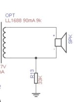
I built this in 2007, with a lot of help here from Jay and Zaph particularly with the crossover. I thank these guys most sincerely!

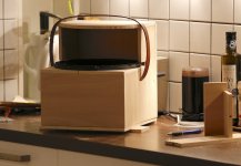
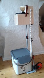
Design was constrained by WAF to about 8.5 inches wide, about 12 inches deep and 1 metre high, also by the amp, my 45 parallel SET giving 3.5 watts (note the decimal point). Don't query the amp unless you've heard a 45 SET, if you have you will understand. Room is 18ft x 14ft.
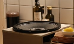
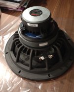
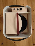
The speaker is about 42 litres, bass reflex to give good sensitivity.

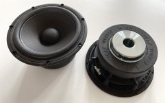
The Q of the bass driver was calculated allowing for amp Zout, giving Qts 0.51 quite high. This made bass alignment a bit of a problem; the ideal volume for a standard alignment became massive. But it was overcome with use of WINisd. With my volume it was not possible to avoid a hump in the bass, but tuning the port to 30Hz got the hump to below 1dB. Group delay was under 10mS at 40Hz (Zaph's criterion), and if I remember, the peak in group delay was moved to quite a low frequency and was not too massive. In fact this is very much Zaph's 'lean and low' tuning; low is obvious, and lean I take to mean removing or minimising the hump at roughly 80 to 100Hz.

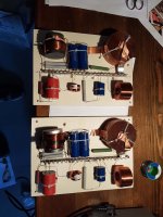
Crossover was very similar to Zaph's one for his MTM with Vifa woofers and 27TDFC, virtually as Jay's suggestion; very simple:
Woofers 1.35mH, 40uF
Tweeter 1.9 ohm series R, 12uF, 0.39mH
The L on the woofers adjusted by ear for BSC, starting value 1.4mH was very good.
Tweeter C was adjusted after SPL measurement to reduce a slight dip in the upper crossover region.

The result?
Superb.
Bass is very good, adequate quantity, reasonable depth, very good quality; nothing boomy; tight, tuneful, fast. I had expected to want to try different port lengths, or straws or damping, but once I heard it I told myself, do not mess with anything! (I've messed electronics up in the past and never got back to the best).

Overall, sound is tuneful, fine tonality, good rhythms, excellent leading edges (says a critical friend who loves leading edges and dynamics); superb vocals. Highly musical. Just seems to do lots of things right in a way that you don't notice them, they disappear.
I like the combination of amp and speakers a whole lot, and I'd put it this way.
In hifi, you might have decent hifi sound.
Go a level higher, and it sounds like better hifi, you notice the hifi things more.
But at a higher level still, I find it sounds less like hifi; I don't notice the hifi things, they go away, leaving a very natural presentation.
These speakers are getting close to doing that.

Liked a lot by hifi addict friends; a Naim addict dynamics freak says they have some dynamics and rhythms (and he's critical, blunt with it, like Craig Revel Horwood, for my own good, and he knows his stuff).
The system does not sound underpowered in any way; for one thing the amp sounds more powerful than my 300B SETs of twice the power. Definitely all the volume I want, without stress.

Anyway, I can recommend this design to anyone who wants to build speakers for a SET amp and is constrained by WAF.

You will soon understand why I'm posting about these speakers many years after the event.

The system is pretty good.
Sources:
Teres turntable (acrylic/lead platter), Moerch DP8 arm, Zyx 4D, far better than previous LP12; good valve phono stage.
Marantz CD65 II (TDA1541A dac chip), lots of caps upgrades, NOS converted, lampizated; superb tonality, great sound.
Valve preamp with 27 triode
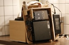
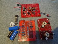
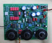
45 parallel single ended amp, separate PSUs for the two stages, massive PSUs, both 2 pi with chokes, film caps, tuned for fast clean transient response.


P1060737.JPG

Which Markaudio drivers for integrated home streamer?

Hi, first time poster so thanks for all the useful info and expert advice on the forum. I'm building a small cabinet for a stand-alone, wifi/bluetooth home streaming music centre. Movable to any room in the house, compact, easy to use with good quality sound. The cabinet will be approx 600mm W x 200mm H x 300mm D (but can be varied to a limited extent) to house a Fosi MC 101 Class D amp, Wiim Mini streamer (aux out to aux in on the amp) and two small full-range drivers. Each driver will be in enclosed boxes at either end with the amp mounted through the baffle in the middle with Wiim behind, both in a separate central (vented) box. The cabinet ends will be kerfed to create a soft, rounded look which may have some acoustic benefits? Front baffle will be an Australian hardwood called Tasmanian blackwood (19mm) with the case in 15mm veneered ply. Rear ports. A mockup image is below.

I'd like to use Mark Audio drivers for this project and would like to ask which ones you would recommend? The driver units can be 5-7cm and ideally would be gold to match the amp and timber. Volume of each speaker cabinet can be 4-6 litres but I could stretch to 9 litres each by extending height and depth if justified in terms of improvement in sound.

In a prototype I used Dayton Audio PS95-8s in 3.7 litre boxes with a DA KAB amp which sounded good but lacked some bass. I understand bass will be limited in such a small system but am hoping MA drivers would offer some improvement at the low end. This is not a boom box, so it's not just about the bass, I would like to have good mid and upper range too. Most important is to get good, clear sound stage from two drivers close together in near field/small room listening setups for all types of music. Also where on the front baffle would you place the drivers - at the far ends next to the curve or further in towards the middle? Do you see any issues in matching MA drivers with the Fosi (one review on the MA site suggests MA drivers and Class D amps are not a good match)? Any issues achieving the required box volume by departing from the online MA speaker plans by increasing depth and decreasing the other dimensions?

MAF Box 1.jpg

Experiences with Infinity products

I'm just curious if others have had the same sad experience, or if the unit I received was in the wrong hands before it ended up with me.
I got an Infinity Modulus subwoofer into the workshop and now I've been working on it for 4-5 weeks on/off. The fuses were blown, the output transistors were shorted (TIP35C/TIP36C), and some of the soldering around the PCB looks like something done in the dark by someone who is only used to industrial welding. My previous experiences with Infinity products are already not good, but can this really be the standard for Infinity products? Just the fact that the unit from factory use TIP35C/TIP36C output transistors (original according to the diagram/parts list) with 100 Volt Vceo for an output amplifier with a supply voltage of +/- 47-48 (= 96 Volts P-P)......??
Am I just unlucky or has anyone else had the same overall bad experience with Infinity?

Using a large, distant TV as a PC monitor?

I spend a lot of time using a 27" monitor - for forums such as this, surfing the internet and streaming music and youtube. I like it much better than using a laptop sized screen, but I'm starting to get tired of sitting at a desk all the time. So I'm thinking of getting a big TV (say 65" or so) to use as a monitor, and mounting it across the room from my armchair, which would be about ten feet or 3m viewing distance.

My keyboard and mouse are already wireless, so it would be simple enough to do. However I'm concerned about the legibility of text and that kind of thing, with it being a TV rather than monitor (and probably not an expensive one, either). Has anyone got or used a setup like this, and if so how did you get along with it?

Thanks,
Kev

EAR834p clone with hum. Would appreciate some help

Hi everyone!

I have built an EAR 834p clone but have a hum problem. I have followed the grounding scheme (see picture) from the Lenco Heaven forum (and also implemented the mods) but is seems like the amp is picking up noise from the inputs. I am a novice and I am starting to feel that I perhaps took on a project to complicated for me. It is a good sounding phono stage and also some money invested so I would be thankful if someone more knowledgeable would like to help me sort this out so that I can keep this.

I have a Rega P6 turntable with a MC cartridge. I bought it second hand but from a reputable HIFI dealer that had checked it. I have not tested it with anything else than my DIY 834p build. I have not owned a TT since the eighties so I know very little about TT grounding.

After a lot of testing I have been able to pin down a few things regarding the hum. I have built an input switch for MM and MC so that I can easily switch to MM in the future if I like. I have hum even if nothing in connected to either input so I know the hum is from the 834p.

If I switch to MM input, and then ground the switch with a wire, hum is pretty much gone. It disappears completely if I put my hand over the MM inputs (from the back of the amp), I do not even need to touch them, just cover them. Same thing if I hold a piece of metal in front of them. So it seem like the inputs and the switch act like an antenna picking up hum from somewhere. I used an app on my phone and measured the hum. I have a loud 50hz peak, and also a 100hz peak thas is not as loud.

When I plug in my TT to the MM input, there is a faint hum, and it no longer makes any difference if I ground the switch with a wire or not. It's a Rega P6 so it has no separate ground cable. Ground in Rega TTs is in the left channel cable. Don't know if that has anything to do with it.

If I switch to MC, with nothing connected to the input, which goes from inputs trough a pair of Lundahl LL1931 SUTs and the to the switch, I still have hum even with the switch grounded. A tiny bit little less when grounded, but not much. I have tried different grounding schemes for the Lundahls and this is the most quiet one, but still way too loud. I only have a MC cartridge, so if I want to listen to vinyl, hum will be present if I do not solve this.

In my build I have made it so that the switch switches both + and -. Is that a bad idea?

I have changed all the unshielded input wires on the picture to shielded, no difference.

Also there is a problem with hum with the Rega P6. I get a really loud hum when I touch the tonearm and sometimes it stays after I let go of it, sometimes not. If I move around the input cables from the Rega this loud hum can also start. When I get this hum, I can cancel it by putting a wire from Right input - (shield) to amp chassis (not the Left channel that supposedly has the TT ground), but if I leave this wire permanently in place I still get hum if I touch the tonearm and to cancel the hum I now need to remove the wire.

All of this is so weird to me.

So, what can I do now as the next step? Do I need to ground my inputs in another manner perhaps? I have seen that some people connect all input - to each other and some don't. I am at loss at this point.

grounding.jpg


ear834p.jpg
back.jpg
  • Like
Reactions: Mildslight

Help for Micro CaP

Hello,
this post can be closed. I did mistakes in shorting some wires in components, error found 🙂


Hello,
is there someone working with Micro Cap? I am beginner with spice and i want to simulate a schematic that is from a book and it works in real very nice.
It is a booster from 12 to 200V with 555 and FET. In Simulation i only get 23V on the output, but it should be over 180V.
Maybe i have an error in there, but i cant find. It would be nice if someone is using Micro Cab and would load the circuit to check.
Thanks,


Andreas

Attachments

First project

Hello 👋 beautiful people.i am 15years and a ugandan. I've been saving for this boom box project and now I have the money. Can some one help me in the plan . I am going to use a hifi stereo amp with 100w per channel to power drivers of 2*65w 4.5inch 4ohm that's sub , 2* 25w 2.5inch 4ohm midrange and 2* 20w 1.5inch 4ohm. And please does the pre amp increase sound clarity because I want a quality sound build . Am using wood as the enclosure and 2 passive jbl 3rd gen radiators thank you
  • Like
Reactions: njswede

Speaker gasket sealing tape

Hello,

I can access places like Element14 (Newark USA, and known as Farnell in UK) or Digikey.

The tweeter as you can see has a fine tape - more to maybe hold the copper dome down. The woofer the foam has long gone, or never was used. The speakers are Celestion SL-6. I fixed the corrosion issue in another thread back in December, with Rust Oleumn 5in1 paint

https://au.element14.com/pro-power/hsht-roll-0-8x25mmx5m/tape-pe-foam-5m-x-25mm/dp/7224825
tweeter and maybe woofer

for the woofer maybe
https://au.element14.com/multicomp-pro/ppc116/sealing-tape-pvc-25m-x-6mm/dp/176068601


P1510498.JPG

P1510150.JPG
P1510150.JPG

HV B+ linear shunt regulator ringing

Hello,

I am testing a design of mine for tube amp B+ supplies, both for input and output stages. Currently setup for the lower current input stage, running at the top of its adjustable range, 170V/75mA, with the shunt mosfet (IRF820) run in linear region (of course) dumping 40mA current. This is a stress test to check for thermal stability and worst-case scenario performance - the shunt will dump a bit less power in normal operation (25-30 mA at 150V). Looks that will make for a decent space heater if anything 😎

Capture d’écran 2024-02-12 195458.png


I am satisfied with line regulation (about 150mV pk-pk), but there is a great deal of ringing (see scope shots). First one is blurred but only there to show the main ripple voltage with the ringing around it as light green, next two pics are close-ups. Sorry with the bad shots, I have only an old scope and I'm not that good working with it. I have measured around 100mV pk-pk ringing at about 50 KHz. Is that to be expected? Note that these preliminary tests were done into a 5K dummy load, without "speed-up" capacitor C1 and output capacitor C3.

IMG_20240212_173217_1594.JPG

50mV/div, 0.50mS/div

IMG_20240212_174158_1598.JPG

20mV/div, 50uS/div

IMG_20240212_174352_1600.JPG

20mV/div, 20uS/div

A few more circuit details: The top device M1 is an IXYS IXCP10M45S current source; The shunt mosfet M3 has a 100 ohm stopper resistor soldered close to the gate (see board pic below). It is a dual mono board with all TO-220 devices on the same heatsink with ceramic insulating pads. In the actual builds the heatsinks will be mechanically connected to the grounded metallic chassis. This test setup doesn't use the heatsink that will be used in actual project but uses the actual adapter bracket (the aluminium flat bar the tabs screw into) and heatsinks are left floating. I will check with grounded heatsinks tomorrow.

IMG_20240212_172510_1592.JPG


I have measured a substantial capacitance of 50-100 nF between the TO-220 tabs (drains) and the heatsink - That can't be good, I fear HF coupling between devices and channels... I have tested only a channel at a time so far. I am not very experienced with parasitics management and would appreciate any advice on how to tame the ringing. I have often seen ferrite beads used in SPMS designs, presumably on the gate lead. Can it help here?

Thanks in advance.
- Joris

Leak Sandwich (original) rebuild and TH parameters

While I'm waiting for my MA drivers to arrive to put together with a KEF B139 I thought I'd get on with a refurbishment project.

I picked up a pair of Leak Sandwich 15 Ohm speakers recently and have finally resolved to rebuild them into larger cabinets - with a separate section for the mid/tweeter and importing a foreign tweeter. Barlow, who designed the drive units always wanted to add a tweeter considering that asking his smaller sandwich unit to handle 900-16,000 Hz was a tad of a tall order... and then the cabinet is too small for the 13" bass drivers.

I got around to figuring out on my learning curve how to measure the TS parameters using REW and a soundcard - as a precursor to a new sealed cabinet. I tested each driver 3 times and got pretty consistent results for each - but there are major differences between the drivers leading to huge differences in cabinet size.

I'm placing them below - partly because they may be helpful to someone else but also I'd be interested in why such large differences in VAS of 166 and 274 litres? I'll add the measurements of the mid-tweeter (if anyone is interested) in a separate post to save space.

(EDIT)
For comparison Leak tested the free-air resonance at 19Hz, in cabinet (I think at 58Hz) with a cabinet size of approx 65/70 litres.

Speaker A

TS Parameters file
Room EQ V5.30.5
Dated: 03-Feb-2024 12:20:35
From measurement L Feb 3

Zmin 11.76 ohm
fmin 153 Hz
f3 878 Hz
Le(f3) 1.513 mH
Motional impedance parameters
R0 25.23 ohm
CMES 423.4 uF
L0 49.122 mH
beta 0.3437
omega0 291.5
Blocked impedance parameters
RDC 10.60 ohm
dR 0.23 ohm
Re 10.83 ohm
Leb 216.7 uH
Le 3.845 mH
Rss 100000.0 ohm
Ke 0.1665 S-H
Thiele-Small parameters
fs 30.6 Hz
Qms 1.301
Qes 0.882
Qts 0.526
Fts 58.2
Mms 87.59 g
Cms 0.309 mm/N
Rms 12.942 kg/s
Vas 166.10 litres
Bl 14.383 Tm
Eta 0.55 %
Lp (1W/1m) 89.62 dB
Dd 28.00 cm
Sd 615.8 cm^2


Speaker B
TS Parameters file
Room EQ V5.30.5
Dated: 03-Feb-2024 14:08:12
From measurement L Feb 3

Zmin 11.59 ohm
fmin 150 Hz
f3 861 Hz
Le(f3) 1.521 mH
Motional impedance parameters
R0 29.83 ohm
CMES 388.5 uF
L0 88.961 mH
beta 0.1273
omega0 248.0
Blocked impedance parameters
RDC 10.70 ohm
dR 0.18 ohm
Re 10.88 ohm
Leb 194.6 uH
Le 3.377 mH
Rss 99372.6 ohm
Ke 0.1847 S-H
Thiele-Small parameters
fs 25.9 Hz
Qms 1.546
Qes 0.688
Qts 0.476
Fts 54.4
Mms 73.85 g
Cms 0.511 mm/N
Rms 7.778 kg/s
Vas 274.67 litres
Bl 13.786 Tm
Eta 0.71 %
Lp (1W/1m) 90.72 dB
Dd 28.00 cm
Sd 615.8 cm^2
  • Like
Reactions: indianajo

For Sale I have 10 brand-new LM3886-based composite amp boards for sale cheap

I just built 20 high quality composite chipamp (class AB) amplifier boards but only really need 10 and would like to sell the extras. These are my version 5 (sigh) but they're finally pretty good and what with high fixed-costs I decided to build more than I need.

AAV5Board.jpg


Contents: completed and tested amplifier board(s)
Not included: power supply ; heatsinks; case
Price: $50 each (minimum of two). Free shipping CONUS.
Options: with a small ballast resistor they can run in parallel or bridged for higher power or lower impedance or better heat dissipation

SPECS: balanced inputs, up to about 40WRMS@8 or 60WRMS@4 ohms depending on power supply. At higher power the distortion specs don't change much other than better S/N.
POWER REQUIREMENTS: +-22 up to +-40V. Higher voltages are 8 ohm only unless paralleled amps. The amp voltage swing is a bit less than the power supply. The measurements are remarkably consistent between samples and very good but not guaranteed identical. Higher voltages generate a lot more heat. At +-25VDC it's a 40W@4 amp.

Here's the first sample's 5W@4 ohms. Here I'm powering it with 2 bridged Meanwell LRS-150-24 power supplies @25VDC. A linear supply would be slightly quieter. This was unbalanced input and the output choke hasn't been glued together yet 🙂 ->

1704978315019.png

I'll add more detail if requested. Warranty: it's tough to warranty something you can destroy by powering backwards or ... but I guarantee I will test/validate them before ship and include a printout of 5W@4 result for the board itself that should look much like this.

I've attached the REW file with my first tests. Note that the dynamic range of the amps is more than my test equipment so I have to test higher powers (>5 Watts) with a voltage divider which adds noise. I mark those as -6 or -10 (6db or 10db dividers).

My personal opinion is that these sound better than any amplifier I've ever owned. I listen to music at moderate sound levels on fairly efficient speakers. I use 4 of these amplifiers per channel (two in parallel for 4ohm woofer, one mid, one tweeter) in a DSP amplifier setup (so 8 total for stereo) - hence the need for 10.

Mark

Attachments

1Spot CS 12 with half of the outputs not working.

Hey y'all.

Got a half-broken Truetone 1 Spot CS 12 pro that I intend on fixing. The first six outputs aren't working (2X 18v 100ma and 4X 9v 100ma) and the rest work just fine. The broken ones output around 1V DC with 300mV AC ripple. I find online that when cs 12's fail, this is often the failure mode. People generally just recommend sending it back to Truetone for repair, which makes sense, as messing with an SMPS can be deadly if you don't know what you're doing. This one isn't too dangerous, as I measured any potential voltage hotspots and they seem to drain pretty quickly.

I was wondering if anyone knows where I should look to find the failure mode on these? The back of the board is pretty dense with SMD stuff. I doubt there are schematics (I couldn't find any), but if someone knew where to source them that would be great!

Any help would be greatly appreciated!

CHP-90 bookshelf design question

I want to build something new. After some sucessful builds of planet10´s CGR for CHP-70 and Woden Design´s for CHN-50 I want to build something with a bigger driver but still for a smallish place, aproximately 20sqm.
I am quite fond of the looks from the classic golden ratios. The CGR for CHP-70 shall be the model dimension/ratio wise.
http://frugal-phile.com/boxlib/P10free/CGR-dKal-El703-301113.pdf
My idea is to take the general alignment from the "compact vented" one from the Markaudio site. I think its from Scott and fit a slot port on the side.
https://www.markaudio.com/wp-content/uploads/2022/05/CHP90-compact-vented.png
F6=46Hz and FB=46Hz according to plans.
The Volume is Vbox=12,47l and the 40mm round port is A=12,57cm l=12,3cm. I put the data into hornresp and got a frequency graph like this.
F6 is roughly 48Hz and FB 42,1Hz. I have double checked my data but this is what I got in HR.


CHP90-Compact vented.PNG


My slot port should be 14cm wide and 15mm high. To reach the same FB=42,1 it has to be l=20,8cm. This is with a Vbox=13,11l. I had to increase the volume slightly because I upsacaled the CGR ratio by 15% and I want to stay on even numbers. The graphs are not the same but very similar from my point of view.
CHP90-CGR_derivative_13l.PNG


This is my first time designing a box. There might be stuff I missed or just dont know 🙂
Now my masterquestion. Can I do the box like this? Should this work or is this too far off from the original design?
I know, when using a slot port its adding R to the vent and pushing it more towards aperiodic while decreasing port output.
I attached my hornresp records in case somebody wants to have a look.
What comes to mind that I might change the port ouput which might had helped to fill baffle step losses? Also by placing the driver off centre. But this is just a guess which I can just assume.

Attachments

Need help building open baffle/bass reflex hybrid

Hi all,

I am attempting to do my first build and am not very tech savvy so bear with me. My general idea is to mimic the Nola Brio speaker. It is a hybrid speaker consisting of two identical full range 3.5 " drivers. The configuration is a ported box housing on the bottom driver and an open baffle housing the top driver. I need advice and direction on all aspects. Here are my initial questions:

1. Should I wire the drivers in parallel or series configuration?
2. I don't want to blow the driver's up with my 250w/channel amp and so need direction on power handling (i assume this plays into how I choose to wire the speakers abnd how I choose the drivers)
3. Advice on drivers- I would like to use very low weight paper drivers to get a very quick and detailed sounding speaker (any recommendations would be great.. TangBand makes some very pretty looking ones)
4. Given that they will be identical full range drivers do I need a crossover? would there be advantages of filtering out bass frequencies in the upper driver ?(this is what the maker of the Nolas does.. He says he uses one simple capacitor in each speaker)?

Thanks in advance for any direction you could give me.

Procedure to determine unknown transformer rating?

What is the good procedure to determine the power / ma rating of an unknown transformer? I know that when I apply 120v to the primary I get approx 200v unloaded on the secondary. But I have no clue of what the rating of this transformer is, I salvaged it years ago, no part numbers. Intuitively I think I need to apply a varying load while measuring the secondary current and voltage drop. Maybe plot that graph at different loads? But at what point would I determine if it is considered to be a 200ma transformer, a 300ma, a 100ma, etc? Maybe when I see the voltage drop by maybe 10%, 15% then maybe call it that current rating at that point?

RCA sound system needing to utilize Bluetooth


Here is the link to thread I started back in Dec.'2023 in the Windows 11 Forum: https://forums.tomshardware.com/threads/no-audio-output.3831037/


s-l960.jpg


The pic above is the Logitech Z-2200 2.1 speaker system that I bought in 2004. In 2007, I moved, and had to leave the bass, but kept the satellites.


In 2008, I bought Logitech's Z-2300 2.1 speaker system.

1274108502_359199.jpg


Which now made it a 4.1 system. Sound was fine, until the audio output driver somehow went bad(PC is from Best Buy in 2019). I tried to re-install the driver, multiple times. But with no success. The speakers are RCA connection.

I had a local PC tech come by over the weekend. He came to the conclusion I was dreading. He said I would have to start using the Bluetooth capability. So, I am trying to figure out. How to enable using the Bluetooth capability on my PC. While still being able to use my external speakers.

RSVP ASAP TIA

Linn Classik K/230 – Spring come out of CD player tray somewhere!

Hi!

I was fitting a replacement CD laser unit to my friend Mike Smith's Linn Classik K/230 when a small flat metal strip spring, about 20 mm (¾" !) long with two right–angle bends @ each end about 3 mm long, fell out of somewhere round about the left hand side of the CD tray somewhere and I can't work out where it fell out from!

. . .Does anybody have any pictures of a Linn CD tray that I can refer to that shows where this little flat bent spring went, or an exploded diagram please ?

Chris Williams

Meet GSL - Gunillas Song Box

(swe: Låda (box))

I found my sister Gunilla singing via a floor standing guitar amp at rehearsals etc… not ideal. I offered to build her a transportable PA for song and she accepted.

So it needed to be based on a sack carrier and a small lightweight loudspeaker. Me wanted to give it some proper performance in terms of fidelity as well as good wide coverage. Concerts are given but typically to smaller crowds - say a max of 50 persons in a couple of 100 sqm. Very simple operation is desired.

I came up with this concept sketch:

gsl_anim.gif


Its based on:
  • Sica 10” (10 C 2 CP 8Ω) bass prepared for coaxial tweeter
  • Lavoce 1” CD (DF10.10L-8)
  • Mic amplifier 2-channel but used as balanced
  • t.track DSP 4x4 pro for XO, EQ and compression/gate
  • 2x80W class-D TI based amp
BW: 150-10k
XO: 2,3kHz, 4th.
BOM: 750€ / 30 hours.

Dimensions:

dims.jpg


It can be configured to play 5 different positions:
  • staying in transport box for quick sessions… (not ideal but usable)
  • sitting on top of transport box
  • mounted on sack carrier handle - handle in low position
  • mounted on sack carrier handle - handle in extended position
  • sitting on table etc. within 3m from transport box which is max extension for the spiral cord used

All electronics are mounted to a separating wall in the carrying box which in turn is mounted to the sack carrier. Loudspeaker is completely passive - spiral cord between amp and loudspeaker has 3 leads.

Operation entails:
  • Take out power cable(s)
  • Lift out speaker
  • Connect to mains
  • Adjust volume
  • Choose “mode” - three different (EQ, compression) settings for different sound characteristics - thats it.
  • Nock-em’out with some pop-jazz….
  • Write autographs

It’s very near completion - I’m waiting for a new selector for the “Mode” switch as I got a BBM but a MBB was required.

Next up is meeting up with the artist to do sound check and personalised tuning. But before that some standard measurement here at home. Home is a small, one room, flat which has made the build not so easy - a very small kitchen is not an ultimate workshop ;-D

//

Attachments

  • _MG_2842.jpeg
    _MG_2842.jpeg
    154 KB · Views: 85
  • _MG_2848.jpeg
    _MG_2848.jpeg
    145.9 KB · Views: 88
  • _MG_2854.JPG
    _MG_2854.JPG
    207.1 KB · Views: 82
  • _MG_2880.jpeg
    _MG_2880.jpeg
    128.2 KB · Views: 84
  • _MG_2886.jpeg
    _MG_2886.jpeg
    135.5 KB · Views: 88
  • DSC_1725.jpeg
    DSC_1725.jpeg
    154.8 KB · Views: 83
  • DSC_1769.jpeg
    DSC_1769.jpeg
    177.5 KB · Views: 85
  • DSC_1780.jpeg
    DSC_1780.jpeg
    122.8 KB · Views: 80
  • Like
Reactions: indianajo

Favorite Threads and Posts in "Musical Instruments"

Favorite Threads and Posts in this Forum

This permanent thread is a place for links to threads or posts in this particular forum that are useful and/or exemplify the best of DIY Audio.

This is so others- especially newer members can find them. Feel free to post with these links and a brief comment on what the thread discusses. Occasionally the moderators will consolidate them into fewer posts.

PA System for outdoors electronic music

Hi all, and thank you all for this forum.

First of all I'd like to tell a bit of why I'm here and what are our goals.

We've formed a non-profit society that has a goal of advancing the electronic music culture in our city. I joined to read and learn (and ask) since I want to build a sound system for the society (and for myself to learn).
I know a bit about woodworking, 3D modeling on solidworks and have access to a 3D printer and possibly a wood CNC machine.
I've been producing, recording and playing shows so I know the basics of music.

We would at the beginning host dancefloors of about 50-150 people, indoors and outdoors and I've still to decide which cabinets we'll go for.
Music we will play through the PA will be Psytrance, Techno, Tech House, Hard Techno, Drum & Bass, almost whatever you can imagine.
Priority will be clear sound, precise & pumping bass that can be felt and the possibility to build more to expand the soundsystem as we get things rolling.
Our transportation will in most cases be one european, regular sized van and 2-3 people in the crew (ourselves). So we would need something 2 people can haul.

Current idea is to build 2-4 15'' or 1-2 18'' subwoofers, depending on the cost of the drivers, wood is not that much of an issue.
Midrange and up would be point source, possibly a pair SynTripPs or something similar.

The 18'' option would be the Keystone since I'm assured that there is a massive wealth of knowledge and testing behind the design and read a lot of good about them.

For 15's, I've been looking at SS15 or THAM15, but I'm a bit worried about the low end extension in those cabs. SS15 so easy and cheap to build and very transportable. I
also read about the XoC1 optimised SS15 with the extension. Would that possibly be our answer? If we go with the SS15 would it fare good as a kick bin if we later build the Keystones?

Any other suggestions, I'm open for them. Best would be of course experience based but if someone can point me to a direction that would be helpful too.

My best regards
-Dougal

Amp enclosure

I'm going to be ordering a class d amp board from Aiyima to power a passive subwoofer I have. How would you guys go about putting this in an enclosure? I've built and bought diy enclosures before for small class d modules, but not for an amp where heat can be a big issue. I'm looking for ideas and/or tips on putting something like this board into an enclosure. Thanks
Screenshot_20240210_120024_AliExpress.jpg

3 way Bluetooth speaker (component check)

So im designing a 3 way bluetooth speaker but im not completly sure what components to use..

Here is a list of what i currently have in mind:

Subwoofers 40 - 1k Hz: 2x (Tang Band: W3-1876S)
Midrange: 1k - 4k Hz: 1x (Dayton Audio: ND65-8)
Tweeter: 4k - 20k Hz: 1x (ND20FB-4)

Amplifier: KABD 430

My question is are speakers good, do they compliment each other, is it a suitable amp or are there better alternatives to this. Keep in mind im trying to make somethin as small as possible.

WTB McIntosh MC225 output transformer. . . or a parts MC225 with a good transformer. I know that I am wishing on a star here but thought I would try.

I need a McIntosh MC225 output transformer. . . or a parts MC225 with a good transformer. I know that I am wishing on a star here but thought I would try. I have tried so many outlets, including McIntosh labs, all of their recommendations, transformer re-winders and makers. This is a family heirloom and would very much like to get it operational again. Thanks, Tom L.

ICEpower 200AS2 volume/tone controls

I am trying to build a guitar amplifier similar to this, which uses and icepower 700 watt
https://www.seymourduncan.com/single-product/powerstage-700


I want to use this prebuilt setup or something similar, how could I add a bass, treble, mid, volume control to it?
https://www.aliexpress.us/item/3256805632323437.html


Would I just need to get something like this and drill holes for the pots then attach a cable to the Icepower?

https://www.aliexpress.us/item/2255....0.0.2cbf7a9dYKhBzD&mp=1&gatewayAdapt=glo2usa

I was also thinking of possibly buying this instead then getting the icepower with cable kit and some speakon / XLR connectors for the inputs and outputs
https://www.aliexpress.us/item/3256....0.0.f09e3064HILPil&mp=1&gatewayAdapt=glo2usa


Thanks for any help

Chip amp + MOSFET composite

Why to enhance a chip amp?
The trouble with these amps they are designed as opamps for stability and easy for use. The downside is very low NFB at high frequencies. In modern amps with two pole OLG, one can get over 50db NFB@20khz, while chip amps hardly reaches 30db. This results in low resolution amplifier with bad reproduction of complex vocals or large orchestras.
A simple way to correct, is to add a MOSFET to pump extra gain at OLG. The chip amp is used as its highest possible IV converting gain and the MOSFET converts the error voltage into current.
The universal circuit is shown bellow using LM3886 as simulation model compared to its application circuit. The Loop gain curves show how the initial 25db NFB@20khz leaps to 60db with MOSFET. The distortion is not implemented but the noise is. Comparing the output noise at 1khz, the 41.7uv of the initial circuit gets reduced to 0.7uv with MOSFET, this is 58 times lower which I estimate the distortion of the chip alone gets also reduced by the same factor.
I tried this circuit on Chinese TDA2050-LM1875, TDA7294 and LM3886. The best sounding I got is with 7294. Besides getting very smooth high frequencies, it has a wide, generous midrange that reminds me 45rpm records. With 3886, every time I tried this chip in composit, the voices goes back stage, with MOSFET, I got the worst ever of such type of sound. If I don't like it, many consider it better as they call it 3D sound or holographic.
The 7293 has 0.005%THD 1khz 5W, it gets reduced to 0.0001% to add the THD of 2N7000 of 0.0005% it should result less than 0.0006% in total.
The power supply will be a semi floating type for better bass using conventional psu, with SMPS, the positive input of the chip needs to be referenced to a virtual ground(2x10k resistors from rails).
I will design a PCB for 7293.

LM3886+2N7000 MOSFET.JPG
Projects by fanatics, for fanatics
Get answers and advice for everyone wanting to learn the art of audio.
Join the Community
507,641
Members
7,882,327
Messages

Filter

Forum Statistics

Threads
405,947
Messages
7,882,327
Members
507,641
Latest member
Gousty