Hello all,
may I introduce my newest build:
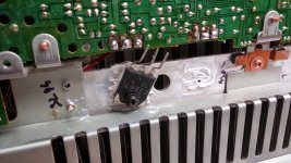
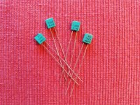
A power amplifier, only with TO39 metal can transistors
(-> this project on my own page, in german)
Some month ago I got a large amount of old unused electronic parts.
Including many transistors in TO39 housing: BC140, BC160, BSX45; also many electrolytic capacitors of larger capacity: 4700uf etc ..
Too good to throw away, so what can you do with it?
I got the idea to build an amplifier with it and only use these TO39 transistors, even for the output devices.
Some might think that's nonsense, but it doesn't matter: here the thing is and it works.

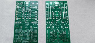
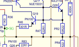
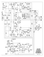
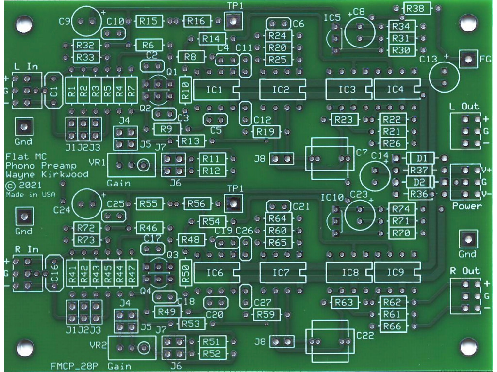
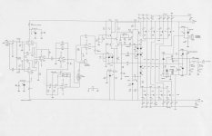
After countless LTSpice simulation runs, I finally made the PCB layouts and had the boards made.
Since you always order several boards, I designed the layouts in such a way that the remaining boards could also be used for "normal" amplifiers, e.g. with TO126 and TO264, SOT-93 or similar transistors. For this reason, the TO39 output transistors sit on their own circuit board.
The capacitors in the parts convolut were all axial, so the power supply board has space for axial and radial smoothing capacitors.


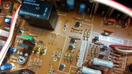
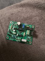
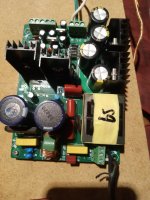
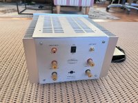
The power supply is regulated and offers a stable voltage of + 20V and -20V.
More is not possible for the amplifier, since the transistors BC140 / BC160 can only withstand 40V.
The supply contains an electronic fuse which switches off the operating voltage of the amplifier if a set current value is exceeded.
There is also an interface that enables the power supply unit to be shut down with an external switching voltage; this is e.g. used by the DC-Protection.

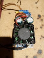
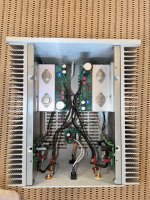
The output transistors are sitting quite close together and have no heat sinks; with convection only they don't get rid of their heat, so a fan is required. Here, however, a very low air flow is sufficient, so that no annoyingly loud, powerful fan is necessary.

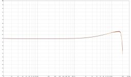
So the amplifier can continuously deliver 30 watts into 4 ohms (per channel) without unhealthy heating.
If someone misses the obligatory small coil at the output: it will later be on the DC protection board; but at the moment the Amp works without it, no problems.
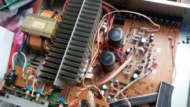
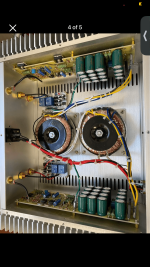
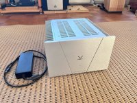
Everything is fitted onto a PVC plate for the function test. The next goal is to make a suitable housing. And, consequently, to replace the SOT-93 series transistors in the power supply unit with the extra board with TO39 transistors.
Here are some more photos and oscillograms.


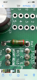
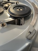
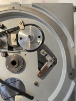
output board assembly:
the resistors for the output transistors are fitted to the downside of the board.
after every new fitted transistor was tested, if they all work as one


(There are 7 PNPs, 8 NPNs on the main board, 20 PNP / NPNs each on the output board, a total of 55 transistors, per channel)
sinus 1000 Hz .......................sinus clipping 1000 Hz............rectangle 1000 Hz..................triangle 10000 Hz
(each with probe head 10:1)


 -> this project on my own page, in german


![20240307_203423[1].jpg](/community/data/attachments/1191/1191010-8497074bd09f1c95158070eb6e734673.jpg?hash=hJcHS9CfHJ)
![20240305_222145[1].jpg](/community/data/attachments/1191/1191013-685b716273e5395b998a2ad66cfba344.jpg?hash=aFtxYnPlOV)