Hi guys,
I’m trying to troubleshoot a noise issue in a digital reverb circuit that’s driving me nuts. Here’s the schematic. Hope you could
Give some advice, I don’t own an oscilloscope and this makes troubleshooting a pain.
I was able to trace down the noise to ADC U201 SDOUT. When shorted to ground, U202 DIN is also grounded and the noise stops.
Grounding U201 /RST resets U201 U202 and U203 and the noise goes away while grounded, but reappears once /RST is high again.
Grounding U201 AINL does not eliminate the noise , therefore I thought the problem was isolated to U201. Replaced it with another cs5340, but no luck. Also thought about this being a problem with the supervisor circuit u205, and replaced the stc809 with a mpc809t but still no luck.
Any ideas??
Thank you very much,
Fran
Attachments
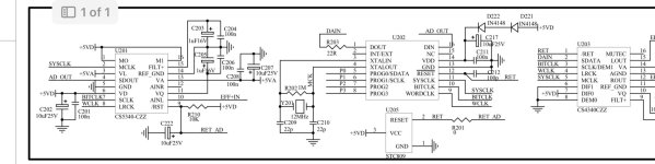
Browsing through https://statics.cirrus.com/pubs/proDatasheet/CS5340_F2.pdf , I see that the AINL and AINR inputs of the CS5340 expect input signals biased around half the supply voltage, so when you short them to ground, you probably drive the ADC into negative clipping. I haven't a clue why that doesn't eliminate the noise while shorting the digital output does.
The full-scale level is about 1 V RMS. Are your signal levels of the order of 100 mV to 300 mV (taking 10 to 20 dB of headroom) at AINL?
There should be an analogue anti-aliasing filter/input driver circuit somewhere. Is there? Without it, interference around multiples of the clock frequency of the modulator of the CS5340 can end up in the audio band.
Thanks Marcel, please see full
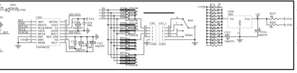
schematic, are U8A and U8b the input driver you mention? I’m troubleshooting this without an input signal (without a guitar plugged , since this is the effects section of a guitar amplifier) And noise is still present
schematic, are U8A and U8b the input driver you mention? I’m troubleshooting this without an input signal (without a guitar plugged , since this is the effects section of a guitar amplifier) And noise is still present
Attachments
Yes, apparently U8A and U8B are the anti-aliasing filter and ADC driver. It looks to me like the anti-aliasing filtering is better than required in the ADC datasheet, but I doubt if driving a switched-capacitor ADC input via a 1 kohm series resistor works well.
What happens when you short the point where R81 is connected to C62 to ground? If it reduces the noise, what happens when you remove the short and place a 2200 pF capacitor straight from the ADC AINL input to ground? It should be a film or ceramic class 1 capacitor (NP0, C0G), preferably not a class 2 ceramic cap.
What happens when you short the point where R81 is connected to C62 to ground? If it reduces the noise, what happens when you remove the short and place a 2200 pF capacitor straight from the ADC AINL input to ground? It should be a film or ceramic class 1 capacitor (NP0, C0G), preferably not a class 2 ceramic cap.
Hi, tried shorting the signal path between r81 and c62 and ground, but noise is still present. Then added a 2n2 cap between adc input and ground, and again no change.
Yes it’s a commercial amp, it worked great until it started making this loud harsh white noise intermittently. Sometimes after powering off /on or resetting the adc it worked fine. Now it always suffers from this. Changing sw4s1 position changes the noise from just a loud harsh hiss to a loud noise with the hiss on it, but there’s always a huge noise floor regardless. Could any auxiliary components around the adc be inducing this noise? The amp is totally unusable as it is now.
Digital reverb is performed with a FIFO buffer implemented in DRAM. The DRAM has failed. It is making errors.
Ed
Ed
it worked great until it started making this loud harsh white noise intermittently.
I see, then my comments from posts #2 and #4 are irrelevant, as I assumed it never worked well.
Have you got any information about U202?
Hypotheses I can come up with:
1. Missing pull-down on AD_OUT causing the ADC to sometimes work with the wrong data format. Unlikely, as the unit used to work properly and this should cause distortion rather than noise, but easy to try by adding 10 kohm from AD_OUT to ground.
2. Broken U202, like Ed suspects. You will probably have a hard time finding a replacement then.
3. Broken DAC. You could test this by removing R203 and connecting AD_OUT to DAIN. Of course you won't get any reverberation, but if the effect channel sounds clean then, you know everything before and after U202 works properly.
4. Some input signal of U202 dodgy, for example unreliable reset (but you already tried replacing U205) or randomly varying PROG inputs due to dirty contacts or loose soldering of switch K4A.
Regarding 4, does switching K4A back and forth have any impact?

Great, that should make it easier to find a replacement if needed!
The BD is only specified for 3.3 V supply voltage, although some inputs are 5 V tolerant, while the AL is specified for 3.3 and 5 V supply. There is some difference in the drawn supply current and apparently the BD uses SRAM and the AL DRAM for data storage, but they certainly are very similar.
The BD is only specified for 3.3 V supply voltage, although some inputs are 5 V tolerant, while the AL is specified for 3.3 and 5 V supply. There is some difference in the drawn supply current and apparently the BD uses SRAM and the AL DRAM for data storage, but they certainly are very similar.
Last edited:
The OP should check that the supply voltages are okay.
The static sound is a sign of memory failure.
Ed
The static sound is a sign of memory failure.
Ed
BD3201 datasheet states this (translation by Google):The BD is only specified for 3.3 V supply voltage, although some inputs are 5 V tolerant, while the AL is specified for 3.3 and 5 V supply. There is some difference in the drawn supply current and apparently the BD uses SRAM and the AL DRAM for data storage, but they certainly are very similar.
"The main difference between bd3201-14A and AL3201 is that bd3201-14A (DRE) uses low voltage (2.7V – 3.3V) power supply, the power supply voltage of AL3201 is 5V, in addition to the power supply, bd3201-14A and AL3201 Fully pin compatible. For customers who are accustomed to using the AL3201 development board with 5V power supply, if they want to use the original To replace AL3201 with bd3201-14A on the AL3201 development board, you only need to add a simple circuit. bd3201-14A can realize 5V power supply (see "bd3201_ ApplicationNote_DifferenceBetweenAL3201_cn.pdf" or contact us)."
Thank you guys, you are awesome.
I found some suppliers of bd3201 from china that would ship to Spain in a reasonable time. I will order one and replace it. Hope this fixes the problem.
In the meantime, will try some further troubleshooting as per your suggestion Marcel.
Switching K4A back and forth changes the flavour of the noise, but noise is always present.
Last edited:
- Home
- Source & Line
- Digital Line Level
- ADC output noise in digital reverb circuit