Case for Ian Canada streamer

I assembled this Ian Canada streamer - the flagship compact #93B. It's come together very well - super easy to put together and sounds absolutely divine in my chain. However, it does look like a Mars lander - which I don't mind, but my family is not a fan of (the kit is in my living room), and I do worry about electrocuting some curious visitor who starts poking the super-caps.

Looking for experiences and advice on putting this in a case. One option would be to just build or buy a case into which this can go as it is - as a vertical stack. The other option would be to flatten it and put some of the boards across with ribbons connecting the GPIOs. Am ok with the mains brick outside - just need the main stack inside the case.

If anyone has built a 3D printed case for the whole stack, would love to get the designs ... or other ideas also welcome.

Attachments

  • IMG_7670.jpg
    IMG_7670.jpg
    401.2 KB · Views: 259

Comparison test DATS vs DATS+REW . Are the values at the left part of the chart OK? or caused by see INFO...

A 2.5 way basreflex loudspeaker floorstander with crossover was tested.

Multiple measurements are consistent and only differ at first impedance peak. 1 Ohm difference. ..Allways... what does this mean? Resister measurements outcomes between the 2 measure methods are the same.
Resister measurements that were done showed expected values and are within range for both methods.

Comparison measurement DATSv3
versus DATSv3 + REW

DATSv3 + REW Red
DATSv3 Purple

1732928666079.png

In REW all values except “the leads resitance value” for the impedance setup were take from the manual DATv3 on a Mac written by olen.

10kΩ for the Rsense value. (based on the value of output resistor) Don’t know my Dats R value

Set Rsense = 10kΩ


100kΩ for Rin (where is this value derived from?)

10mΩ for Rleads. I used 0.7399 Ohm Messured earlier with dats sofware.

For the reference cal I used a 4.952 ohm resistor..


-- INFO -- My version of the DATSv3 is different from olen’s...See earlier post with picture...If my dats series output resistor value differs say 2000 Ohm from the 10000 in olens Manual could that alter the reponse, and then ONLY doing so in the left part of the graph we are seeing?

Thanks I appreciate your input and thoughts..


OS on laptop, Manjaro Linux with Wine installed....Linux version of REW 5.31.3 installed
install
DATS_V3_setup.exe installed with wine installer. (right click install with Wine windows program Loader)
Installation path: home/.wine/drive_c/Program Files/
Open console and type winecfg hit ENTER
In Wine configuration window that pops up click Add application. Go to c/Program Files/DATSV3/ and select en add DATS.exe
In Wine configuration window select the just added DATS.exe and click audio at top window
I chose windows version 7 but other OS may work.
1732929332275.png
1732929392080.png

For the input and output device now there’s the just installed PCM2900C Audio CODEC Analog stereo option to choose. The rest i left at “System default” cause other settings also didn’t add any specific in and outputs. In other words I CAN NOT CHOOSE “SPEAKER” OR “LINE IN” like olen could in the manual DATSv3 on a MAC.

Also in “PulseAudio Volume Control” I chose PCM2900C Audio CODEC profile: analog stereo Duplex
1732929679256.png


When in REW ...for input and output device same CODEC is chosen...in and output were left to default
No option to CHOOSE “SPEAKER” OR “LINE IN” I think I have might have to edit some settings in Manjaro or ad pipewire or jack to route audio ins and outs...If you guys think the measurement is ok I leave it as it is for now.
have a good weekend

Want to power portion on of Marantz amplifier circuit with power supply, but want to avoid damaging my power supply

Marantz 300DC. I have one of these amplifiers and inside the amplifier is a small power transformer mounted in the front. The supplies voltage to these really small power supplies, one power supply for each channel mounted up towards the front.

IMG_4711.jpeg

IMG_4712.jpeg


These little power supplies provide a +/- 70vdc to the biasing circuit of each channel. I would imagine the current draw is pretty low. I made some corrections that were made by somebody that worked on it (no idea who did the work) and on power up noticed that the small transformer got pretty warm. Warm enough that the primary winding is now open.

IMG_4709.jpeg


I’m on the search for a transformer, but before I install a new transformer, I want to see what is going on. I intended to hook up a power supply to the amplifier channel so that I can see how much current is being drawn and make sure I get the circuit working otherwise. That way when I put the new transformer in, it’s good to go. It would be nice to see how much current is being drawn so that I might size the new transformer.

IMG_4710.jpeg


This is the amplifier circuit. You can see the +70 V goes towards the top feeding R723, R724, etc. The -70 V is towards the bottom feeding the collector of Q706, R729, etc.

I got it all hooked up as I was wanting to, and powered up the amplifier on a dim bulb tester. The bulbs stayed bright and I heard a “whirring” noise coming from the inside of the power supply. I immediately turned the power off and checked over things and nothing looked damaged at all. I was curious what the behavior was about. I found that the power supply outputs are shorted when they are turned off. I am seeing about 16 ohms across the outputs. Once I turn the power supply channel on the short goes away it course.
IMG_4708.jpeg


I am guessing this is the source of my problem. I thought I would come here for advice before going at it again. I’d really like to not damage this power supply nor the amplifie lol.

The next go, having everything hooked up I’m guessing I should have the +/-70 V turned on before powering up the amplifier? Obviously, they normally turn on at the same time when you’re using the original transformer inside of the amp.

Another thought I had was maybe wiring a diode in series, maybe a 1N4004 or 1N5404. Something to eliminate the short that the amplifier sees. I checked for backfeeding voltage at the points, where the power supply would hook up, but there was no voltage coming from the amplifier itself, which leads me to believe it was just the short it was seeing.

Would love some encouraging advice.

Thank you,
Dan

Lab Gruppen FP3400: Mosfet sub needed

I'm working on a Lab Gruppen FP3400 with shorted outputs in one channel. My list of collateral damage includes Q1, which the service manual lists as an IXFN73N30 N-Channel enhancement mode Mosfet, but the actual fet installed is the APT30M40JVR. Regardless, neither of these are readily available from my usual sources, so I'm looking for sub suggestions. IXFN102N30P perhaps? 🤔


A20TDH02 schematic.jpg

IAN CANADA TRANSPORTPI DIGI II Ultra Low problem 3V power supply!

Hello friends
and @iancanada
I recently finished my first raspberry audio player with Sw Volumio.
Rpi4 4GB RAM
IAN CANADA UCPI Universal Ultracapacitor Power Supply Board for Raspberry Pi
Power supply: Toroidal transformer 2x 9V 5A
Power supply so far by one branch from IAN Canada 5V
Display: 7.9inch Capacitive Touch Screen LCD, 400×1280

Today a new sound card arrived:
IAN CANADA TRANSPORTPI DIGI II Ultra Low Jitter Digital Audio Interface Module.
https://www.audiophonics.fr/en/dac-and-interface-modules/ian-canada-transportpi-digi-ii-p-19555.html


IMG_20241129_141908399.jpg

IMG_20241212_233726841.jpg

Does anyone recognize this?

I bought this sub for cheap and I'd like to make better enclosure for it. But I can't figure out what model this is (tried reverse image search and one reddit post but no conclusion) and I have no way of measuring the t/s parameters now. So can someone identify this or tell me how can one measure the t/s parameters for cheap.
Or the not best option, could someone say what could be good ported box for this based on the sealed that it came with?

Thanks

IMG20241211161239.jpg
IMG20241211161531.jpg
IMG20241211161537.jpg

Small DIY 3D printed 3-way speakers for small alcove

I'm going to design and 3d print 3-way speakers to install on the sides of a TV.
Either active or passive crossovers. I have the tools to measure and make both.

The TV is 90degree wall mounted at the end of an alcove, which is about 2m wide and I'll sit on a bed, close to a wall, about 2m from the TV/speakers.
The height between the bed and ceiling is about 1.5m.

I currently have some spare SB19ST tweeters, a pair of Omnes SW 5.01 woofers and for midranges I have:
2x Tang Band W2-2243S
4x Peerless TC9FD00
4x Peerless TC6FC02
4x Peerless TC6FD00
to choose from.

I'm currently thinking of designing a waveguide for the sb19st and maybe for the mids.
Then I'm leaning towards an MTM with the TC6FC02.
And I've already designed and simulated the base for a T-line for the SW 5.01:
1733970118065.png
1733970310370.png


The reason I'm thinking of 3-way is because the SW5.01 is a pretty heavy midbass with a lot of xmax, so I don't know if it could cross over well with the tweeter.

Now my biggest concern is with the waveguide/horn for the tweeter and the placement of the midranges, to get the best sound in the small alcove.

I know it's not going to be perfect in any way, but I'm thinking I should try and make the speakers have a narrower directivity, to not get as many reflections.

I know MTM makes the vertical dispersion narrower, but I'd also want to make the horizontal dispersion narrower.
Should I just place 4x mids in a cross pattern?

Or should I make a unity horn with the mids?
Like the UICW: https://www.diyaudio.com/community/threads/unitized-image-control-waveguide.319698/
I'd use this one, but it's just a little large and I don't see anyone measuring both the vertical and horizontal dispersions, and I think it plays too wide.


Or should I just give up and live with the reflections?

I have a 32x32cm 3D printer so the design possibilities are pretty limitless.

For Sale Speaker set for the SEAS Classic MK2 kit from Troels

SOLD

Hi all
Selling some very good speakers for a project Troels developed -the SEAS Classic MKII
2 SEAS Prestige CA22RNY H1471-08 midrange - used, as good as new SOLD
2 SEAS Prestige MCA12RC H1304 woofers - new SOLD
2 SEAS Prestige 27TFFC H0881-06 tweeters - used, with brand new membrane voice coil units includ new front panels SOLD
Current retail price around 770 euros
Asking for 380 Euro plus shipping
Info: http://www.troelsgravesen.dk/SEAS-3-Way-Classic-mkII.htm

Attachments

  • SEAS Classic MKII.jpg
    SEAS Classic MKII.jpg
    459.3 KB · Views: 71
  • CA22RNY.jpg
    CA22RNY.jpg
    242.2 KB · Views: 59
  • MCA12RC.jpg
    MCA12RC.jpg
    147.3 KB · Views: 64
  • MCA12RC_2.jpg
    MCA12RC_2.jpg
    286.4 KB · Views: 58
  • Seas27TFFC.jpg
    Seas27TFFC.jpg
    274.7 KB · Views: 67

3eAudio DSP as Active Crossover in DIY Class D Amp

Greetings Friends. I have a DIT Class D amp I build according to this guide from IEEE Spectrum a few years back and it's been sitting on a shelf since I got into tubes. The amp has a 2x70w module from 3eAudio and their 2-in-4-out DSP based on ADAU1701.

IMG_20241211_091026564_HDR.jpg


Awww. my first amp.

Anywho, Now I build fancy tube amps and this poor guy is neglected. Alone. But smart and strong. I'd like to make him part of a hybrid Tube-Class D system. I have a little EL84 SE amp with glorious highs and poor bass. I'd like this amp to provide the bottom end.

I would like to program the DSP to be a 2-way Active Crossover, to send the lows to the Class D module and send the highs to a pair of output jacks for a 2nd amplifier. I have a pair of speakers with Bi-Amp capability, want to hear the magic.

I want to add a master volume control to the front end. I plan to add a 100k Log pot to the front panel and run the input directly to that, then to the DSP. Outs 1&2 will go to the onboard amp, Outs 3&4 will go to a pair of RCA jacks on the back panel.

There are 3 pots on the DSP. Crossover Frequency, Onboard Amp Volume, Bass Boost?

There are many projects out there for the Sigma Studio, is there one suitable for this? I suppose I could just watch the video where the guy builds a 2way from scratch...

thanks for taking a look!

w

Dahlquist DQ 10

I just grabbed a couple of Dahlquist DQ 10s for 200 Canadian is there a thread on this forum that can assist me with the subject of rebuilding them and potentially modifying the crossovers and possibly adding a passive rad to the back of the base cabinet I just registered on this site today so I’m not familiar with it my apologies for posting my question in the wrong section if I have done so

Attachments

  • 77238CE0-55D2-41DE-810C-4959B3484166.jpeg
    77238CE0-55D2-41DE-810C-4959B3484166.jpeg
    480 KB · Views: 524

new SCHALMEI feedback

I got a new SCHALMEI feedback:
The schalmeis can't keep up with the horn of a Klipsch, but that's not so bad.
These are satellites and they need support down below.
Previously only for cinema use, the 18 inch corner horn has now been integrated.
The speakers are now connected to my Cayin tube amplifier and are separated with a second-order crossover from 80 Hz. The corner horn is connected to the tube via a high-level input (Reckhorn A409). At first the Fostex 206 were installed but these were replaced by TANG BAND W8-1772 and now I am very satisfied with my satellite system.
I didn't know this dynamic before and the details were overwhelming at first, but now this system is the measure of all things for me.
I've recently had a pair of active Dynaudios (16800DM) with me and they can only do a little more in the treble, so kudos to your design.
1734033974930.png

Looking for opinions on which oscilloscope to go with

For about the last 10 years I’ve been using the same Rigol DS1102E. It’s alright, a decent two channel 100 MHz scope that gets the job done. About 4-5 years ago I got an old Tek 7603 with a couple 7A18 inserts and 7B53A trigger so that I would have an analog scope, but definitely use the digital for most everything.

I guess I’ve just become bored with the Rigol and was wanting to get something new, something with a bigger screen maybe. I’ve had my eye on a couple of the new Rigol 12 bit models, wanting to stick with 100 MHz or higher and wanting to go to four channels the options I was looking at were in the 700ish to 1000 range. Like the DHO924s. The DHO814 can be had for just under 500, has 100 MHz bandwidth and 4 channel, but not sure what is being given up at that price point.

Well, this past weekend was a local electronics get together/ swap meet. It happens twice a year here. I’m a vendor there so I get to go a day early to setup if I wish and also two hours early the day of to get first dibs on what I like before the public is let in. A good friend of mine also has a table there so he came early and knew I was looking to get a new scope. He has a buddy that also has a table there and only sells Tektronix equipment. He was a Tek engineer and service member (Tektronix was started in Oregon about an hour from where I live) and though retired is the go to for any Tek repair in the area. Anyways my friend saw a scope he was selling and I took a look at it. He offered it to me for a substantial discount on what he had it priced and if I was going to buy it I wanted to do it before the general public was let in. There were hundreds of people in line to come in. So I grabbed it.

It’s a Tek TDS 684A, 1 GHz, 5GS/s 4 channel scope. I paid 250 for it, it functions perfectly and is in fantastic shape, screen is nice and bright and the front panel is pretty much perfect.

Is it an upgrade from my old Rigol? absolutely. It feels to be much better quality. I saw the original price of this scope and was shocked. Cost as much as most cars. Will I ever use the 1 GHz bandwidth, probably not, but I don’t know.

So thoughts? I’m sure I could easily get my 250 back out of this scope. I see there are broken examples that sell for more. It’s approaching 25-30 years of age, somewhere in there. It has a smaller screen then the new Rigols, but I also got it for 1/3 the cost and in some ways it specs better. Should I keep the money I saved and put
It towards a new analyzer or power supply and keep this new (to me) Tektronix scope or sell the scope and spend the extra money needed for a new 12 bit Rigol?

Would love opinions
Thank you,
Dan

Your opinion on the parts I choose for my DIY Bluetooth speaker 2.1

Hello everyone,

My project is coming to maturity but before ordering everything I would like your opinion on my project.

Components :

HP + AMP :
  • Subwoofer 4 Ohm : Tang Band W5-1138SMF
  • 2x Full Range 4 Ohm (Re 3 Ohm): Dayton Audio RS100-4
  • Amplifier: AIYIMA Bluetooth amplifier TPA3116, 2.1 audio card, 2x50W for satellites, 1x100W for subwoofer. Link: https://a.aliexpress.com/_EQYXqNI
  • All connected by 2.5mm speaker cables

POWER SUPPLY :
  • Dayton Audio LBB-5v2 (5S with 5 26650 3.7V 5000mAh units), which will supply the amp with 21V in principle
  • charging via a USB C port that I'll plug into the back of the box

DIMENSIONS :
  • 18mm MDF wood
  • for the two satellites, each will be insulated in a sealed enclosure, dimensions based on parts express recommendations.
  • for the Woofer 6,6L with a Bass reflex of 2,5cm on approximately 14cm.

CROSSOVER :
No crossover, the subwoofer output on the amp cuts at 250Hz, and I'm using the full spectrum on the Full Range satellites, not particularly ideal but the sound should be pretty decent according to my simulations. There will still be a bit of dispersion at the top end of the spectrum, but a tweeter isn't in my budget!

I take all opinions and answer questions, so don't hesitate to ask!
One of my doubts concerns the impedance of the 4Ohm satellites (Re 3Ohm). Wouldn't I be better off with 8 Ohm?
And if you have any idea of the autonomy I can get with this battery pack, that would be great!

Thanks a lot!

Crossover question?

I ONLY have my old DS-215-8 woofer , can't afford much more.
I am using a dome tweeter crossed over at 2K presently.

What I am curious about is the implementation of the (4th order LPF ??) and the 10R/22uf/2mH (notch filter).
The tweeter Xover is straight forward and works out in the calculators , but the 4th order is a mystery ??

MTG designs - https://www.mtg-designs.com/diy-speaker-plans/flex-8 -
has the PCB and schema to use this old woofer in what looks like a valid HQ design.
I am about to collect all the various iron core inductors and NPO caps for the woofer side of the Xover.

Is this strange implementation the "secret sauce' to tame the 1K-3K response of the LF driver ?
None of it works out in any online calculator but the result looks nice (below 2).
I might have better 15-20K with my properly padded dome tweeter , but I'm a little bit in awe of
this xover's complexity - would love to know how it works besides just being to identify the sections ??

PS - I'm running it now with just a 2K 2nd order on the woofer - sounds a bit bright in the vocal range.
REAL loud SPL 110+ , still a bit bright mids (but real clear) .....

I was running old (mission domes) at 1.2K - blew one of the tweeters !!

OS

Attachments

  • Flex-8 DS215-8 Schematic 5-10-23.jpg
    Flex-8 DS215-8 Schematic 5-10-23.jpg
    43.2 KB · Views: 142
  • Flex-8 DS215.jpg
    Flex-8 DS215.jpg
    78.9 KB · Views: 134

Questions about IEC inlet filters, again...

Hello,
I was looking at some commercial IEC filters with an intention to clone them. My understanding is that even if the schematics are available, the lay out and actuall construction might be critical for performance so this would be a good reason to buy the ready products. But my little research left me with more questions about how to choose them. In particular, among the models for different current consumption, the only thing that change is the inductor's value: as the current goes up inductance goes down. I suppose it has to do with inductor's saturation but anyway how do we choose the proper filter for a given device? If, for example, the current consumption is at 1A then filters rated at 3A and 10A would perform differently?

I also found datasheets stating inductance at a certain frequency. What would that mean? Does inductance change with frequency?

impact of frequency response humps and nulls

I read somewhere that a hump around 600 hz will sound boxy and that more stuffing can help with that or a rise around 3000 may sound strident and needs a resistor what are some other freqency response deviations and the effect and solution. Just curious and I spent quite a bit of time looking for this information and really cannot find much. I have a average 5 db dip between 100 and 200 at the listening position not sure what this causes or how to fix it.

Sony CDP-557ESD Clock Help

Hello, I need some advice regarding an old battleship Sony CD player I recently purchased. At some point in its life, it had a Trichord clock upgrade but this has been removed. I'd like to return it to stock but it's missing the original crystal oscillator. I know the frequency I need (16.9244M), but I don't know if essentially any crystal will do the job? A quick web search throws up a ton of results for oscillators, are they pretty much all the same?
I'll have to replace the components around the original crystal as they've just been snipped and left in place, other option is to try to get another external clock and pick up a DC supply from somewhere in the player.
Any advice would be greatly appreciated!

For Sale ACA MJ Racam pair UK

For sale a pair of ACA MJ Racam built these on a wim and have collected dust since first test, please see photos.

R1/R2 on one board arnt raised above the board so could probably do with replacement and the washers holding down the fets could do with being replaced but everything else is good.

I would recommend setting up again before use.

UK mainland only

£90 ono This will include Postage to mainland UK
20241130_154032(0).jpg
20241130_154049.jpg
20241130_154057.jpg
20241130_154101.jpg
  • Like
Reactions: arteom

Vintage console enthusiast here with a strange transistor project

Hey everyone.

Iam a big fan of the old transistor based consoles especially Neve 80 series consoles and the sound of them, I have nerded out on designing my own modules and now I want to take it a little further and use some of my old 1:12 transformers, to make a mic preamp. but with a transistor amp.


Iam looking for transistor based schematics for mic preamp that can use a 1:12 winding input transformer. If it has ever been made.
I know a 1:12 ratio winding would be made for tube amps. But I wonder if anyone back in the days 60’S/70’S made any mic pres in consoles for that type of transformer, that was transistor based.
Or also someone nowadays who made it would be of interest.


Let me hear if you heard about such thing or what your thoughts are on the idea.
Thanks
Kind regards Bob

Need help to identify an amplifier

can anyone identify this tube amp , i want to restore it and i need a schematic , i think it was used in some type of tone cabinet , there is no markings on it other then 2222 printed on the front of it . power tubes are supposed to be 6l6gc , other tubes are 6c8 , 6c5 , 6h6 , 5u4 rectifier ,
the power transformer is branded STANDARD RADIO PRODUCTS OF KITCHENER ONTARIO CANADA .
Please let me know if you know what it is.

Attachments

  • TONE CABINET TUBE AMPLIFIER 001.JPG
    TONE CABINET TUBE AMPLIFIER 001.JPG
    564.1 KB · Views: 193
  • TONE CABINET TUBE AMPLIFIER 003.JPG
    TONE CABINET TUBE AMPLIFIER 003.JPG
    582 KB · Views: 191
  • TONE CABINET TUBE AMPLIFIER 009.JPG
    TONE CABINET TUBE AMPLIFIER 009.JPG
    688.7 KB · Views: 183
  • TONE CABINET TUBE AMPLIFIER 005.JPG
    TONE CABINET TUBE AMPLIFIER 005.JPG
    635.6 KB · Views: 173
  • TONE CABINET TUBE AMPLIFIER 008.JPG
    TONE CABINET TUBE AMPLIFIER 008.JPG
    588.2 KB · Views: 176
  • TONE CABINET TUBE AMPLIFIER 012.JPG
    TONE CABINET TUBE AMPLIFIER 012.JPG
    629.7 KB · Views: 167
  • TONE CABINET TUBE AMPLIFIER 011.JPG
    TONE CABINET TUBE AMPLIFIER 011.JPG
    637.3 KB · Views: 186

8" Woofer/Subwoofer Intermodulation Distortion Testing

I have found that low Intermodulation Distortion is a good indicator of sound quality. The last couple of years I have been measuring 10-12" subwoofers and 6-7" midwoofers in IMD, I will now share some testing in 8" drivers.

The test enclosure is a .5 cu ft (14 liter) sealed box with the bottom lip of the speaker just 2 inches above the floor. The microphone is on a stand 49"high with the base of the microphone 33" from the driver. A distance of about 1.5m from the speaker to the microphone. As I'm not measuring in an anechoic chamber my measurements are not comparable to anyone else's but comparisons can be made between the drivers I test.

Feel free to make suggestions on what drivers you want to see tested.

Behringer A500 _ one question about the schematic

Hi i have one Behringer a500 unused on which i would like to replace all the electrolytics with better parts The stock ones are scaring
The nice things of this unit are balanced inputs and a decently sized toroid (i know nothing about its actual quality)
i am attaching the schematic
I read of some distortion issues for different position of the input attenuators
Looking at the part of the circuit

1733908074136.png


i see a strange R71 and surprisingly a pot value bigger than the input impedance at the opamp
I always thought that the pot value should be lower of the following stage input impedance
Can i eliminate R71 at least ? i dont like it at all
Thanks a lot

Attachments

Feedforward Error Canceling with Blameless Topology

Feedforward Error Canceling, in theory, could cancel most of the distortion. You could get 0.002% THD figure without much efforts with this technique, at least in simulation. A good example is the famous Current Dumping. If you don't know how Current Dumping works, I highly recommend you jump to this thread to learn how it works and what it can achieve. Current Dumping with OPAMP

Besides Current Dumping, the same technique, Feedforward Error Canceling, can also be implemented to other topology. Here I use a Blameless style amp for example.

See the example below, the Blameless style with EF2, with an average loop gain. Pretty common setup. Please ignore C1 and R7 for now. They will be used later. The idle bias is at 136ma. 10KHz 20Vp into 8 Ohm is about -72 dB THD.
1733284878887.png


To implement Feedforward Error Canceling, you need pull a resistor from Miller cap VAS side to the inductor speaker side. However, the VAS doesn't have the capability to drive the feedforward resistor directly. The work around is to create TMC (Transitional Miller Compensation) around the driver stage, and use driver stage to drive the feedforward resistor. See updated circuit below. R13, R4, C1 create a transitional network for the Miller compensation.
From the simulation, you can see all the distortion is gone!!.

The optimal value of R7 depends on the inductor value and also the loop gain bandwidth of the amp. The loop gain bandwidth of the example below is about 600KHz. Thus, the optimal value of R7 should be 2 * pi * Bandwidth * L = 2 * 3.14 * 600,000 * 4.7e-6 = 18 Ohm. If you still don't know what is going on, please search Current Dumpling and learn it. This technique is highly effective but also overlooked.
1733285800920.png


[EDIT]
PS: In the example above, there are 2 things going on. One is TMC, the other is the feedforward error canceling. They both contribute to lower the THD. The TMC may cause other stability issue. I recommend to check the final version that is without the TMC.

Some turntable suspension measurements

I’m playing around with a suspension for my new plinth and did some rough measurements of the two options that others might find interesting. In the plots below Z is up and down X& Y are horizontal. “springs” are a set of metal springs from a VPI HW19 “With Damping” means with the original VPI foam inserts in the springs. “Foam” is mixed cell polyurethane designed for building or machine foundation isolation. “Constrained” means that I built a solid wrap in the XY dimensions from plywood about 80% of the height of the foam blocks. I calculated the size of the foam blocks from the manufactures literature and should be getting a resonance close to what I get with the springs but I think the manufacturer’s data is based on wide thin sheets and the shape I am using (essentially a cube) is changing things a bit. One thing you can’t see in the roughly 1 second of data I posted for each is that the undamped springs rang for an incredibly long time, minutes in fact. The vpi foam inserts while they did raise resonance a bit cut the ringing time considerably.

Attachments

  • Foam Constrained.jpg
    Foam Constrained.jpg
    232.8 KB · Views: 254
  • Foam Not Constrained.jpg
    Foam Not Constrained.jpg
    223 KB · Views: 254
  • Spring No Damping.jpg
    Spring No Damping.jpg
    147.8 KB · Views: 249
  • Springs With Damping.jpg
    Springs With Damping.jpg
    139.9 KB · Views: 272

DIY Fostex Laboratory inspired project questions

Hi all, first post on this forum!

I am embarking on on a new project with a friend who is a skilled cabinet maker with access to cnc etc to build some speakers inspired by Fostex lab studio monitor series.
https://www.preservationsound.com/2013/09/fostex-laboratory-series-pro-audio-monitors-c-1980/

The plan is to use the plans for the h400 horn available here: Here is construction plans for Fostex Type of H400 wooden horns - Techtalk Speaker Building, Audio, Video Discussion Forum make out of Sapele and match with a modern 1 inch comp that is suitable (any suggestions welcomed - thinking BMS 4550 or B&C 250)

and build a LF box inspired by this matching cab from the 80s:

https://www.fostexinternational.com/docs/speaker_components/pdf/recom_enclose/w300aII_encl.pdf

but modify for B&C 12NDL76 rather than the original Fostex driver, which I have done here = Subwoofer Box B&C Speakers 12NDL76 | Ported Box | Slot .

Planning to run as low as possible and cross at 800hz as per the original design - to the horn then run a super tweeter from 7k up, (Fostex FT17H?). Does my design look suitable for this?

Not confident in crossover design but have used lots of DSP in live sound scenarios, but would rather run passive from one amp rather than active with DSP on 3 amps so need to work that out. The original crossover plans for the H400/Wa3002 combo are available, how much would it cost to get give someone a list of the drivers I am using and the old crossover plans and get them to make a passive crossover? Thinking Crown macro tech amp(s).

Thanks in advance!
  • Thank You
  • Like
Reactions: GM and wchang

For Sale Various Jantzen/Mundorf/others capacitors and coils

Most components are new or used for tests. See photos for details:


Jantzen Air core coils:

1.2mH, 1.6mm, 0.27 ohm, 30x60 mm, 550g, SOLD


NEW: Nihicon KW 2200uF 63V capacitors, new, bought from Mouser, 15 EUR/set of 8 x1


Send PM for details. Price is per piece + post costs, Payment via Paypal.

Attachments

  • Jantzen caps.jpg
    Jantzen caps.jpg
    459.5 KB · Views: 349
  • Jantzen coils MKII.jpg
    Jantzen coils MKII.jpg
    865.1 KB · Views: 326
  • Nichicon KW.jpg
    Nichicon KW.jpg
    516.4 KB · Views: 182

new member

Hi, I'm Henk from the Netherlands. A long time ago, I was probably 12 years old, I started building amplifiers. I used the DIY kits from Philips for that, I built preamplifiers, a complete 8-channel mixing console and power amplifiers. In that period I also started building speakers.
When I was 18, all that building was a bit over, I was too busy with my studies and work. I was already working in security at the time and built the central units myself for various large projects.
Now a few years ago, before my retirement, I started building speakers again, for example the Klipsch Cornwall (Klonwall). About 2 years ago I started building Horn speakers from Western Electric complete with separate crossovers. These are now finished and I am very happy with the sound that comes out of them. I also bought a tube amplifier (so not built) during that period, the Willsenton R8 and I was very happy with it until I saw a video from Stephe (Skunkie Design) about modifying this amplifier. I did most of the modifications then. A few days ago I had some problems with the amplifier and then I sent Stephe a message which she promptly answered and of course was able to solve my problem, through Stephe I also came into contact with DiyAudio. I hope I can learn more about building audio equipment here.

Noise measurements for LiFePo4 and supercapacitors?

Hi all,
I've been searching around without any joy for evidence of noise measurements of modern batteries or supercapacitors when used as power supplies for digital circuits.
I can see older references and measurements for lead acid and nicad batteries in various articles and in threads like this Battery-powered supplies - diyAudio
But I can't see anything similar for supercapacitors or for example LiFePo4 batteries.
I've heard very good reports from people using lifepo4 with a float charger to power their dacs, but I'd like to understand some of the theory and benefits.
Is anyone aware of any publicly available results comparing lifepo4 to other methods of low noise power supply?
Thanks,
James

  • Locked
New Members... please read this before posting

Welcome new member,

Start a thread here and introduce yourself to activate your forum posting privileges. Please save your technical questions for another post. The Moderation Team will approve your introduction, if you would kindly allow us a little time for this to happen we would appreciate it.

Please note, we are an English speaking forum. Posting in the forum's legitimate sales area is restricted until new members have built up a small count of quality posts elsewhere on the forum. This is done for the protection of both new and established members.

We're looking forward to learning about your journey and how we can help you.


diyAudio
Moderation Team

* Threads other than introductions created here, and other non-complying posts may be removed or other such action at the discretion of moderation.

looking for schematic for prewar Gibson EH150

I am looking for a schematic for a 1935-36 Gibson EH150 1st Generation second series amp. I've been asked to bring it back to stock but it came with a 5U4 rectifier, 5V6 and 6V6 power tubes, and a 6A6 preamp tube. I know the 5V6 and 6V6 can't be right and the 5U4 rectifier is a question mark. It looks like the amp was recapped in the 60's and the tech who did it splattered solder all over and did a really bad job. Does anyone know where I could find a schematic? This is a very early amp with no volume control or any pots at all. There is a resistor on the one input jack and a cathode resistor but that is all. There is a choke, a field coil speaker, and a lot of dust. Any help on a schematic would be fantastic!

Attachments

  • cache_935945284.jpg
    cache_935945284.jpg
    65.9 KB · Views: 351
  • cache_935945306.jpg
    cache_935945306.jpg
    40.8 KB · Views: 336

Can anyone identify these output transformers?

I bought these cheap off ebay. Seller said 10K ohm-4,8 Single End Transformer. Quite Large and heavy. I would guess Chinese.
Just thought someone here might recognise these. 200 for the pair so the impulse kicked in LOL. He mentions Yaqin but I'm not sure
about that. Thanks

Attachments

  • output transformer 2.webp
    output transformer 2.webp
    232.8 KB · Views: 86
  • output transformer.webp
    output transformer.webp
    134.7 KB · Views: 88
  • IMG_4655[1].jpg
    IMG_4655[1].jpg
    462.1 KB · Views: 81

Endgame WMTMW open baffle woofer options

I am still not finished building my monster OB line array speakers but am already looking ahead for a next build

1000003215.jpg


My next build will run also use a ESS Heil tweeter >3khz
The mids will be two alpair 12p's

For the woofers I am eying the 21" Lii Song OB drivers. Problem is there are 2 versions from 2 different Lii Songs.....

Version A

1000003244.jpg
1000003245.jpg


Version B
1000003241.png
1000003243.jpg


Version A has higher QTS and QMS and dual voice coil.

Version B has vented pole piece, higher VAS and thicker plates and looks a little more premium to me, even though it is slightly cheaper.

Which one would you pick and why?

Attachments

  • 1732265013561.jpeg
    1732265013561.jpeg
    210.4 KB · Views: 83

W5-876SE for MTM

I purchased six Tang Band W5-876SE 16 ohm woofers on closeout from Parts Express several years ago and never got around to doing anything with them. I'm thinking about using them for MTM speakers. I've searched around quite a bit and have found many posts that mention that they can be used for MTM but no specific info on how to best go about it. Where should they be crossed and what type of tweeter would be work with them? Are there any existing designs? I'd also consider some kind of TL enclosure if that would sound substantially better. They'll mostly be used for music.

On the search for cheap mods to my setup

Hi there,

I registered here, because it seems the only place where people are discussing multiuple things from my current setup.
I want to give and get some feedback about minor modifications that I have planned.

the speakers: https://www.diyaudio.com/community/threads/panasonic-sb-pm28-active-crossover-help.301156/
and the crossover: https://www.diyaudio.com/community/...uit-diagram-for-a-weah-d222-crossover.406079/
for this setup I use a SMSL AD18 Amp.

Best regards

For Sale 2021 DIY Sony VFET - VFET N Channel (pt 2)

So I was one of the lucky ones to be able to build and own one of a few hundred 2021 DIY Sony VFET amplifiers as pre built (OS) and tested by mr. Pass.
Now, due to significant downsizing, basically losing a hobby/listening room due to family expansion, I put this amplifier up for sale.

IMG_20230919_072934.jpg

IMG_20230919_072904.jpg


IMG_20230919_072915.jpg


IMG_20230919_072922.jpg


The amplifier is the N-channel version, see link to build thread. I have built it fully as stock and the Meanwell SMPS is included. In the past two years I have had the amp playing compression drivers on Yuichi Horns from 600hz and up. The sound, well this forum will back up it's qualities 🙂


Please send me your best offer + shipping and paypal fees from The Netherlands. I'd rather have this amp making someone happy than it being not in use at my place but if it does not meet my price, I will keep it as the collectors item it is. 🙂

RIAA preamps versus real loads

On another thread I proposed several sophisticated RIAA preamps, adding LTSpice simulations for all or most of them.

One of the main problems in simulating RIAA preamps in any program is that you have to add a load that includes both the anti-RIAA and the cartridge.

The one I found the most interesting one was an opamp representation of an idea Erno Borbely had proposed years ago in The Audio Amateur magazine, in a discrete preamp design e introduced there.

The RIAA part of the preamp was split in two preamps: the first one being passive and the second being active.

So with the help of some DIYAudio friends, which I hope show themselves here, it was arrived to working preamps with excellent simulation specs.

To start showing models and sims, I will start by what I consider a brilliant development by Hans Polak to the original proposal by EB.

It is to be noted that also MarcelvrdG contributed to this design.

Attachments

Cable Management.

I've seen a lot of kit on many forums, but often it comes with a lot of visible cables.

This may be quite acceptable to those contributors, but it's quite easy to hide most of them if you choose.

I'm a tidy person, so I don't like to see them. They can also be a trip hazard, more of a problem, if something expensive then gets dragged off a stand when it happens.


I use plastic trunking. it's dirt cheap, easy and quick to fix, either with a few small screws or just the adhesive that is on the back.
Mine sits on top the skirting boards and is hardly noticeable. Of course, any change of equipment can be accommodated as the tops just clip on and is easily removed and replaced.


Now I know this won't interest many, but perhaps it will some.

Cables from one double socket feed the TV and everything under it to the left and the wall unit lighting and all my audio equipment to the right.


[IMG]


[IMG]

This feeds my electric piano, its amplifier and the music stand lamp.

[IMG]


There are two pairs of cables to each of these jukebox wall boxes, which have quick release connectors behind them. The cables pass down inside the trunking below the shelf, then along more trunking on top of the skirting board, then disappear behind the wall unit.

[IMG]

This trunking comes in different widths and lengths, here in the UK, usually in 3mtr lengths for just a few pounds. Easily cut with a small saw. You can get "elbows" for them but they aren't really necessary.

[IMG]
  • Like
Reactions: Miller-8

AlmaAtaKZ just joined, Hoping to build my first pair of speakers

Hi, all!

Just joining. Starting with saying thank you to user DannerD3H for making a guide for Hypex HFD newbies. Really appreciated!

Have just started building a pair of active speakers using FA253 and having no prior experience of any design or build.

Anyone wants to coach me through this project?

Denis
London

Simulating and modifying the UDP3

G'day Guys,

I've been playing around with Mark Johnson's UDP3 in LTspice.

Firstly to understand what its doing and secondly to modify it to my purpose.
1730793988818.png
I don't understand the 2nd stage clamped capacitance multiplier entirely and I can't find a model for the AZ431AZ so that I can simulate it.
From what I can figure out the purpose of this subcircuit is to set the output voltage at 19v (aside from the reduction in ripple).

I would like to be able to use the UDP3 for input voltages other than the specified 22vac and output voltages other than 19vdc.
With this goal in mind it seems like the clamped capacitance multiplier subcircuit should be modified or dropped to allow the extra flexibilty.

I've whipped up a sim in LTspice however I am very new to simulation so please forgive me if things are not done well.

I have omited everything up to and including the rectifiers as unimportant for the work at hand.
I have also omited the ferrite beads as I can't figure out how to sim them properly. I don't think these are very important for the sim anyway.
I couldn't get a model for the TIP122 to work so I am using the model for the TIP142 as close enough for my purpose.
So starting with the first capmx stage, here's what I have come up with.
Sim1.png
For 25vdc in, I am getting 3v drop which seems reasonable.
With a 0.35Vrms input ripple. I am getting 3.4mVrms out.
40db reduction in ripple according to my calculation.

2 stage.png
Adding a 2nd stage the same as the first drops another 3v and gives me ripple so low I can't see any in the sim even with the scale set to pV.

So a couple of questions to get the ball rolling.
1)Are my assumptions reasonable so far?
2) Is 350mVrms a reasonable ripple voltage for something like a 150mA load
3) Is there a way to figure out what the ripple is in the sim when it is so low the line is flat on a 1pv scale?

I would like to figure out what improvement in ripple reduction would be from adding a second stage.

My main use case for this circuit will be as a 'pre-regulator' before a VRDN style denoisered LM317/337 in place of a CRC filter.

So the ultimate question is:
If one was to simply chop off the clamped capacitance multiplier and put it in front of a denoiser, is there much benefit to adding a 2nd capmx stage?

DSP Three-way open baffle

Hi there - I was kicking around the idea of making a Pure Audio Project (PAP) clone using an 8" full range with 2 15" woofers...but the x-over had me ruffled. I've never built a speaker or cross over and wasn't sure I wanted to tackle it. Plus I'm not completely convinced a FR will give me the top end I want so I was thinking of adding a tweeter/super tweeter of some kind. I was also thinking about trying to add Dirac room correction to my system. Then recently I've been reading about how far class D amps have come, and maybe thinking of trying something in that vein. Enter miniDSP's new FlexHTX; eight channel dsp with Dirac built in--talk about flexibility. So, and bear with me here....consider an active three way PAP clone using the FlexHTX as the cross over. Drivers would be two Bianco 15" drivers, a Tang Band W8 full range driver in the middle, and some sort of AMT or Ribbon tweeter mounted next to the full range, NEO 3 for example or Mundorf ($$). Amplification would come from two three channel Purifi based class D amps like Buckeye or one of the other similar ones out there. I'd run the woofers up to 400hz, the tang band from 400-8k or so and the tweeter from 8k up. With the functionality of the Flex I can do all the x-over work digitally, time alignment etc and room correction. I'd still have two channels in the x-over left over for subs if needed. I'm confident I can build the open baffle.

What do you all think of this idea? I don't love being bound to using the miniDSP's DACs...but to be honest DACs are all getting pretty damn good and the idea of getting the cross over "right" plus the in-room correction probably makes up for whatever shortcomings the onboard DACs might have.

What am I looking for? Big, open sound, excellent imagine, dynamics, clarity. Music is a wide range but mostly country rock (Grateful Dead, Bill Strings) and 80s rock and small group be-bop jazz. Really looking for that big immersive soundstage I hear people describe from open baffles without giving up the dynamic impact of high sensitivity speakers.

I'd have to liquidate most of the existing rig to fund something like this, and I don't love putting pre/dac/x-over all in one box but maybe that's the ludite in me. I keep reading/hearing great things about the clarity and transparency of these class D amps and seriously considering taking the plunge in this direction. Tell me what you think!

LDR Pre MkII - LDR volume control and I/O switching

The list of differences between LDR Pre MkII and original VxD LDR volume controller is so long that I thought it might require a new thread, even though LDR Pre MkII is actually a spin-off of amazing VxD from Vincent:

Arduino based LDR volume and source selection controller

1) Instead of Arduino Nano which runs on Atmega328P, LDR Pre is driven by Atmega328PB which can be found on some Chinese Arduino Nano clones. To utilise however the full power of "PB" which has three native 16 bit timers instead of one, Nano clone boards require hardware modification to expose additional pins on "PB", as well as new bootloader which uses serial1 instead of serial0.
2) LDR Pre has native 16-bit "DAC" capability, instead of 8-bit DAC in VxD. This allows smooth volume changes without impedance range switching which was causing volume bumps due to time constants in RC filters at PWM outputs.
3) LDR Pre supports only OLED with SSD1306/SSD1311, no LCDs any more. OLEDs from Aliexpress running on SSD1309 are not supported - I was not able to make them work over I2C.
4) LDR Pre has firmware which stores all the parameters in EEPROM.
5) LDR Pre fw has ability to change all the parameters from user interface, including: load and nominal impedance, screen brightness, screen saver timeout, welcome message, I/O names and LDR min values, max saved volume level, measured 5V voltage, etc.
6) Entire user interface is accessible by a remote or encoder. You can use only one of them or both to access all functions.
7) Backlight pin is now used to control power amp relay
8) Entire board runs on 5V. Built in Nano 5v regulator is not used any more, so less heat on the controller board. OLED now draws current from power supply directly instead from Nano.
9) Power supply is now delivering 4X5V instead of 2X12+8V.
10) There is no feedback code to maintain constant current in LDRs. I found this routine to cause more instability in impedance than environment temp, so I removed it. This allowed more room for additional functions.
11) Since all the parameters are stored in the EEPROM, it's possible to deliver unified, one-size-fits-all precompiled firmware updates without involving Arduino IDE and all the hassles it carries. There is no need to have IDE installed at all to update firmware or change parameters.
12) Calibration routine has been changed and optimized to accommodate 16-bit timers.
13) There is an option in the menu to reset all parameters and names to default values.
14) Firmware is power amp friendly - it can be configured not to save volumes above max value stored in EEPROM. By default this value is 10 (out of 50).
15) Firmware boots into standby mode. Pressing play button on remote for 3 seconds turns on the device and powers up the power amp (if connected). Pressing it again for three seconds puts the device in standby mode again and turns off the power amp stage.
16) Pressing center button on (Apple) remote or encoder for 3 seconds enters the setup menu.
17) There is now a child lock in the firmware, which allows to disable encoder and operate with remote only.

Attachments

  • IMG_4928.JPG
    IMG_4928.JPG
    466.5 KB · Views: 4,128

XKi - X's ab initio Karlson 6th Order Bandpass

Update (5/21/2020): My Plans for XKi W5-2143 here.

Update (4/17/2019): xrk971's W5-2143 XKi (more info here):
750221d1555471376-xki-xs-ab-initio-karlson-6th-bandpass-xki-w5-2143-p08-jpg


Videos here: https://www.diyaudio.com/forums/ful...tio-karlson-6th-bandpass-127.html#post6689070

XKi W5-2143 basic design here.. It is very important to follow all the instructions in previous link showing internal build details regarding use of melamine foam damping pads and felt and foamcore on the backside of the aperture.
143 here.

Update (3/23/16): Srednivashtar's wonderful dual PA130-8 XKi

An externally hosted image should be here but it was not working when we last tested it.


465542d1423880510-xki-xs-ab-initio-karlson-6th-order-bandpass-xki-rs100-stereo.png


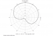
What's the deal with a Karlson aperture in front of the driver? Won't that mess up the polar dispersion? That's a great question, and no. The aperture actually improves the uniformity of the polar response compared to the bare faced driver:

461843d1422331652-xki-xs-ab-initio-karlson-6th-order-bandpass-xki-rs100-4-tape-neweq-polar.png


This thread found its beginnings here: A Speaker that Kicks Butt in Large Spaces - Page 66 - diyAudio. The finding was interesting enough that I decided to put it on its own here.

I will recap:

Properly scaling the Karlson K15 cabinet to work with smaller drivers has been an elusive goal for over 50 years. If you are at all familiar with the K15, you know that the moment it is scaled below a 12/15 scale, the bass extension suffers. The cabinet excels at efficiently controlling cone motion and channeling what little motion there is into high SPL levels, albeit, with some warts in the way of the famous Karlson "W" dips and peaks in the mid-bass region. Nonetheless, the speaker sounds very good and has a devoted following.

I recently have been working on developing 6th order bandpass subwoofers over in the subwoofer forum, especially slot-loaded push-pull bandpass subs. This alignment is very good at controlling cone motion and in many ways reminded me of the topology of a K15. So I got to thinking that I could develop a K15 style cabinet for any size driver, if they satisfy some basic T/S parameters needed for a 6th order bandpass box (moderate to low Qts, low Vas, strong motor, high sensitivity, etc.). I would design the new box from the ground up, or as they say, "from the beginning". The "i" is for ab initio, or from the beginning. I have figured out how to design a new type of "K" box with deep bass, good cone control, for any size driver with appropriate T/S parameters. There is no scaling of the K15 design involved, and it begins with the design of a 6th order bandpass alignment optimized for bass extension, flat response, and good control of cone motion, all properties that a 6th order bandpass alignment is known for. The difference is that the output port is simply a Karlson aperture of appropriate cross sectional area, and the chambers are designed with angles to avoid rectangular volumes that may have resonance modes.

As a test case, I designed a box that can reach 50Hz using a nominal 3.5in driver - the Dayton RS100P-4 (paper cone). This driver has a suitable moderate Qts to allow fb to set below fs and has good xmax of 4mm and a relatively powerful motor. The 6th order bandpass design was a 4.0 liter rear chamber and 1.0 liter front chamber with a 0.5in x 5.0in x 9.0in long vent, and a front chamber vent consisting of a 5in dia aperture.

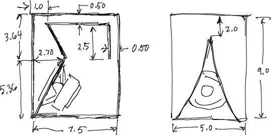
I converted these volumes and vent dimensions into a box that has internal dimensions of 5in wide x 9.0in tall x 7.5in deep which then provides the correct volumes once the vent volume and driver volumes are subtracted. The front K-aperture is sized to have the same cross sectional area as a 5in dia hole, which was approximated by the area of a triangle that is 5in wide x 7in high, accounting for the curvature and offsets near the bottom.

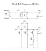
The box design looks like this:

461029d1422021961-speaker-kicks-butt-large-spaces-k15i-rs100p-4-plan.png


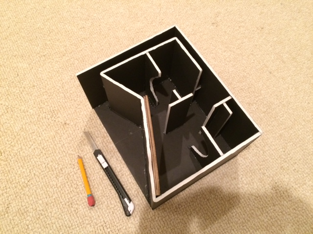
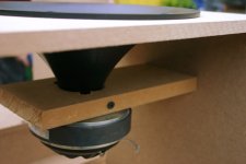
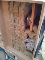
Here is a photo of the inside during construction showing the bracing and folded vent arrangement leading to the top of the front chamber (although not ahown, there is a piece of open cell foam on the bottom and I put a wad of pink fiberglass in the main large volume to damp the HF's from reflecting back onto the rear side of the cone):

461030d1422021961-speaker-kicks-butt-large-spaces-k15i-rs100p-4-build-01.png


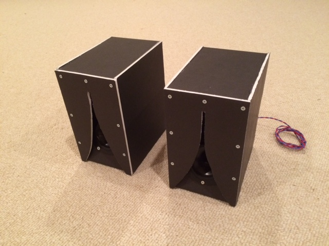
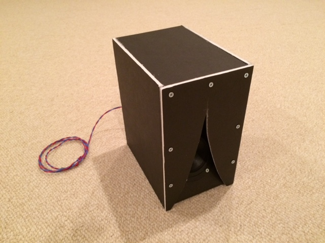
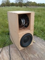
Here is the completed speaker - still retains the look of a very small K15:

461031d1422021961-speaker-kicks-butt-large-spaces-k15i-rs100p-4-build-02.png


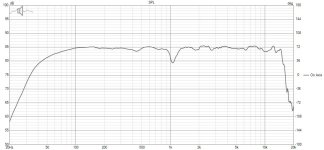
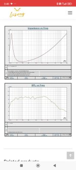
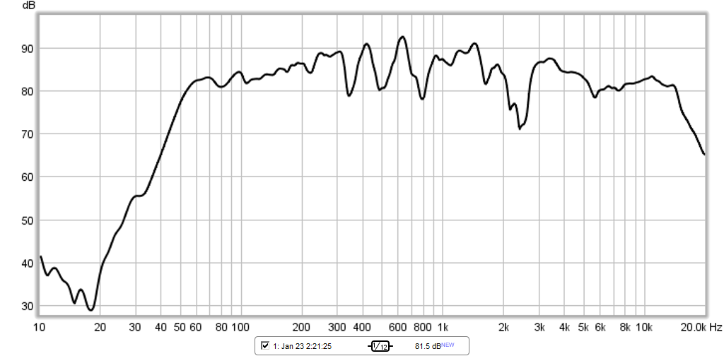
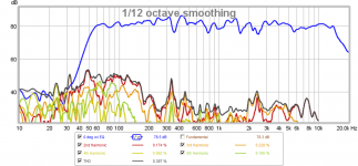
And here is the measured frequency response about 0.5m away along the axis of the driver centerline - it has the characteristic Karlson "W" dips and a falloff near the bandpass followed by the direct radiator output which lets it reach up to the HF limit of the driver (about 14kHz in this case). The measured f3 is 51Hz! An amazing concept for anyone who has ever tried to scale a K15 down will realize. Predicted max SPL at 4mm xmax is 98dB in 2pi space:

461032d1422021961-speaker-kicks-butt-large-spaces-k15i-rs100p-4-meas.png


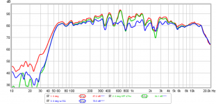
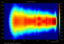
How does it sound? Very nice - sound clips attached below. Dispersion was very good as evidenced by the polar data showing very little variation in the response from 0 deg to 45 deg (or 90 deg full cone, and even out to 60 deg the variations are quite small). This is one of the biggest advantages of the Karlson aperture is a uniform polar response:

461170d1422071148-xki-xs-ab-initio-karlson-6th-order-bandpass-xki-rs100p-4-polar.png


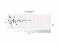
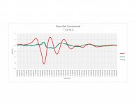
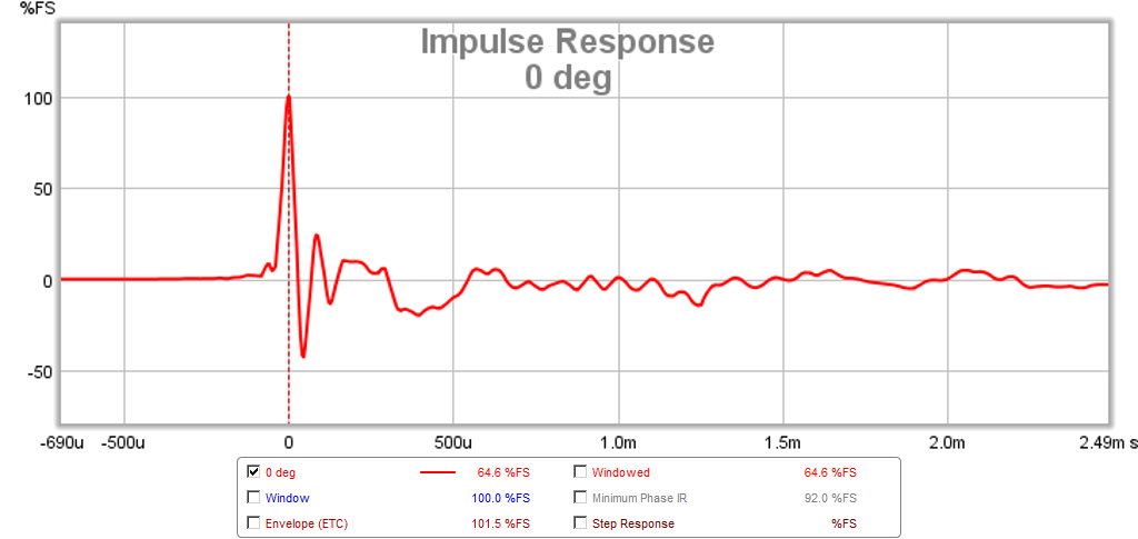
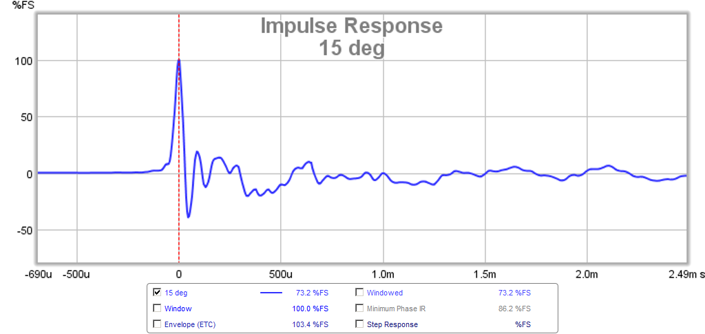
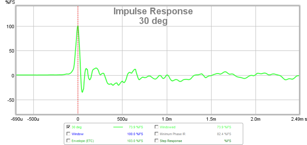
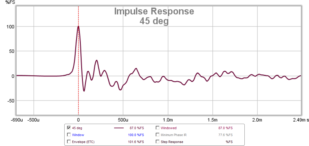
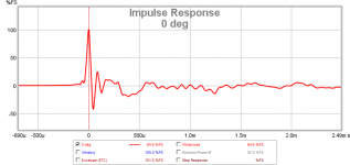
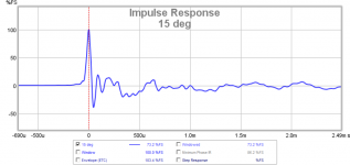
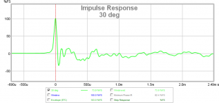
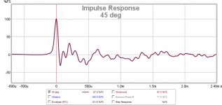
The transients are also clean as you can see from the measured impulse response. Furthermore, because the polar response is so uniform, the impulse response is also uniform along different angles. Many open face speakers will exhibit vastly different impulse responses because they have beaming or cone breakup modes that are angle dependent.

Here are the IR's for 0 deg to 45 deg (note the similarities from 0 deg to 45 deg):

461171d1422071148-xki-xs-ab-initio-karlson-6th-order-bandpass-xki-rs100p-ir-0-deg.png


461172d1422071148-xki-xs-ab-initio-karlson-6th-order-bandpass-xki-rs100p-ir-15-deg.png


461173d1422071148-xki-xs-ab-initio-karlson-6th-order-bandpass-xki-rs100p-ir-30-deg.png


461174d1422071148-xki-xs-ab-initio-karlson-6th-order-bandpass-xki-rs100p-ir-45-deg.png


This is a tiny speaker with a tiny driver, but it sounds quite big. Now, the neat thing about this methodology is that if a 3.5in driver can hit 51Hz, a 6.5in or 8in can probably do 40Hz. This can also be used for a sub woofer with a good pro audio 12in driver like the Faital Pro 12HP1030 and achieve 120dB SPL and mid 30Hz...

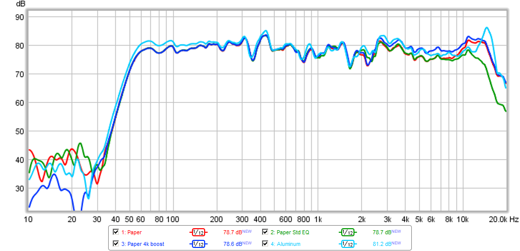
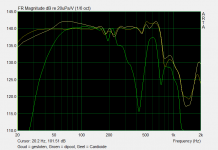
I applied a -24dB/oct high pass filter at 47 Hz to reduce cone excursion and some EQ to see if we can't make the response less bumpy. Here is the result of the HPF and EQ:

461175d1422071148-xki-xs-ab-initio-karlson-6th-order-bandpass-xki-rs100p-effect-hpf-eq.png


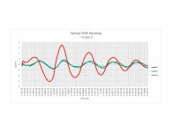
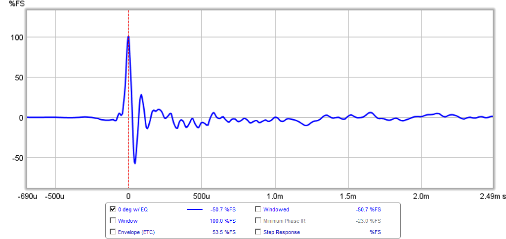
Here is the impulse response after the EQ has been applied - a little cleaner:

461176d1422071148-xki-xs-ab-initio-karlson-6th-order-bandpass-xki-rs100p-ir-eq.png


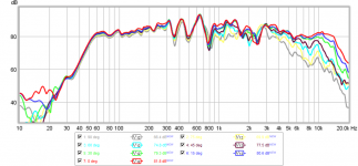
Here is the harmonic distortion - a lot of this is the result of the foam core cabinet vibrating. CLD can knock this down quite a bit but I have not done that yet:

461179d1422071148-xki-xs-ab-initio-karlson-6th-order-bandpass-xki-rs100p-hd-eq.png


If you are interested in this speaker and would like to design a box around your favorite driver, follow along and I will detail the process and methodology for designing the XKi for your driver.

Briefly, the process starts with a design of a quasi 6th order band pass box with your favorite driver, but with these guidelines:

1. Set the rear chamber volume to front chamber volume ratio at 4:1
2. Set the output vent to have a cross sectional area equal to at least 2x Sd if you plan on using full range drivers
3. Using a quasi 6th order bandpass simulation program (Akabak, Bassbox, etc) adjust the vent length and chamber total volume to provide the optimum balance of bass extension, SPL output, and flat response.

Akabak script for 6th order band pass is available here: XKi - X's ab initio Karlson 6th Order Bandpass - Page 16 - diyAudio

4. Convert the volumes and vent length to a box with a total volume equal to 5x the front chamber volume PLUS the driver magnet/basket/cone volume and the vent volume
5. Set the width of the cabinet based on driver bezel width plus an inch or so of margin, set the height at an aesthetically pleasing ratio (golden ratio is good), Fibonacci, etc.
6. Calculate the depth based on known volume and height and width
7. Calculate the front chamber volume using the area of a triangle - this calculates the setback of the angled V in the front chamber.
8. Make the vent a channel vent leading from the top to the back and wrapping down. Note that the final build tends to have a deeper tuning than predicted due to the additional losses in the narrow aspect vent walls, so you may want to reduce the vent length by about 15% or so in the build.

Edit Jan 25, 2015: effects of EQ, high pass filter, and aluminum vs paper cone - aluminum cone seems to have more bass.
461443d1422174486-xki-xs-ab-initio-karlson-6th-order-bandpass-effect-paper-alum-eq-boost.png


Edit Feb 19, 2019: Plans for XKI with PA130-8 by Thermcul
717369d1542949252-xki-xs-ab-initio-karlson-6th-bandpass-pa130-8-xki-box-drawing-png


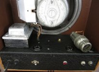
xrk971's As-Built XKi for W5-2143:
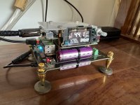
846117d1590078184-xki-xs-ab-initio-karlson-6th-bandpass-xki-w5-2143-plans-xrk971-21-2020-jpg

Attachments

  • xki-rs100p-4-polar.png
    xki-rs100p-4-polar.png
    120.4 KB · Views: 15,714
  • xki-rs100p-ir-0-deg.png
    xki-rs100p-ir-0-deg.png
    50 KB · Views: 14,982
  • xki-rs100p-ir-15-deg.png
    xki-rs100p-ir-15-deg.png
    51.1 KB · Views: 14,857
  • xki-rs100p-ir-30-deg.png
    xki-rs100p-ir-30-deg.png
    52.1 KB · Views: 14,810
  • xki-rs100p-ir-45-deg.png
    xki-rs100p-ir-45-deg.png
    59.2 KB · Views: 14,749
  • xki-rs100p-effect-of-hpf-eq.png
    xki-rs100p-effect-of-hpf-eq.png
    96.9 KB · Views: 14,917
  • xki-rs100p-ir-eq.png
    xki-rs100p-ir-eq.png
    43.7 KB · Views: 14,630
  • XKi-RS100P-4-RP-01.zip
    XKi-RS100P-4-RP-01.zip
    932.1 KB · Views: 686
  • XKi-RS100P-4-ZB-02.zip
    XKi-RS100P-4-ZB-02.zip
    944.7 KB · Views: 515
  • xki-rs100p-hd-eq.png
    xki-rs100p-hd-eq.png
    169.8 KB · Views: 16,315

WTB WTT for SONY K82

I find myself in possession of most of the parts for a 2016 SONY VFET amplifier.

I picked up PCBs here that were populated originally for use with K60/J18 devices…of which I have a few.

However, in searching for a pair of the special mounting brackets used with this amp project I also acquired a pair of J28 KF33 VFETs here in the swap meet.

They were originally from
CircuitDIY Acronman according to the seller.

Not curve traced. No Vgs written on them. I’d have to figure out the testing procedure to determine Vgs.

Still, I’d like the opportunity to assemble the amp as NP originally designed it.

To my knowledge NP never curve traced the VFETs. My understanding is he measured the Vgs of the devices and then I suppose he tried to put together pairs of the K82/J28 that would avoid any serious operational problems in the circuit.

I’m looking for a pair of K82 that would work with the J28 KF33 I have properly in the circuit.

I’d be willing to buy them outright or would consider other options such as trading for some of the K60/J18 devices I have which are perfect for the SONY VFET Part 3 OS project.

I would also consider buying K82/J28 pairs if there is someone who has them from a reputable source that never got to building with them.

Again, I don’t feel obligated to have curve traced matched pairs.

In the event that someone does have some special curve traced matched pairs of K82/J28 and they are interested in a trade then I might consider offering some Semisouth R100 curve traced matched pairs that I have hoarded in exchange.

Dynaco ST80 clone - Speaker wobble on start up

I have cloned a Dynaco ST80. The only circuit changes are 6800uf filter cap and output caps. My issue is that there is 3v of speaker cone deflection on start up and I can’t shake it. 3v DC measured across the outputs for a split second. Have added a 100nf x cap to the live and neutral. This actually helped a little bit as the deflection is now silent. Any ideas? I have an original ST80 and it behaves the same way. Would still like to fix it. Would an NTC thermistor help?

Filter choke critical inductance

For a good design in power supply filtering for audio (tubes) I read that one must take into into account several parameters, including the Lc that is the critical value of the input inductance. This is true when using an LC filter, where Lc>Rl/6*pi*f, but the same can be neglected with a pi-filter, CLC. Since I'd like to use a relatively small filter choke, someone could explain this rule (and the role of the input C)? Thanks.

Trying to see FFT of a typical tube gain stage

Hi

Everyone says that triode tubes have more 2nd harmonic THD than anything else and I wanted to see this in LTspice. I made a CC gain stage with typical values and ran it with a low-level sine input. The output was generally clean looking and THD was pretty typical from what I've read.

The FFT of the output showed odd and even harmonics with the 3rd not being much lower than the 2nd. A few higher harmonics were present in both FFTs. I know the curve for a triode follows a 2/3 exponent, which maybe does produce both even and odd harmonics?

I wondered what the input signal looked like and its FFT was similar AND its THD baseline was only a little below the baseline for the output FFT. This made me wonder if the tube was simply amplifying the dirty oscillator harmonics?

I went to a different file for a super-low-THD solid-state amp and checked its input and output FFT. In this case, the baseline for the output FFT was around -180dB and 10dB lower for the input.

So, it seems like LTspice scales the THD of the sine generator depending on the range of THD the circuit under test generates?

Does this seem normal?

Thanks

Full range cardioid

Full range cardioid, need advice on next prototype

Currently i'm working on a new speaker build, aiming for a cardioid radiation pattern from 50Hz on up. I have made a prototype consisting of a top cabinet which has a A&D R1030 10" woofer in a damped Uframe, and a Hypex PSC 2 400 plate amp (2 ch amp + dsp). I experimented with the opening of the Uframe, adding slots and especially the placement and quantity of damping material. See attached files for the optimal polar pattern. For high frequencies, I have a B&C DE250 on a Dayton 10” waveguide. I modified the waveguide slightly to accept the bolt on compression driver and remove any irregularities in the transition to the waveguide.

For the sub cabinet, I have 2 Peerless XLS10 woofers and a Hypex PSC 2 400. In order to achieve cardioid radiation, I have combined a sealed and dipole enclosure. The dipole is high passed at 50Hz using a 4th order filter in order to limit cone excursion and to have the advantages of a pressure source <50Hz. Free field measurements showed a polar resembling cardioid from 63Hz on up.


However, there are some points for improvement for which I would like your advice!
1. In order to achieve maximum suppression of LF at rear, I had to delay the monopole sub by 1,9ms. This resulted in less than optimal summation of the two drivers at the front. The dipole woofer is actually positioned 20cm behind the woofer in the sealed enclosure.
2. The polar has a maximum which is about 20degrees of center, caused by asymmetric construction of the dipole. I think I will make a new version using a regular H frame.
3. I’m considering adding passive radiators to increase output of the monopole <50Hz for LFE use. I’m a bit concerned this will complicate achieving cardioid radiation in the 50-150Hz region.

Attachments

  • Cardioid sub.jpg
    Cardioid sub.jpg
    813.9 KB · Views: 5,586
  • B&C_DE250.jpg
    B&C_DE250.jpg
    399.9 KB · Views: 5,205
  • Gesloten_dipool_cardoid_respons.png
    Gesloten_dipool_cardoid_respons.png
    9.3 KB · Views: 4,995
  • Prototype_Cardiod_sub_80Hz_polar.png
    Prototype_Cardiod_sub_80Hz_polar.png
    38.9 KB · Views: 4,898
  • Sonogram_B&C DE250.png
    Sonogram_B&C DE250.png
    152.7 KB · Views: 4,937
  • Topkast.jpg
    Topkast.jpg
    718.4 KB · Views: 2,258
  • Sonogram_woofer.png
    Sonogram_woofer.png
    116.6 KB · Views: 2,216

RK-Auto200W Amplifer

RK-AutoBias200 Amplifier

Here's a schematic I've been developing for a couple of months, now. I have not laid out the PCB yet, let alone built one.
[The schematic shown in post #92 is the most recent iteration so far.]

The design goal is a 200W amp with distortion below 0.001% up to 20 kHz. VCCP/VEEP looks like they're going to be +/- 63V unregulated. VCC/VEE will be +/- 70V regulated.

Generated rails from the shunt and series-pass regulators will be
VCCP-5V
VEEP+5V
+15V
-15V

I've made an attempt at EF-triple stabilization, with a thread here: Removing MJE1503x in an Output Triple
but I don't think the final answer to that can be found in sims. I have not drawn the feedback yet, nor the final compensation. In IC op amps, a cap from the top of R8 to GND is sufficient, but a T-miller arrangement here will further linearize the output stage.

OL Gain is very high, and the pole from the output stage will between 10 and 20 MHz.

Output transistor biasing will be adapted from William Chater's bias control circuit from 1988. That's what's in the yellow box. I've detailed my adaptation here:
William Chater's "Bias control for power amplifiers," Revisited

Added, 10 Mar 2020:
My plan is to finish this design, documenting my progress and performance on diyaudio. When the design is complete, and the PCBs are laid out, I will make PCBs available. Gerber files, too. Then I will try to stick around to give advice on building and mods.

I still have some expectation that simulated performance, up to 20 kHz can be as low as 0.001%. We will see if my PCB layout skills can get a real circuit to approach that performance.

At this point in my life, I have 35 years experience as a designer of audio circuits, including 12 years where I designed discrete transistor power amplifiers for car audio. After that, I designed class-B and class-D audio amplifier ICs for 10 years. Now, I am a research engineer designing analog to digital converters for 200 GS/s SERDES in silicon processes that are not yet released for production.

I'm hope this design ends up being as good as the best of what's out there, both commercially and DIY.

Outline of the thread, so far:
  1. Addition of cascode below Q5. Discussion of TL431 and replacing with quieter infra-red LEDs--posts #8 - #15
  2. First documentation of performance--posts #15 - #28
  3. Simulated amplifier with clipping. Quasi-sat of KSA1220 driver caused instability exiting clipping. Replaced drivers with 4 each of KSC3503 and KSA1381. This let me increase UGBW to 5 Mhz from 3 Mhz, and increased SR to 94 V/us from 58 V/us. Posts #39 - #45.
  4. Documentation of simulated performance, post revision, Posts #46 - #50.
  5. Discussion with BesPav about my design decisions, Posts #62 - #65.
  6. Addition of SOA limiting, single-slope, dual slope, and eliminating distortion caused by SOA circuit, posts #66 - #78.
  7. Schematic of SOA limit and bias servo offloaded to daughter PCB, post #80.
  8. Replaced LM334 with "ring of two" current source, post #85.
  9. Find sources of distortion and optimize. TPIIC considered. Posts #92 - ...

-----
keywords: [special=power amplifier]%[/special], [special=design ]%[/special], [special=folded cascode]%[/special], [special=triple EF]%[/special], [special=LTspice]%[/special], [special=low THD]%[/special], [special=low noise]%[/special], [special=self bias]%[/special]
.
AutoBias200.PNG

SA9123 USB to SPDIF optical I2S output 24BIT 192K SA9227 32BIT 384K AC3 DTS DSD256

It may be the cheapest in the world. And the excellent performance of 24 BIT 192K
USB TO digital platform. SA9123

SA9123 USB TO SPDIF ,optical , I2S 。
The SA9123L is a high performance up to 24bit,
192KHz PCM streaming USB High-Speed compliant
audio steaming controller. It features one IEC60958
S/PDIF transmit streaming output. The SA9123L is
ideal for both one stereo-in and one stereo-out
professional digital audio interface applications
The SA9123L is high-performance, up to 24 bits,
192KHz PCM Streaming USB High Speed Compatibility
Audio USB controller. It has an IEC60958
S/PDIF transport stream output. SA9123L Yes
Perfect for one stereo input and one stereo output
Professional digital audio interface application
Supported specifications:
Independent sample rates for each
pair
44.1/ 48/ 88.2/ 96/ 176.4/ 192 KHz sampling rates
16/24 bit resolution
--------------------------------------
It may be the cheapest in the world. And the 32BIT 384K DSD256 with excellent performance
USB TO digital platform. SA9227
And supports AC3 DTS and DSD256

Attachments

  • SA9123-02.JPG
    SA9123-02.JPG
    263.3 KB · Views: 426
  • SA9123-03.JPG
    SA9123-03.JPG
    293 KB · Views: 425
  • SA9123-4.jpg
    SA9123-4.jpg
    80.4 KB · Views: 436
  • SA9123-5.jpg
    SA9123-5.jpg
    71.2 KB · Views: 403
  • SA9123-6.jpg
    SA9123-6.jpg
    82.4 KB · Views: 377
  • SA9227-02.JPG
    SA9227-02.JPG
    344.1 KB · Views: 360
  • SA9227-03.JPG
    SA9227-03.JPG
    269.8 KB · Views: 388
  • SA9227-04.JPG
    SA9227-04.JPG
    58.6 KB · Views: 375
  • SA9227-05.JPG
    SA9227-05.JPG
    149 KB · Views: 404
  • SA9227-06.JPG
    SA9227-06.JPG
    139.7 KB · Views: 429

Cancelling out room Eigentones with a sub & DSP-LF

I have an annoying boomy resonance in my listening room at about 68Hz. I don't want to insert any filters into the signal path to my amp (Q909).

My speakers are Magneplanar MG1.6 and go low enough but can't be relocated to a position which doesn't excite the eigentonesso much.

So I was pondering on placing an unused sub near my listening position driven with a Dayton Audio DSP-LF and spare amp. In this case, adjusting the response to cancel out the boom rather than boosting the low frequencies.

Doable?

Car stereo subwoofer? With this amp?

Hello everyone!

First, I want to apologize if the translation is bad, being French I use a translation site to put everything in English, if things are mistranslated or incomprehensible, let me know 🙂

So I will explain my situation, I always wanted to have a subwoofer in my car, so I went deep into the search.

At first I wanted a closed subwoofer of 300/350W RMS, except that in the end, given the prices for such power in closed box, I preferred to go on bass-reflex or other because it is much cheaper.
Except that I realized that the dual subwoofer drivers were not so much more expensive than single sub driver. So I decided to start with that.

Then came the choice of an active or passive housing. I found some nice active sub (price/power level), but when I looked a little more closely, I saw that the integrated amps were not necessarily ideal (example: barely 2x50W RMS for a 2x300W RMS sub driver), so I have a first question: Why is it so different? Can we trust the active sub?

Sub in question: Edge Car Audio DB EDB12TA-E0 (2x 300W RMS)

Integrated amp in question: ED7300

Personally, I concluded that it was not, so I started looking at the passive sub.

That’s when I thought: since I plan to take dual subwoofers, it is better to put them on stereo, so I have a second question: Is it really worth it? I read that we perceive very badly the stereo with bass and most of the time, they were mixed in mono, except that I want to dream!

I have always been very sensitive to the pan (left/right variation) on instruments, and as far as to make as much have the best sound possible! (I really want to believe that the stereo is worth it, but if not, so be it ...)

Finally, to return to the sub, I found one that interests me strongly in view of its price, but especially that in the manual there is an instruction (screenshot support) to connect it in stereo (which I did not find in the manual of its lower version the B1 210):

1733767114172.png

Sub in question: GAS Mad B2 210

It is therefore a 600W RMS, or 2x300W RMS.
Looking at the 300W RMS dual channel amps in 4 ohm, I came across amps at 300 € minimum! In any case, too expensive for me.
Then I went to a second-hand amp and came across this one:

Amp: TN4 900D

Only 40€! With 4 channels 2 ohm and 2 channels bridged 4 ohm to 450W RMS. My main question being: can I make a stereo installation by connecting the 2 sub drivers with 1 pair of channels bridged 4 ohm 450W RMS each?

I read somewhere that it is not possible stereo in bridge because the 2 signals (stereo right side and stereo left side, I do not know how to describe this) add up to form a mono signal at the end. Talking with an AI (GPT chat) I may have learned that actually the 4 channels of this amp (and probably for all amps if it’s real) are in fact separate on the stereo right side and stereo left side.

Then I wondered if there are 2 right and 2 left channels, so why not make two pairs of the same side (right + right and left + left) instead of making two pairs with 1 different side (left + right x2)? And then make a stereo installation?

Does it make sense? I don’t know much about it, it may be lunar for connoisseurs. Thank you for enlightening me!

If something is misexplained/mistranslated, I apologize and will do everything to clarify it 🙂

PS: at the base I was going to take 2 used amps at about 300/350W RMS in 4 ohm rather than a multicanals amp but since I came across this really cheap amp I wonder what is best. And if it is possible, is 450W RMS per subwoofer driver not too much for 300 W RMS?

So you want to design your own speaker from scratch!

You have been doing this DIY speaker thing for a while, probably built a couple of proven designs from people like Zaph , Troels Gravesen, Paul Carmody or any number of other successful designers.

Perhaps you started out like me, cobbling together random drivers with off the shelf or textbook crossovers, but never quite worked out why they didn’t work out as well as you imagined. You bought books like David Weems' “Designing Building and testing your own speaker system” and Vance Dickasons "Loudspeaker Design Cookbook" and have decided it is time to design something from scratch.

Alternately you may have followed AllenB’s excellent tutorial "Designing Crossovers Without Measurements" but have decided to take it to the next level and do measurements in which case Joseph D'Appolito's book "Testing Loudspeakers" and his article "Testing Loudspeakers, Which Measurements Matter" will be useful.

If you haven’t done any of the above you may want to have a look at Paul Carmody’s excellent FAQ "Proven Designs" first, which covers why you should build a proven design as your first project .

If you have got this far and are still game then read on 😉

Note that I am not an expert, I am just a guy who has been playing with speakers for the better part of 30 years, I’ve learnt quite a lot just by experimenting, a lot from reading and I’ve probably forgotten at least half of what I at one point knew or understood (or thought I understood!!).

As I don’t have expertise in all areas (some might claim in any!) I’m thinking that I will put in a number of placeholder posts, with the idea that members with more experience in those areas can write a post and I (or another Moderator) can paste the content into the relevant placeholder post. I’m also happy for this to be more of a live thread with suggestions for corrections or additions to the core posts taken on board and potentially amended.

There are many different design philosophies, and it is not my intent to try and cover them all, though where appropriate different directions may be suggested. I’m not interested in starting any religious wars on design choices 😉

The intent of this thread is to give someone a starting point and things to think about rather than a prescription on how to do it. I am an advocate of simulation as part of the design process so later posts will feature this, but even if you don't want to simulate hopefully you will still find the thread useful.

So lets get started!

Lets keep this thread uncluttered, A separate Designing your own speaker from scratch discussion thread has been created.

Please use that thread for questions and discussions or suggestions and we will try and add just relevant content to this thread 🙂 non complying posts may be mercilessly moved to the other thread 😉
.
  • Like
Reactions: fabio323ti

For Sale Marantz CD-273 for sale

Asking price: 165 € + postage, EU buyer preferred due to customs.
Working condition. With the legendary Philips TDA1541 DAC inside.

Attachments

  • 20241206_115955.jpg
    20241206_115955.jpg
    315.2 KB · Views: 45
  • 20241206_115916.jpg
    20241206_115916.jpg
    249 KB · Views: 44
  • 20241206_115903.jpg
    20241206_115903.jpg
    252.5 KB · Views: 46
  • 20241206_115838.jpg
    20241206_115838.jpg
    264.3 KB · Views: 41
  • 20241206_115823.jpg
    20241206_115823.jpg
    295.6 KB · Views: 47
  • 20241206_115738.jpg
    20241206_115738.jpg
    309.9 KB · Views: 44
  • 20241206_115702.jpg
    20241206_115702.jpg
    290.2 KB · Views: 46
  • 20241206_115642.jpg
    20241206_115642.jpg
    292.6 KB · Views: 42
Projects by fanatics, for fanatics
Get answers and advice for everyone wanting to learn the art of audio.
Join the Community
507,633
Members
7,881,216
Messages

Filter

Forum Statistics

Threads
405,912
Messages
7,881,216
Members
507,633
Latest member
kwong1