Go Back   Home > Forums > Blogs

Old

My wiring scheme for the O2 in a B3-080 Desktop case with RCA's and 1/4 inch jack

Posted 5th July 2012 at 04:23 AM by MrSlim
Updated 5th July 2012 at 04:26 AM by MrSlim (fixed typo)

When I was planning the wiring scheme for the Baby Desktop O2, originally, I thought I would use 3 and 4 pin board mounted posts with equivalent pin connectors so all the flying wires could be disconnected from the board. I realized that would be too much work(and probably even more prone to disconnection so I only made one of the connections removable (the 3 pin P1 jack for the RCA inputs, beside the input J2 connector).
(note to add part #s for the pins and connectors I used)

Make sure you grind off the anodized coating around the holes on the inside of the panel before you mount the RCAs to get a good ground connection.

I used individual pairs of wire from solid core Cat5 cable for all the connections, and in my wiring description, I'll be using the wire colours from the cable I used. (it helped since I built 16 of them.. )

For P1 (for RCA input) I used Brown/white for Right and Blue/white for Left. The square pad(close to the the...
diyAudio Member
Posted in Uncategorized
Views 3492 Comments 2 MrSlim is offline
Old

ADAU1442 DSP - micro production line!

Posted 4th July 2012 at 02:36 AM by googlyone

I got to the point with my new audio DSP / crossover that I had no more excuse not to load the remaining PCB's I had manufactured.

I initially only loaded one of them, on the basis that if I had a clanger in the layout I could get a new spin of the boards.

Well the thing is all working and I have updated the DAC board - so the remaining five boards needed loading. I find a bit of PCB manufacture and loading to be quite therapuetic - as my previous blog entries will show.

This weekend I found my limit - loading the SMD's for these five boards - by hand in my toaster oven - took about three hours, then loading all the through hole parts, particularly headers and power supply parts blew away I would guess six more hours. I am over it!!!!

They do look pretty though!

Click image for larger version

Name:	IMG_0233_small.jpg
Views:	3068
Size:	763.0 KB
ID:	728

The only part remainig to be loaded on these boards is the ADAU1442 regulstor transistor. Thay will allow me to...
diyAudio Member
Posted in Uncategorized
Views 9728 Comments 1 googlyone is offline
Old

Musical monitor: And the story continues ...

Posted 4th July 2012 at 02:22 AM by fas42
Updated 16th July 2012 at 12:22 AM by fas42

The project will proceed, exactly as stated in the earlier posts. Just a shame people couldn't help injecting unhelpful comments, and I was provoked into responding. Ahhh, well ...

So, now some peace and quiet! Hopefully at least a few will find something of benefit in what I relate here, and my methods may resonate with some.

Anyway, may all enjoy good listening, no matter what!

Cheers,
Frank

Postscript: Hah! Dumb me, I didn't spot this earlier: [url]https://www.diyaudio.com/forums/blogs/janneman/297-dont-such-scientist.html[/url]. Some excellent thoughts and comments ...
Banned
Posted in Uncategorized
Views 593 Comments 0 fas42 is offline
Old

loading surface mount IC's

Posted 1st July 2012 at 12:21 PM by googlyone

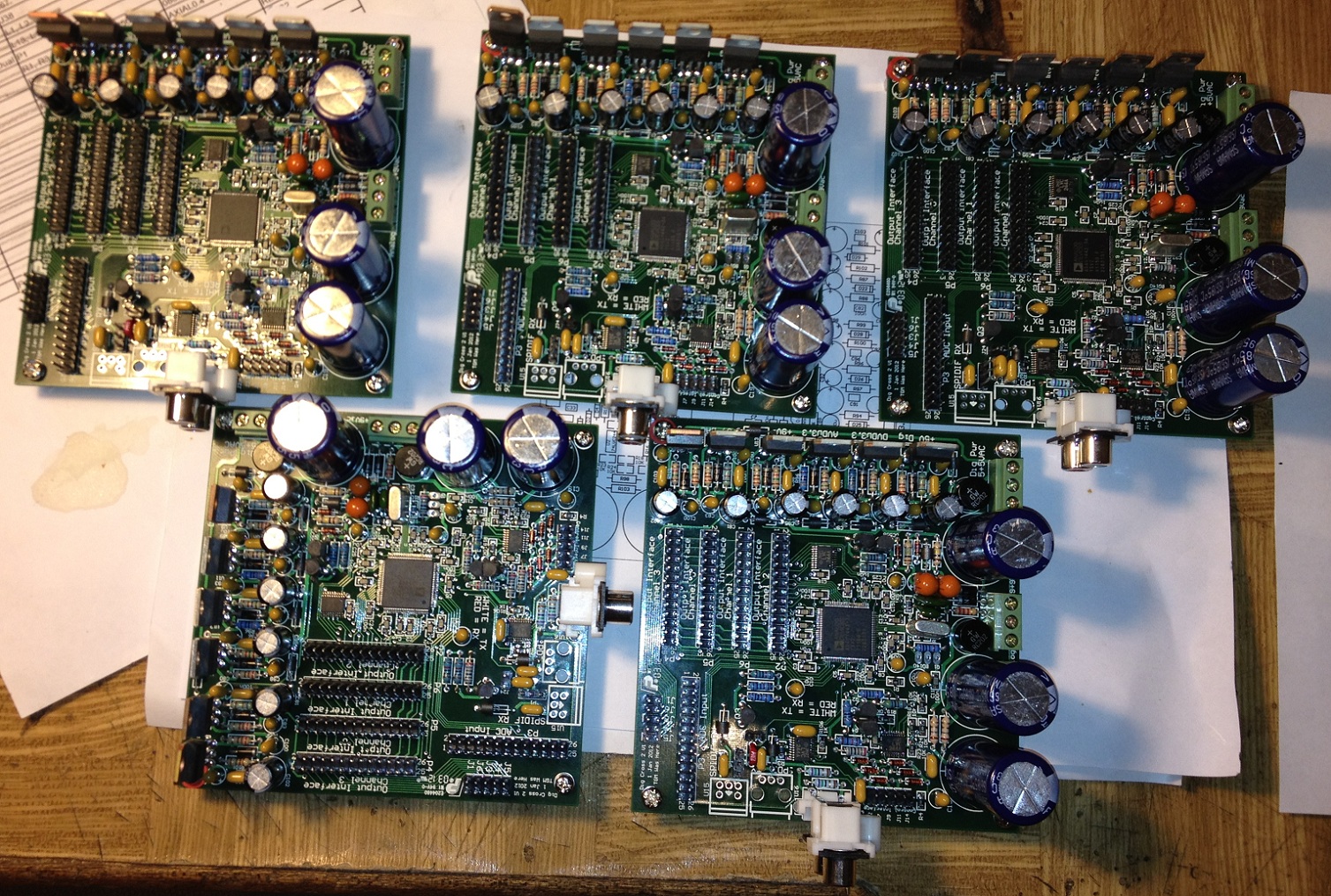
One thing that always used to give me grief at home was loading fine pitch surface mount IC's.

I recently bought a toaster oven having read several people's experience using these to relow SMD's.

I lashed out and bought the el-expensivo fan forced model, as this was in one forum reported to give more even heat. After some playing around I concluded the oven would actually be really very good.

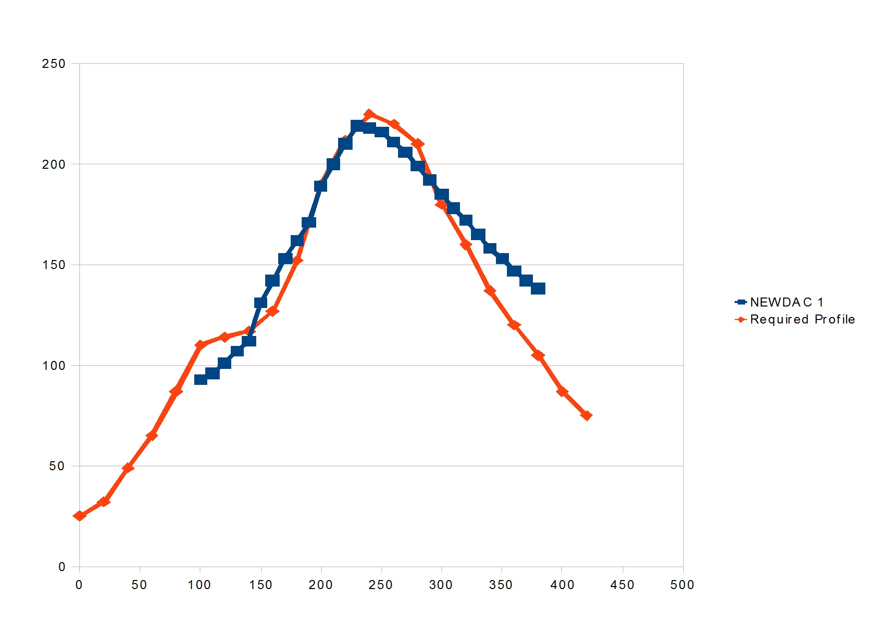
I found that if I did the following (with my oven):
- Turn on and run on 2 bars until temperature = 100C,
- Turn down to one bar, and run for 60 seconds,
- Turn on two bars and continue until the temperature is 210C,
- Turn all bars off, leave fan on and open the door a crack.

The heat continues to increase to about 220, and the profile is really very close to many manufacturers recommended profiles.

Click image for larger version

Name:	temp_Profile.jpg
Views:	445
Size:	127.9 KB
ID:	726

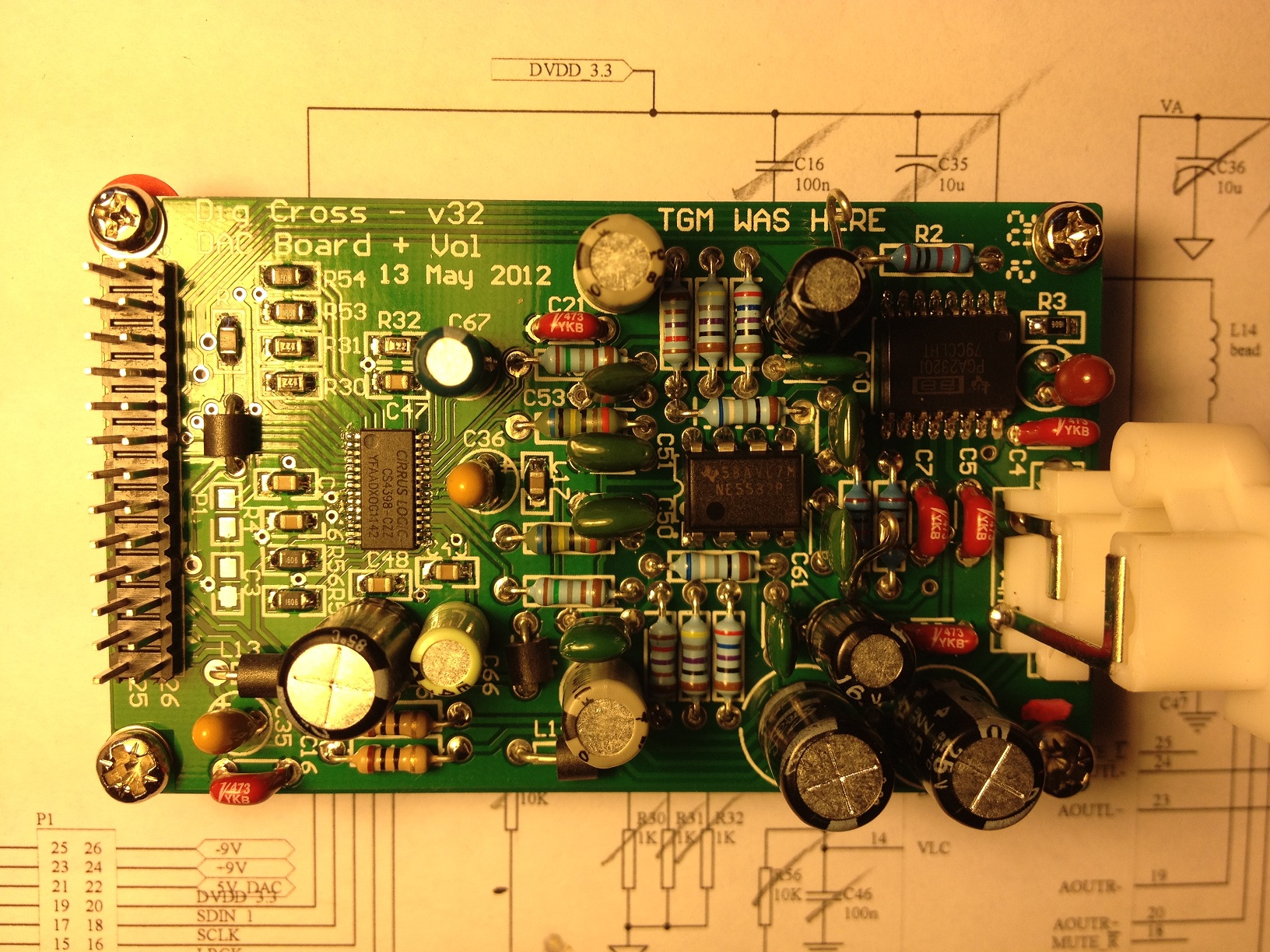
I don't use silksceeens, I use a syringe and put a very little...
Attached Thumbnails
Click image for larger version

Name:	DSC03829_small.jpg
Views:	947
Size:	723.6 KB
ID:	725  
diyAudio Member
Posted in Uncategorized
Views 3603 Comments 0 googlyone is offline
Old

OPTIMUS STA-2160

Posted 29th June 2012 at 07:27 PM by Antoinel

Hello
Does anyone have the schematic of the power amp section of the subject AM/FM receiver? Please share it. Thank you
diyAudio Member
Posted in Uncategorized
Views 1778 Comments 1 Antoinel is offline
Old

Mathematics of DAC droop correction

Posted 29th June 2012 at 05:09 AM by abraxalito

Here's one of the clearest articles I've seen which explains the background and a couple of solutions to DAC roll-off.

Flatten DAC frequency response | EDN

Both the solutions proposed compromise the dynamic range. My own solution, a hybrid analog/digital approach relies on DACs being cheap - I've termed it 'LAID' which stands for 'Longitudinal Array of Inexpensive DACs'.
abraxalito's Avatar
diyAudio Member
Views 1114 Comments 0 abraxalito is offline
Old

Front Panel Express Panels for the O2 Headphone Amp

Posted 28th June 2012 at 04:49 PM by MrSlim

The B2 file is for the BOX Enclosures B2-080 case, that is used in the standard "transportable" O2

The B3 files are for front and rear panels on a BOX Enclosures B3-080 case, used in the "Baby" desktop configuration of the O2. This configuration includes mounting holes for a 1/4" headphone jack and volume control on the front, with all the rest of the jacks and buttons on the back, along with a pair of RCA jacks for input. The PC board in Baby Desktop is installed backwards.
Attached Files
File Type: zip B2.zip (945 Bytes, 199 views)
File Type: zip B3_front.zip (565 Bytes, 192 views)
File Type: zip B3_rear.zip (823 Bytes, 171 views)
diyAudio Member
Posted in Uncategorized
Views 1366 Comments 0 MrSlim is offline
Old

New CS4398 plus PGA2320 DAC board set to work

Posted 25th June 2012 at 01:57 AM by googlyone

Click image for larger version

Name:	IMG_0225 - newDAC - small.jpg
Views:	2149
Size:	755.8 KB
ID:	719Just finished set to work of the new DAC for the digitial crossover. This includes a PGA2320 programmable attenuator on the output of the CS4398 DAC.

This replaces the home made PCB thai I was using on the CS4398 output. I went the professionally made board mainly because PCBCART was able to deliver 16 of these to my house for $140, that includes tooling!!! The actual boards were like $3 or 4 each!

The quality of these baords is fine - though I must admit that I am not breaking any new ground in PCB technology here.

The board is only double sided - I thought about adding a seperate ground and power plance - but the routing density is so lot it would be crazy. The whole back side only has a handful of tracks on it - and is a ground plane in itself. The top side even has room for significant ground fill.

All the digital stuff is in between the connector and the DAC, with a few SPI lines up the left hand...
diyAudio Member
Posted in Uncategorized
Views 3361 Comments 1 googlyone is offline
Old

Prototype MOS DAC

Posted 23rd June 2012 at 08:22 AM by abraxalito

The prototype is listenable now, but a bit too much background noise/hum pickup to do serious listening. It needs an on-board post filter and amp, which I'm working on now. In the meantime, here's the pics - the DAC itself is built of 5 'dac-sleds' each with a stack of 4 chips. The 'sleds' are then arranged around the central tower holding the resistor ladder. A separate board handles the timing logic and 18 tap delay line.
Attached Thumbnails
Click image for larger version

Name:	P1010084.JPG
Views:	1042
Size:	712.4 KB
ID:	715   Click image for larger version

Name:	P1010081.JPG
Views:	2681
Size:	714.1 KB
ID:	716   Click image for larger version

Name:	P1010078.JPG
Views:	1126
Size:	694.0 KB
ID:	717  
Attached Files
abraxalito's Avatar
diyAudio Member
Views 2677 Comments 3 abraxalito is offline
Old

NwAvGuy odac 24/96 DAC review

Posted 23rd June 2012 at 07:02 AM by rjm (RJM Audio Blog)
Updated 2nd July 2012 at 04:52 PM by rjm

I cased up my odac board (NwAvGuy via jtktam) in a small aluminum project box.

The DAC is a simple two-chip affair, with a Tenor TE7022L controller fronting the ESS ES9023 DAC and integrated line driver. A couple of voltage regulators, the clock oscillator, and an eeprom chip round out the principle component list.

I compared it with my Onkyo SE-200PCI sound card. This 24/192 (115dB S/N A-weighted, 0.003% THD 0dB 1kHz) PCI card sells for about $15,000 yen and is based on the VIA Envy24HT and Wolfson WM8740.

I'm listening to 16bit 44.1kHz .wav (CD rips), though VLC [sample rate converter set to sinc, best quality, resampling quality 8]. Windows 8 release preview [default format 24/192 (onkyo), 24/96 (odac)]. Line out though Oyaide PA-02TR interconnects to the Sapphire headphone amp, and Sennheiser HD-600s.

**

So, I was planning on writing up a big 'ol review with my impressions, but, well... there's not really a...
Attached Thumbnails
Click image for larger version

Name:	IMGP3077 1280.jpg
Views:	2392
Size:	379.9 KB
ID:	712   Click image for larger version

Name:	IMGP3031 1280.jpg
Views:	3825
Size:	349.2 KB
ID:	713   Click image for larger version

Name:	se200pci-hyojun.jpg
Views:	6302
Size:	648.6 KB
ID:	720  
Attached Files
File Type: pdf ODAC-release.pdf (196.7 KB, 912 views)
File Type: zip Odac and Onkyo Comparison.zip (28.3 KB, 405 views)
rjm's Avatar
rjm
diyAudio Member
Views 22611 Comments 20 rjm is offline

New To Site? Need Help?
Copyright ©1999-2017 diyAudio