

And now for something completely different...
As a kid, which depending on my wives mood could be stated to be "right now" right through to "you have never been a kid", I once made the statement that "if it can't be done with a BC549 it is not worth doing".
this statement was made in jest at the time, and probably stolen from a similar a similar assertion about the NE555. (those of you who are < 30 years old probably haven't seen these used in real anger!)
Here I am travelling, and flying from Adelaide (Australia) to the USA. This is a long, boring flight. In a fit of boredom I set myself a challenge.
So what is the challenge? Something cool and completely different for once. Hmm. Make a power amplifier using BS549's. If you have seem my play room, amplifiers are made to scare speakers and annoy the neighbours. So this can't be a lightweight 100mW job. It must be something that actually works, and is able to make real noise.
OK, it is ridiculous, and of no practical worth at all. Indeed, I am positive that there are aspects of this which are a gross compromise from using the right devices... BUT it is an amplifier made entirely of BS549/559's.... Isn't that cool?
What, you don't get it? Oh, OK. Well, I don't care. I am bored to my back teeth. Oh, and I have about three million of these devices at home.
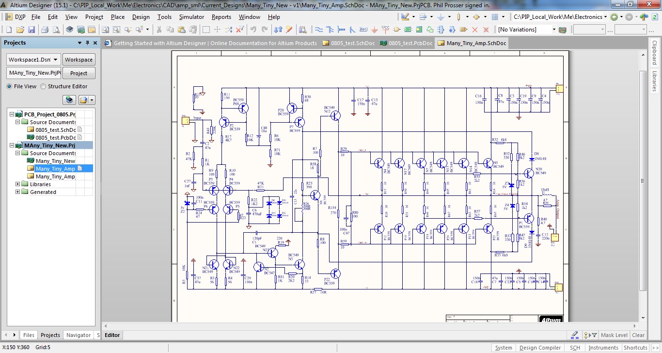
What am I talking about then? Well, this.
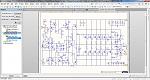
Which any member of this forum would recognise as being a blameless design. I am under no allusions that Douglas Self would spin in his metaphorical grave - notwithstanding the fact he is still amongst us - at the misapplication of his design goals in such a ludicrous application.
Refer above. This is for the fun. When I build it I will let you know how it measures! If it is rubbish, well then I will perhaps worry a bit. Will it be great? I rather doubt it! Will it work "OK" - I am sure it will.
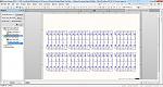
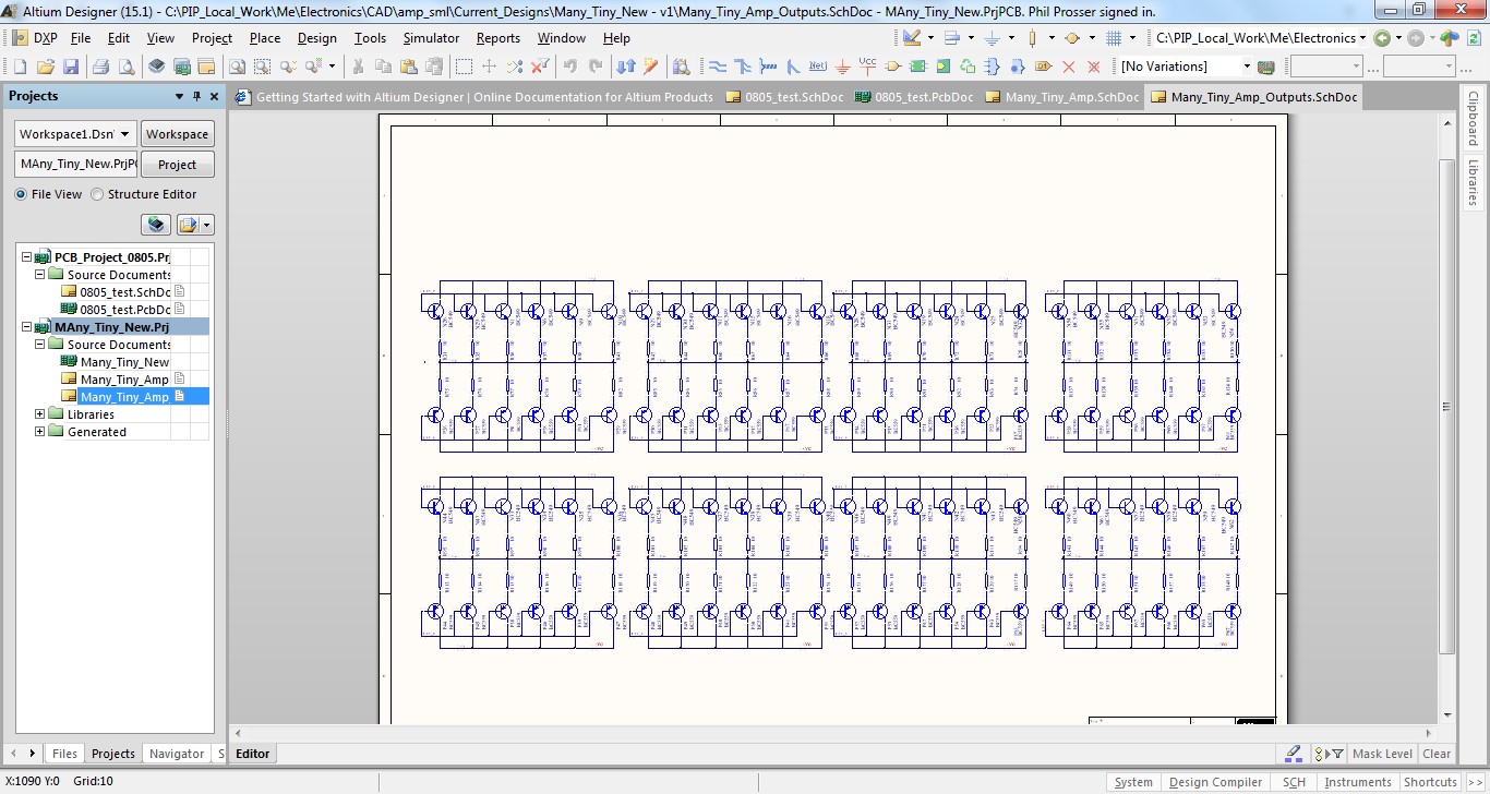
So - the thing has like 100 transistors in it... how the hell does it lay out? Ummm the front end is not awful, but fitting all those "output devices" on a board managed to while away several hours of sitting in an uncomfortable seat...
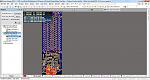
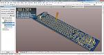
It all goes on a single sided PCB with a few wire links here and there.
What can it do?
- The rails will be +/-15V, maybe stretch to +/-17V. This is driven by the transistors SOA.
- Using 54 devices per side and +/-17V rails allows you to drive a 4 ohm speaker within the SOA of the "output devices". (isn't it cool to talk about a BC549 as an output device? Oh, ok you don't get it.)
- I thought of going to 100 devices per side. Just because I could, and also because I have so many of the stinking things at home. It would allow more output power, but cooling would become a serious issue if we crank up the voltage and current. Remember this thing will be relying on convection cooling - these "output devices" seem to be lacking mounting holes!
A few things to consider
- I am expecting there to be all manner of thermal gradients across the output devices. For this reason I have assumed there will be no less than 5-10 degrees Celsius difference between the hot and cold areas.
- This means that I need to expect up to 26mV difference in Vbe between devices (10 degrees...)
- Assuming that the bias current is in the region of 50mA, then there will be in the region of 1mA per device.
- I need to model this - but my gut says that by using about 10 Ohms emitter resistors, I will get adequate current sharing as temperatures change to keep things under control.
- The power tracks are LONG, and the "output devices" are frighteningly wide bandwidth. I might have designed a big RF oscillator disguised as "the amplifier of 100 transistors". Hmmm - need to build it to find out!
- It is still only 10-15 Watts....
- These "output devices" are NOT made for abuse. I have included a two slope SOAR protection circuit, that tracks quite close to the BC5XX device SOAR. This will play a role if you hit the amplifier with a 2 Ohm load or a short circuit. I doubt that a BC549 is as robust as an MJL21193!
Compromises are:
- The power supply routing to all the output devices is pretty rubbish. I am wondering if I can re-lay out the whole output stage, but in the end of the day, you have a huge area of transistors to handle.
- The power dissipation at +/-17V and driving a 4 Ohm speaker with a sinewave at about 10V pk looks to be in the region of 14 Watts across the "output devices". This is not insane, but will add up.
What will it do?
- Deliver probably something in the region of 15 watts into 4 Ohms.
- Probably perform OK, depending how much of a mess the power supply noise makes of the rest of the circuit.
- I expect the amplifier to either be easy to build, or very difficult to get stable! I suspect the high Ft of the output devices may give me some fun.
- It will make me smile.
- If I feel very, very bad I will do a CLASS A version. Just to be really silly.
I am going to make some boards in the next week or two, once I get home. If it works, this amplifier can sit atop the 1KW "Amplifier of Death" that is in my play room!
this statement was made in jest at the time, and probably stolen from a similar a similar assertion about the NE555. (those of you who are < 30 years old probably haven't seen these used in real anger!)
Here I am travelling, and flying from Adelaide (Australia) to the USA. This is a long, boring flight. In a fit of boredom I set myself a challenge.
So what is the challenge? Something cool and completely different for once. Hmm. Make a power amplifier using BS549's. If you have seem my play room, amplifiers are made to scare speakers and annoy the neighbours. So this can't be a lightweight 100mW job. It must be something that actually works, and is able to make real noise.
OK, it is ridiculous, and of no practical worth at all. Indeed, I am positive that there are aspects of this which are a gross compromise from using the right devices... BUT it is an amplifier made entirely of BS549/559's.... Isn't that cool?
What, you don't get it? Oh, OK. Well, I don't care. I am bored to my back teeth. Oh, and I have about three million of these devices at home.
What am I talking about then? Well, this.
Which any member of this forum would recognise as being a blameless design. I am under no allusions that Douglas Self would spin in his metaphorical grave - notwithstanding the fact he is still amongst us - at the misapplication of his design goals in such a ludicrous application.
Refer above. This is for the fun. When I build it I will let you know how it measures! If it is rubbish, well then I will perhaps worry a bit. Will it be great? I rather doubt it! Will it work "OK" - I am sure it will.
So - the thing has like 100 transistors in it... how the hell does it lay out? Ummm the front end is not awful, but fitting all those "output devices" on a board managed to while away several hours of sitting in an uncomfortable seat...


It all goes on a single sided PCB with a few wire links here and there.
What can it do?
- The rails will be +/-15V, maybe stretch to +/-17V. This is driven by the transistors SOA.
- Using 54 devices per side and +/-17V rails allows you to drive a 4 ohm speaker within the SOA of the "output devices". (isn't it cool to talk about a BC549 as an output device? Oh, ok you don't get it.)
- I thought of going to 100 devices per side. Just because I could, and also because I have so many of the stinking things at home. It would allow more output power, but cooling would become a serious issue if we crank up the voltage and current. Remember this thing will be relying on convection cooling - these "output devices" seem to be lacking mounting holes!
A few things to consider
- I am expecting there to be all manner of thermal gradients across the output devices. For this reason I have assumed there will be no less than 5-10 degrees Celsius difference between the hot and cold areas.
- This means that I need to expect up to 26mV difference in Vbe between devices (10 degrees...)
- Assuming that the bias current is in the region of 50mA, then there will be in the region of 1mA per device.
- I need to model this - but my gut says that by using about 10 Ohms emitter resistors, I will get adequate current sharing as temperatures change to keep things under control.
- The power tracks are LONG, and the "output devices" are frighteningly wide bandwidth. I might have designed a big RF oscillator disguised as "the amplifier of 100 transistors". Hmmm - need to build it to find out!
- It is still only 10-15 Watts....
- These "output devices" are NOT made for abuse. I have included a two slope SOAR protection circuit, that tracks quite close to the BC5XX device SOAR. This will play a role if you hit the amplifier with a 2 Ohm load or a short circuit. I doubt that a BC549 is as robust as an MJL21193!
Compromises are:
- The power supply routing to all the output devices is pretty rubbish. I am wondering if I can re-lay out the whole output stage, but in the end of the day, you have a huge area of transistors to handle.
- The power dissipation at +/-17V and driving a 4 Ohm speaker with a sinewave at about 10V pk looks to be in the region of 14 Watts across the "output devices". This is not insane, but will add up.
What will it do?
- Deliver probably something in the region of 15 watts into 4 Ohms.
- Probably perform OK, depending how much of a mess the power supply noise makes of the rest of the circuit.
- I expect the amplifier to either be easy to build, or very difficult to get stable! I suspect the high Ft of the output devices may give me some fun.
- It will make me smile.
- If I feel very, very bad I will do a CLASS A version. Just to be really silly.
I am going to make some boards in the next week or two, once I get home. If it works, this amplifier can sit atop the 1KW "Amplifier of Death" that is in my play room!
Total Comments 4
Comments
-

 Getting small signal transistors to play well together when maralleled I gave up on. But then I was using them in a classA design, you may have more luck in classAB. I think Doug Self found the same - parasitic oscillations are a devil to overcome.Posted 14th May 2016 at 04:57 AM by abraxalito

-
abraxalito, yes, this is no doubt a likely area of misery in this Ill-considered undertaking. But then, it wouldn't be fun if it just worked.
If you hear lots of cursing and shouting coming from down under it will be a fair bet that this has got the better of me!Posted 14th May 2016 at 10:46 PM by googlyone
-
If you get it working I shall be very interested as SOT-23 transistors are really so cheap - I shall be inclined to try a higher powered headphone amplifier with multiple output devices for a start. In the meantime though I'll play safe and use SOT-223s.Posted 18th May 2016 at 10:45 PM by abraxalito
-
I just finished a new layout which includes base resistors on each of the output devices. I am not sure whether these will be essential to achieving stability, but I figured that if I included (all 104) of these resistors in the layout, I can load them. If they prove unnecessary, then I guess I could put zero ohm links in - but I honestly think that is a fond hope.
Yep, I have a few reels of both NPN and PNP small signal transistors (mostly 549/550/559/560) which will without a doubt still be mostly full when depart this world.
For a headphone amp, a small handful of these would do. Their power dissipation is somewhat less than the TO92, which would be a limitation in this - admittedly ludicrous - application.
I will make a test board this weekend. The front end works fine, so the testing will be all about the output stage.
My plan is to start with a single pair of output devices, get the ting running and work from there watching to see what happens with stability in particular as the output devices and current scales up.Posted 20th May 2016 at 09:35 AM by googlyone

