

DIY Audio Analyser using CS4398 / CS5381
Posted 21st August 2015 at 05:16 AM by googlyone
Over the years I have played with measuring - well - just about everything in audio.
distortion measurement has been one of these preoccupations, not the least because it is hard to do, and using commercial gear, expensive.
I have built analogue hear to do this, used mixes of analogue and digital and of late played with using modified commercial sound cards. My efforts on the Sound Blaster x-Fi were interesting but ultimately not rewarding enough for me to leave the mods in there.
I have also been playing with using the A/D and D/A converters from my DSP crossover for this purpose. These are modular and use a common I/O plug with power MLCK, SCLK, LRCLK and Data (alone with I2S for the CS4398 and sometimes a digital volume control).
--- notwithstanding the fact that in previous tests I have shown the digital volume control is the MAJOR source of distortion - I will plug ahead with this, and likely leave that out of the test system.
A recent thread / discussion with JENS here:
https://www.diyaudio.com/forums/equip...ak4490-12.html
kicked me into a higher gear on this. The interesting thing was the ability to get data in and out of my PC without using a Sample Rate Converter. Tests I have done showed that the spectral impact of this was both obvious and unacceptable for a decent measurement system.
An additional issue I found was that many clock sources used in USB interfaces are absolutely awful, with jitter all over the place. When I built my oscillator, I intentionally used an odd clock rate for the DACS, as this allowed me to use no jittering / odd timing on the clocks. The effect on the spectral output of the sinewave was unbelievable. (Refer earlier blog).
A last thing that was essential was to galvanically isolate the thing from my computer. Connecting grounds in the test setup almost always ended in a "grasslike smear" of spurs.
These three things rolled into the design, which is an expension of the simple PIC microcontroller interface I built for my ADC / DACs.
Where am I at?
- I have built up an interface card that allows me to use a local clock;
- Provides power
- Provides galvanic isolation from the PC
- Interfaces to the minidsp streamer. I did talk to Jens about his work in this area, which confirmed a bunch of my design decisions. He does some clever stuff in extracting the sample rate from the Minidsp device - I decided not to include this, as this is a very dedicated piece of kit for me - and will be set to one sample rate. (Talk to him if you are interested in this.)
I was going to send this out to a fab - but I had a spare day and wanted to get my hands dirty. So I made the double sided PCB in my shed.
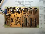
It is not perfect, and I had to put wire links in for all the vias took an hour or so, but I find this sort of thing therapeutic.
The interface is all set to work now, so tonight it is time to give the minidsp streamer a whirl!
I will be really interested to see what performance I can extract from the CS devices. (note that the analogue interfaces to the CS4398 / CS5381 are pretty much "off the shelf" CS circuits.)
distortion measurement has been one of these preoccupations, not the least because it is hard to do, and using commercial gear, expensive.
I have built analogue hear to do this, used mixes of analogue and digital and of late played with using modified commercial sound cards. My efforts on the Sound Blaster x-Fi were interesting but ultimately not rewarding enough for me to leave the mods in there.
I have also been playing with using the A/D and D/A converters from my DSP crossover for this purpose. These are modular and use a common I/O plug with power MLCK, SCLK, LRCLK and Data (alone with I2S for the CS4398 and sometimes a digital volume control).
--- notwithstanding the fact that in previous tests I have shown the digital volume control is the MAJOR source of distortion - I will plug ahead with this, and likely leave that out of the test system.
A recent thread / discussion with JENS here:
https://www.diyaudio.com/forums/equip...ak4490-12.html
kicked me into a higher gear on this. The interesting thing was the ability to get data in and out of my PC without using a Sample Rate Converter. Tests I have done showed that the spectral impact of this was both obvious and unacceptable for a decent measurement system.
An additional issue I found was that many clock sources used in USB interfaces are absolutely awful, with jitter all over the place. When I built my oscillator, I intentionally used an odd clock rate for the DACS, as this allowed me to use no jittering / odd timing on the clocks. The effect on the spectral output of the sinewave was unbelievable. (Refer earlier blog).
A last thing that was essential was to galvanically isolate the thing from my computer. Connecting grounds in the test setup almost always ended in a "grasslike smear" of spurs.
These three things rolled into the design, which is an expension of the simple PIC microcontroller interface I built for my ADC / DACs.
Where am I at?
- I have built up an interface card that allows me to use a local clock;
- Provides power
- Provides galvanic isolation from the PC
- Interfaces to the minidsp streamer. I did talk to Jens about his work in this area, which confirmed a bunch of my design decisions. He does some clever stuff in extracting the sample rate from the Minidsp device - I decided not to include this, as this is a very dedicated piece of kit for me - and will be set to one sample rate. (Talk to him if you are interested in this.)
I was going to send this out to a fab - but I had a spare day and wanted to get my hands dirty. So I made the double sided PCB in my shed.
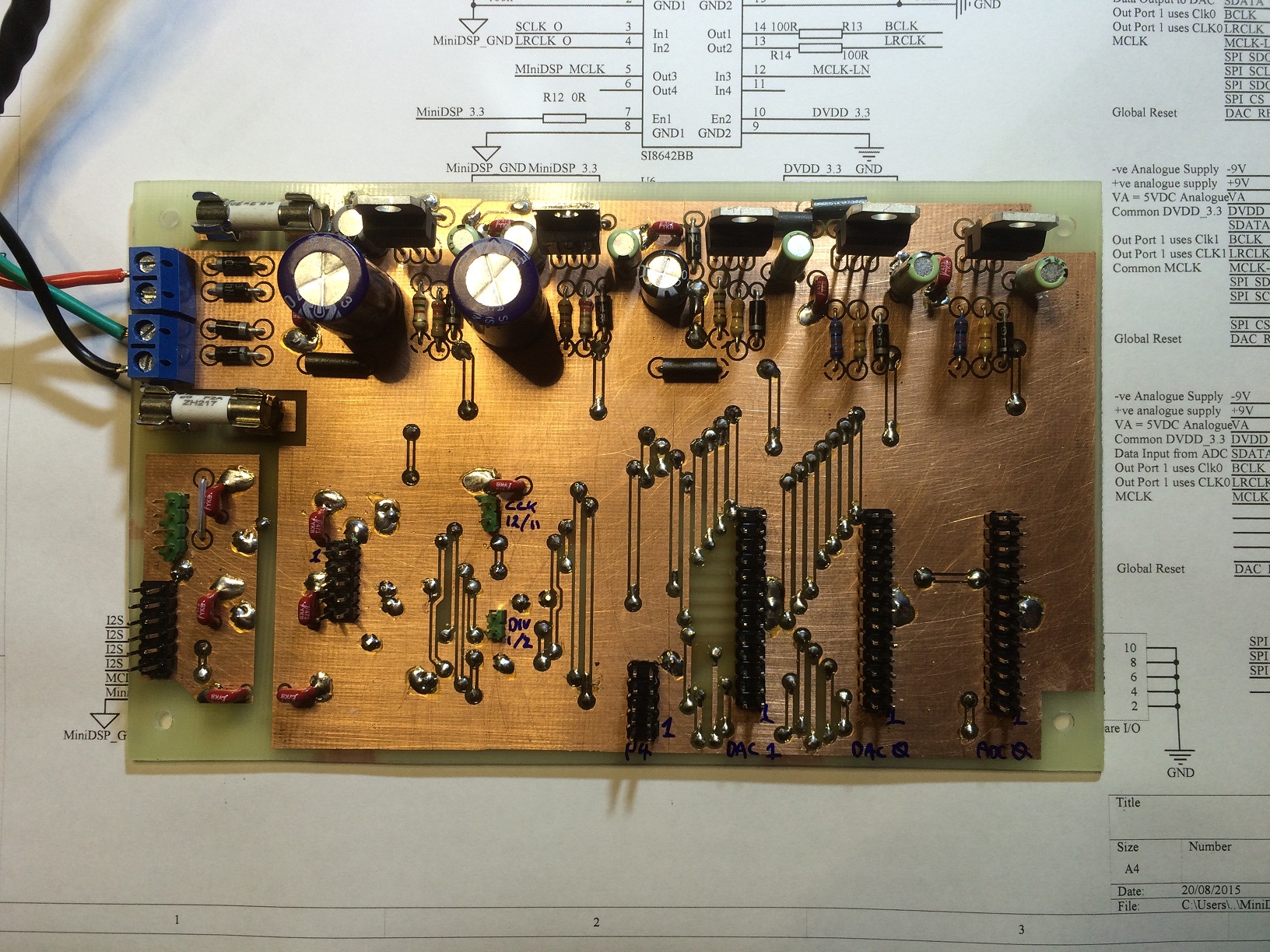
It is not perfect, and I had to put wire links in for all the vias
took an hour or so, but I find this sort of thing therapeutic.The interface is all set to work now, so tonight it is time to give the minidsp streamer a whirl!
I will be really interested to see what performance I can extract from the CS devices. (note that the analogue interfaces to the CS4398 / CS5381 are pretty much "off the shelf" CS circuits.)
Total Comments 0


