

Improving A/D perfromance of Sound Balster X-fi Music (SB1240) - and a Puzzle!!!
I have been playing with measuring distortion of signal sources and amplifiers a bit over the last year or two.
I am serious enough to spend some time and thought on this, but not serious enough to sink significant cash into application specific test equipment.
I have a couple of USB Sound Blaster X-fi Music (SB1240) sound cards I use for measurements. The original intent of these was for speaker test and general music. I am pressing these into use for more serious measurement.
The ADC in these is the Cirrus Logic CS5361, which is a pretty good ADC. The DAC is the AKM4396, which is a decent DAC.
When making measurements I hit a problem. The raw performance of the CS5361 is specced to be -99dBc guaranteed an -105dBc typical for THD+N. I couldn't get this.
A few things quickly went onto my list of things to try:
-1- Switching - the sound card has a lot of this - how was it implemented?
-2- Op amps - how good were they?
-3- The CS5361 has a "big brother" that is pic compatible, the CS5381.
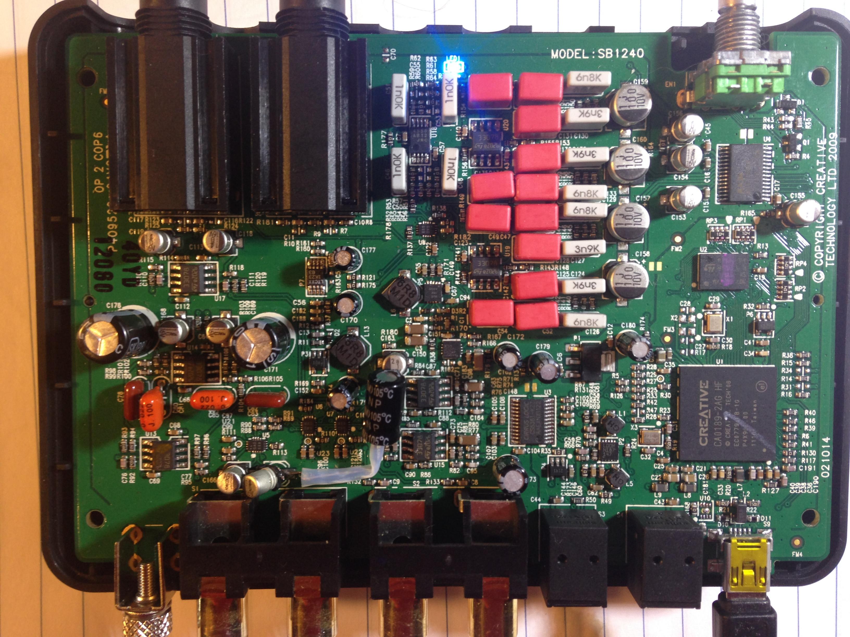
Firstly, what is inside the box?

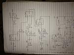
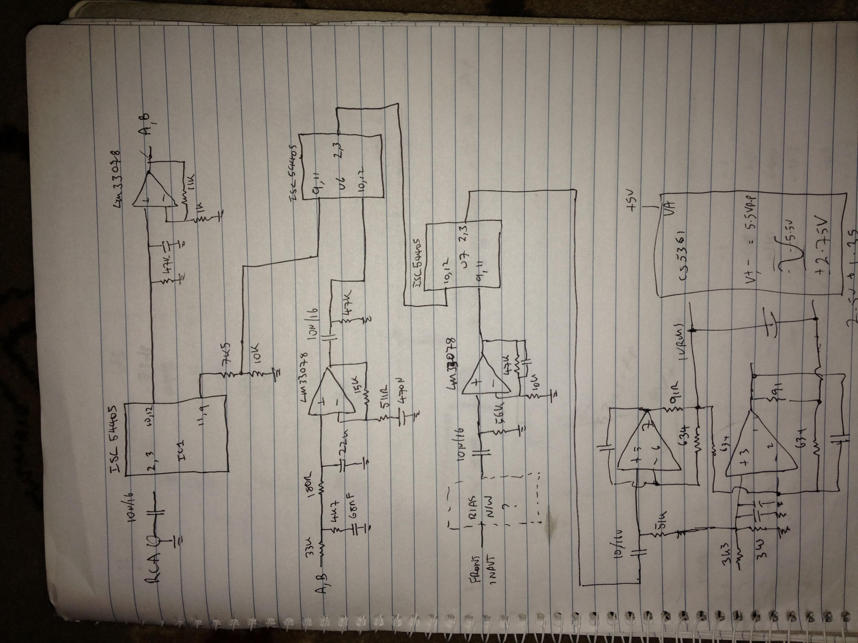
A bit of reverse engineering led to the following schematic of the input circuitry. Note I have only bothered with the input part, and stopped at the ADC.
The power supply is dealt with by some SMD boost converters. There appears to be an internal plane with power distribution, as I could see vias on power pins, but no traces. This made it - well lets say close enough - to impossible for me to get a good handle on what is going on with the power rails. This became pertinent later on...
The tiny little 16 pin SMD parts marked "GAD" were a puzzle, as there is not a great lot of reference to parts with this smt marking out there. After some research I stumbled on the Intersil ISL54405 data sheet. Yay! Finally I had it.
These are 2P2T analogue switches, which on the surface look to be some of the better analogue switches I have seen. They are definitely good enough for normal audio use, but the specs show that with elevated input voltages distortion can go higher than you would want. Key specs
- 2P2T
- 3.3-5V operation
- -106dB THD+N at 2VRMS, 20KOhm load
- 16 lead TSSOP, and in this case micro TQFN (read tiny)
What is the problem then, this is not bad...
There are three of these damn things in series when using the line in!
The line in has an attenuator on the output of the first switch, which means that the switch sees 5.4Volts p-p to achieve full scale on the ADC. OK, this is 2VRMS, which should not be too awful, but right from the offset we are introducing distortion.
Furthermore, the -106dB THD+N is typical. THe spec sheet does not provide guaranteed performance.
Then there is the use of the MC33078 opamp. Again this is a decent enough part, but you can do better.
The first mod I made was to jumper from the RCA input straight into the buffer opamp for the ADC.
Tests at 1KHz showed the following:
Unmodded Jumper input to buffer
Fundamental -1dB -1dB
2nd H -100dB -110dB
3rd H -97dB -104dB
4th H -122dB <-130
5th H -111dB -111dB
6th H <-130 <-130
Well worth doing. This in itself makes modding this worth the effort for me. That third third harmonic going from -97 to -104 is a big dela for this unit.
There are a couple of issues with this mod:
- You lose the ability to switch to the front panel, and also lose the ability to use the phono stage in th box. I have never used either, so I am a bit cavalier about such a vicious mod.
There may also be issues if you severely overdrive the input. The old approach used a voltage divider comprising a 7K5 and 10K resistor. Awful in terms of noise floor and maintaining a low input impedance to the op amp, but it does have the benefit of limiting current if you overdrive things.
With this mod, the opamp input is fed directly, so you have a good chance of toasting the ADC buffer amplifiers if you get silly. You might be able to put a 1K resistor in series and achieve a good level of protection without compromising noise and distortion too much.
As a test I did only one channel...

As can be seen, the easy way to achieve this is to pop the input caps, just next to the RCA connector, off the PCB, and also take the capacitors at the input to the ADC buffers, which are just next to the output RCA connectors. I used a bipolar capacitor to achieve this.
Next was to exchange the MC33078 op amp for a LM4562 op amp in one channel. I kind of had high hopes for this.
Getting these devices off is a bit tedious, but not killer. By using an LM4562 in the same package things go straight in...
The perfromance?
H3 goes down to -110dB, but..
H5 comes up from -111 to -109. Bugger!
OK, so the harmonics are now closer to -110dB than -104, not bad at all.
Hmmm. Lets buy some CS5381's and throw them in to see how things go. This is a pretty tedious thing to do as the CS5361CZZ is a very small lead pitch component, so desoldering this without proper kit is hard work.
Fast forward half an hour and a handful of curses... Them measure things... (note have left off the LM4562 numbers)
Unmodded I/P to buffer CS5381
Fundamental -1dB -1dB -1dB
2nd H -100dB -110dB -105dB
3rd H -97dB -104dB -90dB
4th H -122dB <-130 -117dB
5th H -111dB -111dB -125dB
6th H <-130 <-130 -117dB
Much more cursing. Why?
- I checked the reference bypass - I thotught I may have damaged the track, but no. Note that the CS5381 needs a larger cap on the reference bypass. Tried this, but it was not the issue.
- I checked the supply bypassing, no.
- I noted the VL and VD lines in this application are tied together. Possibly not ideal, but i works just fine with the CS5361... I added extra bypassing just to be sure.
- The CS5381 draws a fair bit more current than the CS5361. I increased the local bypassing of the ADC on the VA line. No prize.
I couldn't work out exactly what the limitations on the +5V regulator are - I would be surprised to see this killing things though. I do need to check this.
In the end I swapped the CS5381 for another one. The reasoning that drove me to this was that the ADC was working, and complaining about -90dBc on H3 is fair in 2015, but nevertheless this is still pretty fair performance. I convinced myself that maybe this particular device was out of spec.
No it was not. another half hour of me cursing and soldering away had another $20 IC on the board and that pesky -90dBc spur right back where it was half an hour before!!!!
Why?
Interestingly I still had one LM4562 on one channel and one MC33078 on the other. Both channels were exhibiting exactly the same problem.
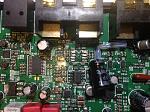
The ground plane under the ADC looks like this...
This is what I would do if I had a bunch of digital stuff right there on the same PCB. Hmmm
OK, did I mess something else up?
Another half hour of swearing, and I had swapped the $20 CS5381 for the original CS5361. I was kind of hoping to see the distortion still high, then I could find what I had broken and get back on track.
No such luck! The distortion plumeted back to the -110dBc territory!!!
So I am stumped. I need time to think this over, but without decent schematics and PCB layouts an reluctant to keep hacking into this card.
I have a bunch of ADCs that I use for my crossovers. Some of these have CS5361 and others CS5381's. I think I need to play with these and see what is causing this distortion.
Some obvious questions:
How do I know the distortion is not really there?
- I have characterised the DDS, and know that there is not a spur at -90dBc, done this by nulling the fundamental and measuring the harmonics.
One guess is that the input impedance of the CS5381 probably has something to do with what I am seeing.
A second guess is that the CS5381 is being driven with SCLK / LRCLK ratio of 32 (OK for CS5361, but out of spec for CS5381) - I will need to go check this....
If you have any experience in transitioning a CS5361 to CS5381 design and can shed some light on this, please let me know!!!!
Nevertheless, if you have a Sound Blaster X-Fi (SB1240) and want an extra 10dB odd on distortion spurs, then there are some serious gains to be had!!!
*******
NOTE:
*******
I now know that the drive circuit needs to be changed to have proper differential drive, as the current arrangement is not quite balanced. Additionally the capacitor across the CS5381 input probably needs to be larger than it is. With these mods, I would expect the sound balster to be more than 20dB better on most distortion measurements from 0 to -10dBc, and probably 10dB better across the range.
I am serious enough to spend some time and thought on this, but not serious enough to sink significant cash into application specific test equipment.
I have a couple of USB Sound Blaster X-fi Music (SB1240) sound cards I use for measurements. The original intent of these was for speaker test and general music. I am pressing these into use for more serious measurement.
The ADC in these is the Cirrus Logic CS5361, which is a pretty good ADC. The DAC is the AKM4396, which is a decent DAC.
When making measurements I hit a problem. The raw performance of the CS5361 is specced to be -99dBc guaranteed an -105dBc typical for THD+N. I couldn't get this.
A few things quickly went onto my list of things to try:
-1- Switching - the sound card has a lot of this - how was it implemented?
-2- Op amps - how good were they?
-3- The CS5361 has a "big brother" that is pic compatible, the CS5381.
Firstly, what is inside the box?
A bit of reverse engineering led to the following schematic of the input circuitry. Note I have only bothered with the input part, and stopped at the ADC.
The power supply is dealt with by some SMD boost converters. There appears to be an internal plane with power distribution, as I could see vias on power pins, but no traces. This made it - well lets say close enough - to impossible for me to get a good handle on what is going on with the power rails. This became pertinent later on...
The tiny little 16 pin SMD parts marked "GAD" were a puzzle, as there is not a great lot of reference to parts with this smt marking out there. After some research I stumbled on the Intersil ISL54405 data sheet. Yay! Finally I had it.
These are 2P2T analogue switches, which on the surface look to be some of the better analogue switches I have seen. They are definitely good enough for normal audio use, but the specs show that with elevated input voltages distortion can go higher than you would want. Key specs
- 2P2T
- 3.3-5V operation
- -106dB THD+N at 2VRMS, 20KOhm load
- 16 lead TSSOP, and in this case micro TQFN (read tiny)
What is the problem then, this is not bad...
There are three of these damn things in series when using the line in!
The line in has an attenuator on the output of the first switch, which means that the switch sees 5.4Volts p-p to achieve full scale on the ADC. OK, this is 2VRMS, which should not be too awful, but right from the offset we are introducing distortion.
Furthermore, the -106dB THD+N is typical. THe spec sheet does not provide guaranteed performance.
Then there is the use of the MC33078 opamp. Again this is a decent enough part, but you can do better.
The first mod I made was to jumper from the RCA input straight into the buffer opamp for the ADC.
Tests at 1KHz showed the following:
Unmodded Jumper input to buffer
Fundamental -1dB -1dB
2nd H -100dB -110dB
3rd H -97dB -104dB
4th H -122dB <-130
5th H -111dB -111dB
6th H <-130 <-130
Well worth doing. This in itself makes modding this worth the effort for me. That third third harmonic going from -97 to -104 is a big dela for this unit.
There are a couple of issues with this mod:
- You lose the ability to switch to the front panel, and also lose the ability to use the phono stage in th box. I have never used either, so I am a bit cavalier about such a vicious mod.
There may also be issues if you severely overdrive the input. The old approach used a voltage divider comprising a 7K5 and 10K resistor. Awful in terms of noise floor and maintaining a low input impedance to the op amp, but it does have the benefit of limiting current if you overdrive things.
With this mod, the opamp input is fed directly, so you have a good chance of toasting the ADC buffer amplifiers if you get silly. You might be able to put a 1K resistor in series and achieve a good level of protection without compromising noise and distortion too much.
As a test I did only one channel...
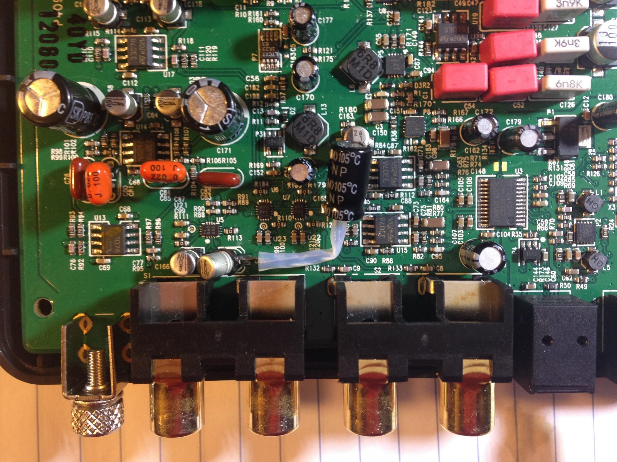
As can be seen, the easy way to achieve this is to pop the input caps, just next to the RCA connector, off the PCB, and also take the capacitors at the input to the ADC buffers, which are just next to the output RCA connectors. I used a bipolar capacitor to achieve this.
Next was to exchange the MC33078 op amp for a LM4562 op amp in one channel. I kind of had high hopes for this.

Getting these devices off is a bit tedious, but not killer. By using an LM4562 in the same package things go straight in...
The perfromance?
H3 goes down to -110dB, but..
H5 comes up from -111 to -109. Bugger!
OK, so the harmonics are now closer to -110dB than -104, not bad at all.
Hmmm. Lets buy some CS5381's and throw them in to see how things go. This is a pretty tedious thing to do as the CS5361CZZ is a very small lead pitch component, so desoldering this without proper kit is hard work.
Fast forward half an hour and a handful of curses... Them measure things... (note have left off the LM4562 numbers)
Unmodded I/P to buffer CS5381
Fundamental -1dB -1dB -1dB
2nd H -100dB -110dB -105dB
3rd H -97dB -104dB -90dB
4th H -122dB <-130 -117dB
5th H -111dB -111dB -125dB
6th H <-130 <-130 -117dB
Much more cursing. Why?
- I checked the reference bypass - I thotught I may have damaged the track, but no. Note that the CS5381 needs a larger cap on the reference bypass. Tried this, but it was not the issue.
- I checked the supply bypassing, no.
- I noted the VL and VD lines in this application are tied together. Possibly not ideal, but i works just fine with the CS5361... I added extra bypassing just to be sure.
- The CS5381 draws a fair bit more current than the CS5361. I increased the local bypassing of the ADC on the VA line. No prize.
I couldn't work out exactly what the limitations on the +5V regulator are - I would be surprised to see this killing things though. I do need to check this.
In the end I swapped the CS5381 for another one. The reasoning that drove me to this was that the ADC was working, and complaining about -90dBc on H3 is fair in 2015, but nevertheless this is still pretty fair performance. I convinced myself that maybe this particular device was out of spec.
No it was not. another half hour of me cursing and soldering away had another $20 IC on the board and that pesky -90dBc spur right back where it was half an hour before!!!!
Why?
Interestingly I still had one LM4562 on one channel and one MC33078 on the other. Both channels were exhibiting exactly the same problem.
The ground plane under the ADC looks like this...
This is what I would do if I had a bunch of digital stuff right there on the same PCB. Hmmm
OK, did I mess something else up?
Another half hour of swearing, and I had swapped the $20 CS5381 for the original CS5361. I was kind of hoping to see the distortion still high, then I could find what I had broken and get back on track.
No such luck! The distortion plumeted back to the -110dBc territory!!!
So I am stumped. I need time to think this over, but without decent schematics and PCB layouts an reluctant to keep hacking into this card.
I have a bunch of ADCs that I use for my crossovers. Some of these have CS5361 and others CS5381's. I think I need to play with these and see what is causing this distortion.
Some obvious questions:
How do I know the distortion is not really there?
- I have characterised the DDS, and know that there is not a spur at -90dBc, done this by nulling the fundamental and measuring the harmonics.
One guess is that the input impedance of the CS5381 probably has something to do with what I am seeing.
A second guess is that the CS5381 is being driven with SCLK / LRCLK ratio of 32 (OK for CS5361, but out of spec for CS5381) - I will need to go check this....
If you have any experience in transitioning a CS5361 to CS5381 design and can shed some light on this, please let me know!!!!
Nevertheless, if you have a Sound Blaster X-Fi (SB1240) and want an extra 10dB odd on distortion spurs, then there are some serious gains to be had!!!
*******
NOTE:
*******
I now know that the drive circuit needs to be changed to have proper differential drive, as the current arrangement is not quite balanced. Additionally the capacitor across the CS5381 input probably needs to be larger than it is. With these mods, I would expect the sound balster to be more than 20dB better on most distortion measurements from 0 to -10dBc, and probably 10dB better across the range.
Total Comments 2
Comments
-
 How does this unit compare to other phono adc units that you know of? Behringer has one, and so does ART. Are you familiar with these?
I'm interested in an ADC that will do the highest sampling rate possible. I'm open to a DIY, but I'm not an EE. I can solder and assemble, but electronic design isn't my thing.
Thanks!Posted 13th August 2015 at 05:54 PM by Harry Manback

-
The sound blaster is the only one that I have tested heavily.
From a normal audio / listening perspective it is not bad at all, though I have not tested the Phono stage.
Aspects that you might be concerned about:
- It does 24 bit
- it does 192KHz
- The THD+N is in the 0.00X % region, which in my mind makes it "good". Some people however want REALLY REALLY low distortion.
I guess I do too - but more for measurement than for listening. For listening I would not personally get overly fussed by the measured distortion of the SB.
I don't do "subjective" unless things just sound wrong - so I m the wrong person to ask if it "sounds better". to me the SB sounds just fine.Posted 21st August 2015 at 04:56 AM by googlyone

