

Flattening the NOS droop
Having been a fan of NOS DACs now for something over a year I've decided it was high time for sorting out their most serious drawback - the roll off in the HF. This is an unavoidable result of using a zero-order hold function to reconstruct the original (impulse) samples. Droop exists even with oversampled DACs, its just at its most severe in NOS.
One of the most popular ways to flatten the response is to add on some kind of analog filter with a rising response (to 3.16dB @ 20kHz). A first order shelving filter can't quite cut it though so an LC tank circuit has been employed by a few. This needs to have a moderately high Q to achieve the correction.
I've played around with inductors to achieve this and haven't much liked the resulting sound. Whether this was due to the particular inductors I was using I didn't experiment. Admittedly they were very cheap ones. In general though when I've used high Q circuits in crossovers I haven't much liked the colouration introduced. This I noticed happened when the Q was >0.7 in the audio band.
Now the resonant frequency of an LC tank to undo the droop is above the range of hearing - I found it needs to be close to 30kHz. So perhaps I wasn't hearing the direct result of the peakiness of at least 8dB which is necessarily introduced. But then again I might have been hearing 2nd order effects of raising the level of the imaging products beyond the audio band. Those are jolly undesirable because they are close in - to exacerbate them by 8dB or more seems unwise to me.
Another solution is to implement the correction filter in the digital domain. I've posted up such a filter on the 'Open source DSP XOs' thread. The problem with this approach is that I am using mere 16bit DACs in my designs. Any kind of digital filter produces a result which extends beyond 16bits and hence needs to be requantized to fit within 16bits once again. This means dither, which means added noise. Also there's a loss of dynamic range within the lower audio band to incorporate the 3.2dB of gain at 20kHz. Overall not a great option in my case because of the 16bit DAC bottleneck. I really wanted a solution with all the advantages of dynamic range which an analog filter gives, but without the messy high Q stuff.
Eventually after a lot of head scratching a solution came to me in a moment of clarity - a hybrid (analog-digital) FIR filter. Using DACs as analog-digital multipliers its possible to implement an FIR while doing the accumulation function in analog. The FIR coefficients are programmed in (as currents) to the reference input of the DACs (pin7 on the TDA1545) and each DAC is fed from a tapped delay line.
A quick bit of simulation with LTSpice using the delay lines showed that only a 3 tap filter was required if I was willing to compromise a bit on the flatness of the correction or the HF extreme. Seeing as I don't think I've got any hearing above 17kHz I decided to build a filter which corrected the droop only up to 17kHz and let the response above that fend for itself.
The 3 coefficients then turn out to be 1, -0.15, 0.026. Since my current DAC is 32 paralleled TDA1545s in a differential configuration, I needed to add 4 extra DACs each side for a total of 40. 3 of the extra DACs constitute the -0.15 coefficient (with a one-sample delay) and the final one gives the 0.026, delayed by two samples. More implementation details in a subsequent post - right now I'm going back to listening to the result which, incidentally I'm very pleased with
Total Comments 10
Comments
-
 Richard,
This seems very clever. Have you measured the frequency response @ 20kHz? I'm curious to know how much of a penalty there actually was at the band edge with the 3-tap filter.Posted 15th April 2012 at 12:22 AM by Ken Newton

-
 Thanks Ken - no, no measurements yet. Still too busy loving to listen to it to bother with a plot. But I will do one eventually.
Its jolly hard to get an accurate measurement of frequency response when there's aliasing nearby. In the end I used Audacity with FFT to estimate the amplitude (this with my inductor and shelving filters).. Still wasn't completely happy I got an accurate result though because there was a significant disagreement compared to the theory!Posted 15th April 2012 at 01:36 AM by abraxalito
-
 For 44.1kHz data, 20kHz audio waveform is being sampled at just 2 points per cycle. Perhaps it's better to make the reconstructed output at these frequencies less, rather than more audible.Posted 20th April 2012 at 11:35 PM by rjm
-
Actually, about 2.2 points per cycle. What's the problem with that?Posted 21st April 2012 at 12:52 AM by abraxalito
-
went ahead and tried what was posted on the tda1387 x8 thread
i never paused to think if it were applicable to my 4 stack implementation.
what are the factors that effects the values?Posted 30th November 2016 at 11:24 AM by nige2000
-
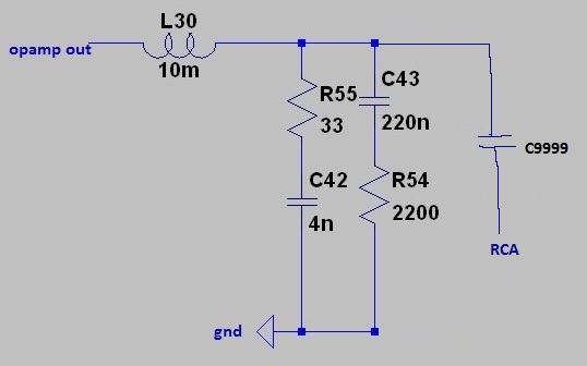
The input (where it says opamp out) is supposed to be driven by a low impedance. If you connect it to an I/V resistor it won't give the desired response because an I/V resistor isn't low enough impedance (>= 50ohm). Likewise the output (RCA) should not be loaded less than 22k.
L30./C42 define a resonant peak in the region 20-30k. R54 provides damping so that the peak isn't too sharp, we want something less than 5dB, C43 reduces the damping where its not required, at LF.Posted 30th November 2016 at 03:15 PM by abraxalito
-
so fixing the nos droop with this method isn't a runner with an i/v resistor?
is there a method of measuring impedance of a buffer or opamp?Posted 30th November 2016 at 04:02 PM by nige2000
-
You'd want a buffer first - Matt Garman sketched up a schematic of I/V followed by buffer and filter on the 8 * TDA1387 thread.
Output impedance can be measured yeah - you need a test source i.e. signal gen or for DAC, test waveform. You can create test waveforms in Audacity. Say you want to measure at 440Hz, create a sine at this frequency then with an AC voltmeter (should be sensitive, 4 digit DMM should work) measure the output voltage. Then put a load on say 1k, measure again. Math on those two voltages gives the output impedance.Posted 30th November 2016 at 11:39 PM by abraxalito
-
what if i had the bc807 for i/v and feed 3.3v from float charged lifepo4 cell into base?Posted 1st December 2016 at 12:12 AM by nige2000
-
The transistor is just a current conveyor in that situation - it reduces the ps sensitivity of the DAC but does nothing to reduce the output impedance. Hence still needs buffering.Posted 1st December 2016 at 12:37 AM by abraxalito

